EP1102475A1 - Procede de transmission d'images et dispositif pour sa mise en oeuvre - Google Patents
Procede de transmission d'images et dispositif pour sa mise en oeuvre Download PDFInfo
- Publication number
- EP1102475A1 EP1102475A1 EP99933187A EP99933187A EP1102475A1 EP 1102475 A1 EP1102475 A1 EP 1102475A1 EP 99933187 A EP99933187 A EP 99933187A EP 99933187 A EP99933187 A EP 99933187A EP 1102475 A1 EP1102475 A1 EP 1102475A1
- Authority
- EP
- European Patent Office
- Prior art keywords
- effective region
- minimum unit
- extent
- designation minimum
- effective
- Prior art date
- Legal status (The legal status is an assumption and is not a legal conclusion. Google has not performed a legal analysis and makes no representation as to the accuracy of the status listed.)
- Granted
Links
- 230000005540 biological transmission Effects 0.000 title claims description 64
- 238000000034 method Methods 0.000 title claims description 30
- 230000001360 synchronised effect Effects 0.000 claims description 6
- 230000004044 response Effects 0.000 claims 24
- 238000010586 diagram Methods 0.000 description 6
- 238000004891 communication Methods 0.000 description 2
Images


Classifications
-
- H—ELECTRICITY
- H04—ELECTRIC COMMUNICATION TECHNIQUE
- H04N—PICTORIAL COMMUNICATION, e.g. TELEVISION
- H04N1/00—Scanning, transmission or reproduction of documents or the like, e.g. facsimile transmission; Details thereof
- H04N1/387—Composing, repositioning or otherwise geometrically modifying originals
- H04N1/3872—Repositioning or masking
- H04N1/3873—Repositioning or masking defined only by a limited number of coordinate points or parameters, e.g. corners, centre; for trimming
Definitions
- the present invention relates to an image transmitting method for transmitting image data of a camera such as a digital camera and also to an image transmitting system for carrying out said method.
- the invention relates to an image transmitting method for transmitting an arbitrary image region on a picture of a camera, and to an image transmitting system for carrying out said method.
- Fig. 5 explains a method for designating an arbitrary image region (which may be all or a part of a picture) on a picture taken by a camera.
- Fig. 5A is a drawing to show a region on the picture and dimension, and Fig. 5B indicates parameters for designating the region.
- Extent (size) and position (expressed as A, B, C', D', E, F, G, and H) of each portion of the effective region given in the parameters of Fig. 5B represent extent (size) and position of portions shown by each of the corresponding symbols (A ⁇ H) in the image region shown in Fig. 5A. That is, a symbol "A” given in (1) of Fig. 5B denotes the maximum value of an extent of an effective region (an image region designated for transmission; the same applies hereinafter.) in horizontal direction. “B” represents the maximum value of an extent of an effective region in vertical direction. A symbol "C” given in (2) of Fig.
- FIG. 5B represents a designation minimum unit of an effective region in horizontal direction
- “D” represents a designation minimum unit of the effective region in vertical direction
- a symbol “E” given in (3) of Fig. 5B represents a position of an effective region in horizontal direction
- “F” represents a position of the effective region in vertical direction
- “G” given in (4) of Fig. 5B represents a size of the effective region in horizontal direction
- "H” represents a size of the effective region in vertical direction.
- the image transmission procedure is started, and the image data of the effective region designated above are transmitted over a network.
- the designation minimum unit (C', D') for designating the position (E, F) of the effective region for image transmission and the designation minimum unit (C', D') for designating the size (G, H) of the effective region the same designation minimum unit is used. Accordingly, in case there is a restriction on the setting of either one of the designation minimum unit of position of the effective region or the designation minimum unit of the extent of the effective region, the restriction on one of them is also applied or extended to the other, and free designing cannot be carried out.
- a designation minimum unit (I, J) for determining the position of the effective region is set independently and separately from a designation minimum unit (C, D) for determining the extent of an image region to be transmitted (hereinafter referred as "effective region").
- the designation minimum unit for determining the extent of the effective region and the designation minimum unit for determining the position of the effective region are set independently from each other.
- the designation minimum unit for designating the position of the effective region and the designation minimum unit for designating the size of the effective region it can be designed in such manner that the restriction on one of them is not extended or applied to the other.
- the image transmitting method comprises the steps of setting the maximum value of an extent of an effective region in horizontal direction and vertical direction, a designation minimum unit of an extent of the effective region in horizontal direction and vertical direction, and a designation minimum unit of a position of the effective region in horizontal direction and vertical direction, setting a position and a size of the effective region designated from an external operation/control unit, and inputting only an image data included in the effective region and outputting it to outside.
- the values of the designation minimum unit of the extent of the effective region in horizontal direction and vertical direction are set to values independent and separate from the values of the designation minimum unit of the position of the effective region in horizontal direction and vertical direction. Even when there is restriction on one of the designation minimum unit for designating the position of the effective region or the designation minimum unit for designating the size of the effective region, it can be designed in such manner that the restriction on one of them is not extended or applied to the other.
- the designation minimum unit of the position of the effective region is set to a value smaller than the designation minimum unit of the extent of the effective region. Because the designation minimum unit of the position of the effective region is set to a value smaller than the designation minimum unit of the extent of the effective region, and this makes it possible to set the shifting of the effective region in more elaborate manner.
- the image transmitting system of the present invention comprises image acquisition means for converting an image input obtained by photographing to a digital electric signal, transmission means for processing the digital electric signal received from the image acquisition means and for outputting pixel data of the effective region to be transmitted to an external device, and transmission control means for supplying an effective pixel value setting signal for setting to transmit pixel data based on a command from an external operation/control unit to the transmission means.
- the transmission control means is designed to hold the maximum value of the extent of the effective region, the designation minimum unit of the extent of the effective region, and the designation minimum unit of the position of effective region.
- the designation minimum unit for designating the position of the effective region is set separately from the designation minimum unit for designating the size of the effective region. As a result, the size of the effective region and the position of the effective region can be set without any restriction on each other.
- the designation minimum unit of the extent of the effective region is set to a value independent and separate from the designation minimum unit of the position of the effective region.
- the designation minimum unit for designating the size of the effective region is set separately from the designation minimum unit for designating the position of the effective region.
- the designation minimum unit of the position of the effective region is set to a value smaller than the designation minimum unit of the extent of the effective region.
- the designation minimum unit of the position of the effective region is set to a value smaller than the designation minimum unit of the extent of the effective region, and the shifting of the effective region can be set in more elaborate manner.
- Fig. 1 is used to explain a designation method for designating an arbitrary image region (all or a part) of a picture photographed by a camera for transmission purpose.
- Fig. 1A is a drawing to show an effective region on the picture and dimension, and Fig. 1B indicates parameters for designating the effective region.
- Each of the extent and the size (represented by A, B, C, D, E, F, G, H, I, and J) of each portion of the effective region with the parameters given in Fig. 1B represents extent and size of a portion given by each of the corresponding symbols (A ⁇ J) in the image region shown in Fig. 1A.
- a symbol "A” given in (1) of Fig. 1B indicates the maximum value of an extent of an effective region in horizontal direction
- “B” indicates the maximum value of an extent of an effective region in vertical direction.
- a symbol “C” given in (2) of Fig. 1B indicates a designation minimum unit of an extent of an effective region in horizontal direction
- "D” indicates a designation minimum unit of an extent of an effective region in vertical direction.
- a symbol “E” in (3) of Fig. 1B indicates a position of an effective region in horizontal direction
- “F” indicates a position of an effective region in vertical direction
- a symbol “G” given in (4) of Fig. 1B indicates a size of an effective region in horizontal direction
- “H” indicates a size of an effective region in vertical direction
- a symbol “I” given in (5) of Fig. 1B indicates a designation minimum unit of a position of an effective region in horizontal direction
- " J” indicates a designation minimum unit of a position of an effective region in vertical direction.
- the operation/ control unit determines a size (G: horizontal direction; H: vertical direction) of the effective region, which is an integral multiple of a designation minimum unit (C: horizontal direction; D: vertical direction) of the extent of the effective region and within the maximum value of the extent of the effective region.
- the control unit determines a position of the effective region (E: horizontal direction; F: vertical direction) regardless of the designation minimum units C and D of the extent of the effective region, and these data are set in a register of the camera.
- An extent of a region (effective region) to be transmitted is determined by the size (G: horizontal direction; H: vertical direction) of the above effective region, and the position of the effective region on the picture is determined by the designation minimum unit (I: horizontal direction; J: vertical direction) of the position of the effective region.
- the values of these parameters are set in the memory of transmission control means (to be described later), and an image transmitting procedure is started, and the effective region designated in the above, i.e. an image data in the effective region, is transmitted over a network.
- designation minimum unit for designating the position of the effective region
- designation minimum unit for designating the size of the effective region
- FIG. 2 is a block diagram schematically showing an entire image transmitting system in the embodiment of the present invention
- Fig. 3 is a detailed block diagram of transmission means shown in Fig. 2.
- Fig. 4 shows the details of the effective region judging means shown in Fig. 3.
- Fig. 4A is a block diagram of the effective region judging means
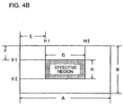
- Fig. 4B shows an effective region judged by the effective region judging means.
- reference numeral 101 denotes image acquisition means for converting an image taken by a camera and for outputting it
- 102 indicates transmission means for processing a digital electric signal received from the image acquisition means 101 and for outputting only pixel data of the effective region to an external device (e.g. personal computer, monitor, recording system, etc.) connected to a network which requests such data
- Reference numeral 103 is transmission control means for supplying a command from an external operation/control unit (shown as external control means in the figure) 104, i.e. an effective pixel value setting signal for setting an effective pixel to be transmitted to the transmission means 12 by an operation/control signal.
- an external operation/control unit shown as external control means in the figure
- the transmission control means 103 has a memory (not shown).
- the maximum value (A, B) of an extent of the effective region and the designation minimum unit (C, D) of the extent of the effective region are set.
- a position of the effective region (E, F) and a size (G, H) of the effective region are set according to a command from the external operation/control unit 104.
- the image acquisition means 101 acquires an image taken by the camera, for instance, and this is converted to an image data as a digital electric signal, and it is outputted to the transmitting means 102.
- the transmitting means 102 Based on the position of the effective region (E, F) and the size of the effective region (G, H) received from the transmission control means 103, the transmitting means 102 stores only the pixel data of the effective region in the memory at proper timing with the inputted image data.
- the memory which stores the data is outputted to outside as a packet.
- reference numeral 1 denotes a memory, which temporarily stores only the pixels in the effective region of an image data received from the image acquisition means 101
- 2 indicates processing means for temporarily storing each of the pixel data inputted to the memory 1 according the position of the effective region (E, F) and the size of the effective region (G, H) received from the transmission control means 103 at proper timing with a timing signal acquired from the image acquisition means 101.
- Reference numeral 3 is a bus I/F circuit for interfacing data and control signal between the external network and the operation/control unit 104 on one hand and the transmission control means 103 and the processing means 2 on the other hand.
- Reference numeral 5 comprises a position memory, and it is effective pixel value holding means for receiving an effective pixel value setting signal to indicate address of an effective pixel designating the effective region from the transmission control means 103 and for holding the effective pixel values (H1 and H2, and V1 and V2 shown in Fig. 4B).
- Reference numeral 4 is effective region judging means for outputting an effective signal "1" to the processing means 2 when the image data sent from the image acquisition means 101 is within the effective region (given by H1, H2, V1 and V2).
- a timing signal shown in Fig. 3 is given from the image acquisition means of Fig. 2 together with the image data.
- the timing signal includes a clock signal, a horizontal synchronizing signal and a vertical synchronizing signal, and these are synchronized with the image data, which serves as digital electric signal.
- the transmission control means 103 outputs the maximum value (A, B) of the extent of the effective region as set in the memory (not shown), size designation minimum unit (C: horizontal direction; D: vertical direction) to designate the extent of the effective region, and position designation minimum unit (I: horizontal direction; D: vertical direction) to designate the position of the effective region based on a command from the external operation/control unit 104.
- the transmission control means 103 receives a communication information, i.e.
- the size designation minimum unit C in horizontal direction can be set to 4 pixels, for instance, and the size designation minimum unit D in vertical direction can be set to 1 pixel (1 horizontal line), for instance.
- the position designation minimum unit I in horizontal direction can be set to 1 pixel, for instance, and the position designation minimum unit J in vertical direction can be set to 1 pixel (1 horizontal line), for instance.
- the transmission control means 103 Based on the position (E, F) of the effective area and the size (G, H) of the effective region thus acquired, the transmission control means 103 outputs an effective pixel value setting signal including horizontal pixel values (H1, H2) and vertical effective pixel values (V1, V2) for specifying the effective region on the picture.
- the horizontal effective pixel value indicates that it is effective between the positions H1 and H2, and the vertical effective pixel value indicates that it is effective between the positions V1 and V2.
- the effective pixel value holding means 5 holds the received effective pixel value and outputs it to the effective region judging means 4.
- the effective region judging means 4 counts each pixel on the picture according to the timing signal acquired from the image acquisition means 101 and outputs an effective signal "1" to the processing means when the position given by the count agrees with the position given by the received effective pixel values (H1, H2, V1, and V2). Because the processing means is synchronized by the same timing signal, the position where the effective signal "1" has been received can be identified. A control signal is sent immediately to the memory 1, and the pixel data corresponding to the effective signal "1" is stored in the memory 1.
- reference numeral 11 denotes a counter for receiving a clock signal and for counting pixels in horizontal direction (from 1 to n1) on the picture
- reference numeral 12 is a counter for counting horizontal lines in vertical direction (from 1 to n2) on the picture
- Reference numeral 13 is comparison means for comparing the count value of the counter 11 with the horizontal effective pixel values (H1, H2) from the effective pixel value holding means 5 and for outputting a horizontal effective signal "1" in case the count value is within the range from H1 to H2.
- the clock signal has number of pulses (frequencies) to match the number of pixels (rate) on the horizontal line.
- Reference numeral 14 denotes comparison means for comparing the count value of the counter 12 with the vertical effective pixel values (V1, V2) from the effective pixel value holding means 5 and for outputting a vertical effective signal "1" in case the count value is within the range from V1 to V2.
- Reference numeral 15 is logical product means for obtaining a logical product of output signals of the comparison means 13 and the comparison means 14 and for outputting an effective signal "1" in case both output signals are logic "1".
- an effective region in the maximum value (A: horizontal direction; B: vertical direction) of the extent of the effective region in the entire image region photographed, an effective region is designated, which has the position (E, F) of the effective region as a starting point (given by the horizontal effective pixel value H1 and the vertical effective pixel value V1) and which is defined by the horizontal effective pixel values (H1, H2) showing the position of the effective region in horizontal direction and by the vertical pixel values (V1, V2) showing the position of the effective region in vertical direction.
- the horizontal effective pixel values (H1, H2) are count values counting the pixels from the left end of the image region defined by the maximum values A and B of the extent of the effective region.
- the vertical effective pixel values (V1, V2) are count values counting the pixels from the upper end of the image region. Specifically, a left upper corner of the image region defined by the maximum values A and B of the extent of the effective region is used as a reference point, and number of pixels is counted. The reference point is not limited to the left upper corner, but it can be set at any point as desired. As described later, when the effective region is counted, the effective signal "1" is outputted from the effective region judging means 4.
- the counter 11 outputs a count value, which is counted at all times (counted up) by the clock signal contained in the timing signal and indicates address value of the pixels in horizontal direction.
- the counter 12 outputs a count values, which is counted by the horizontal synchronizing signal contained in the timing signal (photographed pixels are counted in vertical direction) and indicates address value of the pixels in vertical direction.
- the maximum value (B) in vertical direction of the extent of the effective region shown in Fig. 4B is reached, it is reset by the vertical synchronizing signal and returns to the initial value in vertical direction of the extent of the region.
- the comparison means 13 receives the horizontal effective pixel values (H1, H2) from the effective pixel value holding means 5, monitors and compares with the count value from the counter 11, and outputs a horizontal effective signal "1" in case the count value is within the range from H1 to H2. Further, the comparison means 14 receives the vertical effective pixel values (V1, V2) from the effective pixel value holding means 5, monitors and compares with the count value from the counter 12, and outputs a vertical effective signal "1” in case the count value is within the range from V1 to V2.
- the logical product means 15 receives the horizontal effective signal and the vertical effective signal and, in case both signals are "1", outputs an effective signal "1", showing that the count is within the effective region, to the processing means 2.
- the position designation minimum unit e.g. 1 pixel
- the size designation minimum unit e.g. 4 pixels
- the setting of the position can be performed in more elaborate manner.
- the size designation minimum unit is smaller than the position designation minimum unit, the setting of the size can be performed in more elaborate manner.
- a reference position of the effective region to a reference position of 2-dimensional image region at all times and to change only the extent of the effective region.
- a left upper corner in 2-dimensional image region is regarded as a reference point and the effective region is defined by horizontal and vertical distances from this point.
- the position designation minimum unit is a value independent from the position designation unit, the size designation can be performed according to the maximum value of the effective region and to the size designation minimum unit.
- the designation minimum unit for determining the extent of the effective region and the designation minimum unit for determining the position of the effective region are set independently from each other. As a result, even when there is a restriction on the setting of one of the designation minimum unit for designating the position of the effective region or the designation minimum unit for designating the size of the effective region, it is possible to set in such manner that the restriction on one of them is not extended or applied to the other.
- the designation minimum unit for determining the extent of the effective region and the designation minimum unit for determining the position of the effective region are set independently from each other.
- the designation minimum unit "I, J" for determining the position of the effective region is set to a value smaller than the designation minimum unit "C, D" for determining the extent of the effective region in order to more elaborately set the position of the effective region.
- the reference position of the effective region can be fixed and the effective region can be set simply depending on the extent of the effective region.
Landscapes
- Engineering & Computer Science (AREA)
- Multimedia (AREA)
- Signal Processing (AREA)
- Two-Way Televisions, Distribution Of Moving Picture Or The Like (AREA)
- Editing Of Facsimile Originals (AREA)
- Compression Or Coding Systems Of Tv Signals (AREA)
- Image Processing (AREA)
- Image Input (AREA)
- Facsimile Transmission Control (AREA)
- Studio Devices (AREA)
- Closed-Circuit Television Systems (AREA)
- Processing Or Creating Images (AREA)
Applications Claiming Priority (3)
| Application Number | Priority Date | Filing Date | Title |
|---|---|---|---|
| JP22951398 | 1998-07-31 | ||
| JP22951398A JP4098892B2 (ja) | 1998-07-31 | 1998-07-31 | 画像伝送装置、デジタルカメラ、画像処理装置、画像伝送方法、画像伝送方法、及び画像の有効領域指定方法 |
| PCT/JP1999/004111 WO2000007359A1 (fr) | 1998-07-31 | 1999-07-30 | Procede de transmission d'images et dispositif pour sa mise en oeuvre |
Publications (3)
| Publication Number | Publication Date |
|---|---|
| EP1102475A1 true EP1102475A1 (fr) | 2001-05-23 |
| EP1102475A4 EP1102475A4 (fr) | 2006-10-04 |
| EP1102475B1 EP1102475B1 (fr) | 2009-02-18 |
Family
ID=16893360
Family Applications (1)
| Application Number | Title | Priority Date | Filing Date |
|---|---|---|---|
| EP99933187A Expired - Lifetime EP1102475B1 (fr) | 1998-07-31 | 1999-07-30 | Procede de transmission d'images et dispositif pour sa mise en oeuvre |
Country Status (9)
| Country | Link |
|---|---|
| US (1) | US6798922B1 (fr) |
| EP (1) | EP1102475B1 (fr) |
| JP (1) | JP4098892B2 (fr) |
| CN (1) | CN1192594C (fr) |
| AU (1) | AU759459B2 (fr) |
| CA (1) | CA2339152C (fr) |
| DE (1) | DE69940432D1 (fr) |
| TW (1) | TW425814B (fr) |
| WO (1) | WO2000007359A1 (fr) |
Cited By (2)
| Publication number | Priority date | Publication date | Assignee | Title |
|---|---|---|---|---|
| EP1548643A1 (fr) * | 2002-10-04 | 2005-06-29 | Sony Corporation | Dispositif et procede de traitement d'images |
| US7206006B2 (en) | 2000-08-01 | 2007-04-17 | Samsung Electronics Co. Ltd. | Real size display system |
Families Citing this family (2)
| Publication number | Priority date | Publication date | Assignee | Title |
|---|---|---|---|---|
| JP4677755B2 (ja) * | 2004-10-06 | 2011-04-27 | ソニー株式会社 | 画像フィルタ回路及び補間処理方法 |
| WO2010046951A1 (fr) * | 2008-10-23 | 2010-04-29 | 富士通株式会社 | Dispositif de chiffrement/dispositif de déchiffrement d'image, procédé de chiffrement/procédé de déchiffrement d'image et programme de chiffrement/programme de déchiffrement d'image |
Citations (4)
| Publication number | Priority date | Publication date | Assignee | Title |
|---|---|---|---|---|
| JPS63300673A (ja) * | 1987-05-29 | 1988-12-07 | Ricoh Co Ltd | ファクシミリの通信方式 |
| JPH0250673A (ja) * | 1988-08-12 | 1990-02-20 | Konica Corp | 識別シート |
| JPH02288545A (ja) * | 1989-04-28 | 1990-11-28 | Canon Inc | 画像処理装置 |
| EP0688134A2 (fr) * | 1994-06-14 | 1995-12-20 | Matsushita Electric Industrial Co., Ltd. | Appareil d'enregistrement de signal vidéo, appareil d'enregistrement et de reproduction de signal vidéo, dispositif de codage de signal vidéo, et appareil de transmission de signal vidéo |
Family Cites Families (5)
| Publication number | Priority date | Publication date | Assignee | Title |
|---|---|---|---|---|
| JPS6432683A (en) * | 1987-07-28 | 1989-02-02 | Japan Engine Valve Mfg | Semiconductor element |
| JP3197894B2 (ja) | 1989-05-22 | 2001-08-13 | 株式会社リコー | 画像伝送装置 |
| JP3787380B2 (ja) * | 1995-09-28 | 2006-06-21 | キヤノン株式会社 | 文字データ処理装置及び方法及びコンピュータ制御装置 |
| JPH1032683A (ja) | 1996-07-18 | 1998-02-03 | Matsushita Electric Ind Co Ltd | ファクシミリ装置 |
| JP3442593B2 (ja) * | 1996-11-20 | 2003-09-02 | 株式会社東芝 | ネットワーク接続装置及びネットワーク接続方法 |
-
1998
- 1998-07-31 JP JP22951398A patent/JP4098892B2/ja not_active Expired - Lifetime
-
1999
- 1999-07-30 US US09/743,452 patent/US6798922B1/en not_active Expired - Lifetime
- 1999-07-30 CA CA002339152A patent/CA2339152C/fr not_active Expired - Fee Related
- 1999-07-30 TW TW088112999A patent/TW425814B/zh active
- 1999-07-30 AU AU49314/99A patent/AU759459B2/en not_active Ceased
- 1999-07-30 EP EP99933187A patent/EP1102475B1/fr not_active Expired - Lifetime
- 1999-07-30 CN CNB998089389A patent/CN1192594C/zh not_active Expired - Fee Related
- 1999-07-30 WO PCT/JP1999/004111 patent/WO2000007359A1/fr active IP Right Grant
- 1999-07-30 DE DE69940432T patent/DE69940432D1/de not_active Expired - Lifetime
Patent Citations (4)
| Publication number | Priority date | Publication date | Assignee | Title |
|---|---|---|---|---|
| JPS63300673A (ja) * | 1987-05-29 | 1988-12-07 | Ricoh Co Ltd | ファクシミリの通信方式 |
| JPH0250673A (ja) * | 1988-08-12 | 1990-02-20 | Konica Corp | 識別シート |
| JPH02288545A (ja) * | 1989-04-28 | 1990-11-28 | Canon Inc | 画像処理装置 |
| EP0688134A2 (fr) * | 1994-06-14 | 1995-12-20 | Matsushita Electric Industrial Co., Ltd. | Appareil d'enregistrement de signal vidéo, appareil d'enregistrement et de reproduction de signal vidéo, dispositif de codage de signal vidéo, et appareil de transmission de signal vidéo |
Non-Patent Citations (4)
| Title |
|---|
| PATENT ABSTRACTS OF JAPAN vol. 013, no. 139 (E-738), 6 April 1989 (1989-04-06) -& JP 63 300673 A (RICOH CO LTD), 7 December 1988 (1988-12-07) * |
| PATENT ABSTRACTS OF JAPAN vol. 014, no. 216 (E-0924), 8 May 1990 (1990-05-08) -& JP 02 050673 A (KONICA CORP), 20 February 1990 (1990-02-20) * |
| PATENT ABSTRACTS OF JAPAN vol. 015, no. 062 (E-1033), 14 February 1991 (1991-02-14) -& JP 02 288545 A (CANON INC), 28 November 1990 (1990-11-28) * |
| See also references of WO0007359A1 * |
Cited By (3)
| Publication number | Priority date | Publication date | Assignee | Title |
|---|---|---|---|---|
| US7206006B2 (en) | 2000-08-01 | 2007-04-17 | Samsung Electronics Co. Ltd. | Real size display system |
| EP1548643A1 (fr) * | 2002-10-04 | 2005-06-29 | Sony Corporation | Dispositif et procede de traitement d'images |
| EP1548643A4 (fr) * | 2002-10-04 | 2008-05-14 | Sony Corp | Dispositif et procede de traitement d'images |
Also Published As
| Publication number | Publication date |
|---|---|
| EP1102475A4 (fr) | 2006-10-04 |
| CA2339152A1 (fr) | 2000-02-10 |
| AU759459B2 (en) | 2003-04-17 |
| CN1310912A (zh) | 2001-08-29 |
| CN1192594C (zh) | 2005-03-09 |
| CA2339152C (fr) | 2004-04-13 |
| DE69940432D1 (de) | 2009-04-02 |
| EP1102475B1 (fr) | 2009-02-18 |
| TW425814B (en) | 2001-03-11 |
| WO2000007359A1 (fr) | 2000-02-10 |
| JP4098892B2 (ja) | 2008-06-11 |
| AU4931499A (en) | 2000-02-21 |
| US6798922B1 (en) | 2004-09-28 |
| JP2000050056A (ja) | 2000-02-18 |
Similar Documents
| Publication | Publication Date | Title |
|---|---|---|
| KR100658784B1 (ko) | 정보처리장치 및 데이터 통신방법 | |
| US7199820B2 (en) | Synchronizing image pickup process of a plurality of image pickup apparatuses | |
| US6665810B1 (en) | Interface controller that controls the rate at which data is transfer based on the destination address of the data | |
| WO2008075635A1 (fr) | Dispositif d'imagerie et système d'imagerie | |
| US7739428B2 (en) | Memory control apparatus and memory control method | |
| US6948022B2 (en) | Digital image transfer controller | |
| EP1102475B1 (fr) | Procede de transmission d'images et dispositif pour sa mise en oeuvre | |
| EP0873019A2 (fr) | Dispositif et procédé pour transmettre des données numériques audio et vidéo | |
| JP3974572B2 (ja) | 画像表示装置、画像データ転送方法、プログラム | |
| US9218050B2 (en) | Method and device for transmitting/receiving image data at high speed | |
| KR20000042653A (ko) | 유에스비(usb) 카메라의 스냅 샷 처리장치 및 처리 방법 | |
| US20020016834A1 (en) | Method of communicating digital data and a system for implementing the method | |
| JPH11154123A (ja) | 画像データ通信システムおよび画像データ通信方法ならびに画像データ通信システムを構成する画像データ送信装置および画像データ送信方法 | |
| US8325224B2 (en) | Head separation camera apparatus | |
| CN113286108B (zh) | 接口模式配置方法、装置、电子设备以及存储介质 | |
| US20180081842A1 (en) | Data transfer device and data transfer method | |
| JPH0282887A (ja) | 画像・音声伝送システム | |
| US20230275716A1 (en) | System and method for assisting data transmission over virtual channels | |
| JP4004711B2 (ja) | 映像伝送処理方法及び映像伝送装置 | |
| KR100600536B1 (ko) | 탁상용 전자액자 | |
| JP2021090089A (ja) | 画像処理装置 | |
| JPH09244821A (ja) | デジタル画像処理システム | |
| EP0825774A1 (fr) | Système et dispositif de transmission de signaux vidéo numériques via un réseau de télécommunication | |
| JPH03236671A (ja) | フアクシミリ装置 | |
| JPH04158676A (ja) | ファクシミリ装置の管理情報転送方式 |
Legal Events
| Date | Code | Title | Description |
|---|---|---|---|
| PUAI | Public reference made under article 153(3) epc to a published international application that has entered the european phase |
Free format text: ORIGINAL CODE: 0009012 |
|
| 17P | Request for examination filed |
Effective date: 20010206 |
|
| AK | Designated contracting states |
Kind code of ref document: A1 Designated state(s): AT BE CH CY DE DK ES FI FR GB GR IE IT LI LU MC NL PT SE |
|
| A4 | Supplementary search report drawn up and despatched |
Effective date: 20060831 |
|
| 17Q | First examination report despatched |
Effective date: 20070820 |
|
| GRAP | Despatch of communication of intention to grant a patent |
Free format text: ORIGINAL CODE: EPIDOSNIGR1 |
|
| RAP1 | Party data changed (applicant data changed or rights of an application transferred) |
Owner name: PANASONIC CORPORATION |
|
| GRAS | Grant fee paid |
Free format text: ORIGINAL CODE: EPIDOSNIGR3 |
|
| GRAA | (expected) grant |
Free format text: ORIGINAL CODE: 0009210 |
|
| AK | Designated contracting states |
Kind code of ref document: B1 Designated state(s): DE FR GB NL |
|
| REG | Reference to a national code |
Ref country code: GB Ref legal event code: FG4D |
|
| REF | Corresponds to: |
Ref document number: 69940432 Country of ref document: DE Date of ref document: 20090402 Kind code of ref document: P |
|
| PGFP | Annual fee paid to national office [announced via postgrant information from national office to epo] |
Ref country code: NL Payment date: 20090618 Year of fee payment: 11 |
|
| PLBE | No opposition filed within time limit |
Free format text: ORIGINAL CODE: 0009261 |
|
| STAA | Information on the status of an ep patent application or granted ep patent |
Free format text: STATUS: NO OPPOSITION FILED WITHIN TIME LIMIT |
|
| REG | Reference to a national code |
Ref country code: GB Ref legal event code: 746 Effective date: 20091221 |
|
| 26N | No opposition filed |
Effective date: 20091119 |
|
| PGFP | Annual fee paid to national office [announced via postgrant information from national office to epo] |
Ref country code: FR Payment date: 20100805 Year of fee payment: 12 Ref country code: DE Payment date: 20100728 Year of fee payment: 12 |
|
| PGFP | Annual fee paid to national office [announced via postgrant information from national office to epo] |
Ref country code: GB Payment date: 20100728 Year of fee payment: 12 |
|
| REG | Reference to a national code |
Ref country code: NL Ref legal event code: V1 Effective date: 20110201 |
|
| PG25 | Lapsed in a contracting state [announced via postgrant information from national office to epo] |
Ref country code: NL Free format text: LAPSE BECAUSE OF NON-PAYMENT OF DUE FEES Effective date: 20110201 |
|
| GBPC | Gb: european patent ceased through non-payment of renewal fee |
Effective date: 20110730 |
|
| REG | Reference to a national code |
Ref country code: FR Ref legal event code: ST Effective date: 20120330 |
|
| PG25 | Lapsed in a contracting state [announced via postgrant information from national office to epo] |
Ref country code: FR Free format text: LAPSE BECAUSE OF NON-PAYMENT OF DUE FEES Effective date: 20110801 Ref country code: DE Free format text: LAPSE BECAUSE OF NON-PAYMENT OF DUE FEES Effective date: 20120201 |
|
| REG | Reference to a national code |
Ref country code: DE Ref legal event code: R119 Ref document number: 69940432 Country of ref document: DE Effective date: 20120201 |
|
| PG25 | Lapsed in a contracting state [announced via postgrant information from national office to epo] |
Ref country code: GB Free format text: LAPSE BECAUSE OF NON-PAYMENT OF DUE FEES Effective date: 20110730 |