EP1102288A1 - Kontaktstück für Axialmagnetfeldanwendungen in einer Vakuumkammer - Google Patents
Kontaktstück für Axialmagnetfeldanwendungen in einer Vakuumkammer Download PDFInfo
- Publication number
- EP1102288A1 EP1102288A1 EP00123895A EP00123895A EP1102288A1 EP 1102288 A1 EP1102288 A1 EP 1102288A1 EP 00123895 A EP00123895 A EP 00123895A EP 00123895 A EP00123895 A EP 00123895A EP 1102288 A1 EP1102288 A1 EP 1102288A1
- Authority
- EP
- European Patent Office
- Prior art keywords
- contact piece
- components
- plate
- connecting element
- contact
- Prior art date
- Legal status (The legal status is an assumption and is not a legal conclusion. Google has not performed a legal analysis and makes no representation as to the accuracy of the status listed.)
- Withdrawn
Links
- 230000005291 magnetic effect Effects 0.000 title claims abstract description 41
- 239000000696 magnetic material Substances 0.000 claims abstract description 14
- 238000000034 method Methods 0.000 claims description 8
- 238000005476 soldering Methods 0.000 claims description 7
- 238000003466 welding Methods 0.000 claims description 7
- 239000000463 material Substances 0.000 claims description 5
- 239000002184 metal Substances 0.000 claims description 4
- 229910052751 metal Inorganic materials 0.000 claims description 4
- 230000003014 reinforcing effect Effects 0.000 claims description 4
- 238000010894 electron beam technology Methods 0.000 claims description 3
- 238000005516 engineering process Methods 0.000 claims description 3
- 229910000679 solder Inorganic materials 0.000 claims description 3
- 239000006247 magnetic powder Substances 0.000 claims description 2
- 238000009412 basement excavation Methods 0.000 claims 1
- 230000004907 flux Effects 0.000 abstract description 3
- 238000004519 manufacturing process Methods 0.000 description 8
- 230000002787 reinforcement Effects 0.000 description 7
- 230000006641 stabilisation Effects 0.000 description 4
- 238000011105 stabilization Methods 0.000 description 4
- 230000000295 complement effect Effects 0.000 description 2
- 230000000694 effects Effects 0.000 description 2
- 229910001220 stainless steel Inorganic materials 0.000 description 2
- 239000010935 stainless steel Substances 0.000 description 2
- RYGMFSIKBFXOCR-UHFFFAOYSA-N Copper Chemical compound [Cu] RYGMFSIKBFXOCR-UHFFFAOYSA-N 0.000 description 1
- 229910000831 Steel Inorganic materials 0.000 description 1
- 238000010276 construction Methods 0.000 description 1
- 229910052802 copper Inorganic materials 0.000 description 1
- 239000010949 copper Substances 0.000 description 1
- 230000007423 decrease Effects 0.000 description 1
- 230000005294 ferromagnetic effect Effects 0.000 description 1
- 238000005304 joining Methods 0.000 description 1
- 238000007885 magnetic separation Methods 0.000 description 1
- 238000003825 pressing Methods 0.000 description 1
- 238000000926 separation method Methods 0.000 description 1
- 238000005245 sintering Methods 0.000 description 1
- 230000000087 stabilizing effect Effects 0.000 description 1
- 239000010959 steel Substances 0.000 description 1
- 230000003313 weakening effect Effects 0.000 description 1
Images


Classifications
-
- H—ELECTRICITY
- H01—ELECTRIC ELEMENTS
- H01H—ELECTRIC SWITCHES; RELAYS; SELECTORS; EMERGENCY PROTECTIVE DEVICES
- H01H33/00—High-tension or heavy-current switches with arc-extinguishing or arc-preventing means
- H01H33/60—Switches wherein the means for extinguishing or preventing the arc do not include separate means for obtaining or increasing flow of arc-extinguishing fluid
- H01H33/66—Vacuum switches
- H01H33/664—Contacts; Arc-extinguishing means, e.g. arcing rings
-
- H—ELECTRICITY
- H01—ELECTRIC ELEMENTS
- H01H—ELECTRIC SWITCHES; RELAYS; SELECTORS; EMERGENCY PROTECTIVE DEVICES
- H01H33/00—High-tension or heavy-current switches with arc-extinguishing or arc-preventing means
- H01H33/02—Details
- H01H33/04—Means for extinguishing or preventing arc between current-carrying parts
- H01H33/18—Means for extinguishing or preventing arc between current-carrying parts using blow-out magnet
- H01H33/185—Means for extinguishing or preventing arc between current-carrying parts using blow-out magnet using magnetisable elements associated with the contacts
Definitions
- the invention relates to a contact piece for axial magnetic field applications in a vacuum chamber, according to the preamble of claim 1.
- the contact piece has a sufficiently high electrical conductivity the contact piece must not erode too quickly if a switching arc occurs, so that the service life of the switching device remains sufficiently long.
- the contact arrangement can be divided can be in contact pieces that carry the rated current, and contact pieces that carry the arc lead and must therefore be erosion-proof, can in a vacuum chamber no contact pieces carrying the nominal current are provided, so that the only one Contact piece arrangement must lead both the nominal current and the arc.
- two axially magnetic field areas can be provided between the contact pieces. Then there is a magnetic one Separation of the contact piece into usually two, often identical, symmetrical Areas that have the required magnetic current flow Generate fields.
- the two contact pieces of a vacuum switch then stand so that the two areas of the contact pieces face each other exactly stand. Therefore, exactly two are formed when current flows between the contact pieces axially magnetic field areas.
- four axially magnetic field areas can also be provided. Then done the magnetic separation of the contact pieces often also in two areas. In addition, the respective areas are rotated by 90 °. Spatially seen a quartered on an imaginary contact surface of the contact pieces Classification emerged. Accordingly, when the current flows, four magnetic field areas become generated.
- the effect and the alignment of magnetic fields can be caused by the contact piece ferromagnetic pole pieces are additionally guided and reinforced.
- the Pole pieces can be constructed differently.
- the are known consist of a homogeneous block, for example also layered field amplifier plates, which are assembled into pole pieces.
- a contact piece for mechanical stabilization can be a reinforcing plate, often arranged between the pole pieces and the contact layer, in particular if by a correspondingly large diameter of the contact piece the mechanical stress on the contact piece is greater.
- This reinforcement plate is made of non-magnetic material, e.g. B. made of stainless steel, otherwise, how for example in the case of a contact piece in which two magnetic areas are provided are, there is a magnetic short circuit between the pole pieces and thus the no longer form the desired axial magnetic field areas in the contact gap can.
- the reinforcement plate increases the distance between the field-reinforcing ones Pole pieces of two opposite contact pieces by twice the thickness the reinforcement plate.
- the stray magnetic flux increases and the axial magnetic flux River sinks.
- the effect of an axial magnetic field is therefore corresponding weaker. This is particularly disadvantageous if due to the dielectric Requirements for a correspondingly large stroke of the contact pieces in the vacuum chamber is set.
- the components are pole pieces, reinforcing plate and contact layer put together in several steps, e.g. B. by soldering, sintering, Welding or riveting.
- a contact piece for axial magnetic field applications in one Vacuum chamber with at least one pole piece, a contact layer and one Structure for mechanical reinforcement of the contact piece, characterized in that that the structure at least one component made of a magnetic material as well a connecting element made of a non-magnetic or low magnetic material has, wherein the connecting element is fixed to the at least one component is connected and that the at least one component and the connecting element are assigned to each other so that a magnetic short circuit between the connected areas of one or between the at least two components is avoided.
- This structure advantageously serves to mechanically reinforce the contact piece in total, with a magnetic field-preventing or weakening reinforcing plate is avoided.
- the configuration of the structure as a plate is particularly advantageous.
- the plate is then, for example, before the manufacturing process of the contact piece Structure placed between the contact layer and the pole pieces as well as in the manufacturing process firmly connected to the contact layer and the pole pieces by means of a solder.
- At least one component as a one-piece pole piece designed and this is connected to the structure by means of the connecting element.
- the structure of the one-piece pole piece and the connecting element take the total forces acting on the contact piece and act mechanically as reinforcement. At the same time, the number of parts to be connected in the manufacture of the Contact piece advantageously reduced.
- Pole pieces can, for example, also be composed of several plate-like components be, the plate-like components layered, stacked or on others are superimposed in a similar manner until the desired shape of the Pol Swisss is formed.
- a solder is placed between the plate-like components, for example copper, which during the manufacturing process of the contact piece plate-like components connects to the pole pieces while at the same time connecting between the pole pieces and the structure. The overall production is conveniently simplified.
- the plate-like components can be made of magnetic sheet metal or Be made of tape material and shaped technically particularly inexpensive, for example cut, punched, pressed or otherwise in bulk getting produced.
- the structure then consists of components and the connecting element together like a plate, the thickness of the plate-like components can be larger, equal or smaller than the thickness of the connecting element.
- the thicknesses are chosen to be the same size for standardization his.
- Pole pieces to use so-called green compacts, which are at least partially made of magnetic Powders are made dimensionally stable in a pressing process.
- the advantage is that with a temperature increase process during the Production of the contact piece while the pole pieces are sintered simultaneously the structure with the pole pieces and the contact layer, for example by soldering connects.
- connection technology that provides a mechanically stable connection results so that the mechanical and thermal loads occurring during operation, possibly also the mechanical-thermal alternating stresses, in particular also be included by the liaison offices.
- Possible advantageous joining techniques are laser welding or electron beam welding, that creates particularly stable connections.
- soldering which is considered an inexpensive Procedure is available.
- the soldering can also be carried out simultaneously during the soldering process be carried out for the manufacture of the contact piece.
- Fig. 1 a sectional view through contact piece 14 is shown, which is a cylindrical Takes up space and has a diameter D.
- the contact piece 14 has two pole pieces 84, 85, a contact layer 90 and a structure 13 which is shown in FIG is described in detail on.
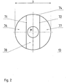
- the structure 13 has, as three sections, two identical components 76, 77 which designed as secant-shaped disc sections and made of a magnetic Material are made, and a connecting element 78, which is used as a strip section is designed with two parallel edges 71 b, 72 b and a non-magnetic or low-magnetic material is made and between the components 76, 77 is located.
- the components 76, 77 and the connecting element 78 are on their contact surfaces or edges 71, 72 firmly connected and form one circular plate.
- the components 76, 77 thus have a circular arc Outer contour 91 and a secant edge 71 a / 72 a.
- the connecting element 78 with the parallel longer edges 71 b, 72 b is on its narrow side edges 74 arcuate; these complement each other with the outer edges 91 to form the circle of the outer Contact piece circumference contour.
- the pole pieces 84, 85 are each made of four identical magnetic field amplifier plates 82 composed of the width B1, which is approximately one third of the diameter D corresponds.
- the magnetic field amplifier plates 82 have the same Contour and thickness as the components 76, 77 and are congruent on each other.
- pole pieces 84, 85 One side of the pole pieces 84, 85 is congruent with the components 76, 77 arranged one above the other and firmly connected to it.
- the contact layer 90 On the pole pieces 84, 85 opposite side of the structure 13 is the contact layer 90, which coincides with one of its pane sides on the structure 13 located and firmly connected to it.
- the complete contact piece 14 has the same cylindrical structure Diameter D, namely first the contact layer 90 with a disc-shaped Structure, for example made of CuCr, then the structure 13 and, on the components 76, 77 arranged, the disc section-like pole pieces 84, 85.
- the cylindrical Construction is therefore only incomplete at one point, namely between the two pole pieces 84, 85, since there are no strip sections that match the respective Complement disk section-like pole pieces 84, 85 to a complete disk shape would.
- the structure 13 mechanically stabilizes the contact piece 14 and connects at the same time the contact layer 90 and the pole pieces 84, 85 to the contact piece 14.
- the connecting element 78 has a circular opening 95 which is used for receiving a contact carrier 96 is used.
- Fig. 2 is the disc-shaped structure 13 for mechanical reinforcement of the contact piece 14 shown in plan view.
- the disk-shaped structure 13 has in this View a circular surface 74 with center M and has three sections.
- the two components 76, 77 consist for example of the steel ST37, and intermediate strip section, the connecting element 78, for example non-magnetic stainless steel.
- the width of the strip section corresponds about 1/3 of the diameter D and is limited by two surfaces that are parallel opposite and at the same time the contact surfaces 71, 72 with the components Are 76.77. These two contact surfaces 71, 72 are in the top view as parallel chords the circular area.
- the two components 76, 77 are on the contact surfaces 71, 72 joined together with the connecting element 78 with a firm, resilient connection, for example by means of laser welding, electron beam welding or Soldering.
- the field amplifier plates 82 can be made of magnetic sheet metal or Tapes.
- the different thicknesses of the materials used play only a subordinate role for the function of the pole pieces 84, 85
- the number of connections to be established advantageously decreases with the increase the thickness of the material used.
- field amplifier plates made from such a thick piece of sheet metal are that they serve as pole pieces 84, 85 and at the same time the disc sections replace. In this case, only the strip section with the field amplifier plates is left 28 connected according to the invention.
- FIG. 3 shows a second disk-shaped structure 12 for mechanical stabilization a contact piece in which a horseshoe-shaped pole piece is provided, in Top view.
- the second disk-shaped structure 12 has an approximately horseshoe shape Section 60 and another section 62, which is exactly in this view add to a circular area. At their contact surface the horseshoe-shaped Section 60 and the further section 62 with one of the aforementioned connection techniques firmly connected.
- the horseshoe-shaped section 60 is made of magnetic Material and intended for it on one of its horseshoe-shaped sides with a Pole piece to be connected or the horseshoe shaped section is itself as Pole piece provided and therefore designed accordingly.
- the further section 62 is made of a non-magnetic or low magnetic material and acts as described in Case of a contact piece with two pole pieces as a connecting element, mechanically stabilizing.
- the middle breakthrough has the same reference number as 1 and 2.
Landscapes
- Non-Reversible Transmitting Devices (AREA)
Abstract
Description
- Fig. 1
- eine Schnittansicht durch ein Kontaktstück mit zwei Polstücken aus Feldverstärkerplatten, entsprechend Schnittlinie I-I der Fig. 2
- Fig. 2
- eine scheibenförmige Struktur zur mechanischen Stabilisierung eines Kontaktstückes in Draufsicht, und
- Fig. 3
- eine zweite scheibenförmige Struktur zur mechanischen Stabilisierung eines Kontaktstückes bei dem ein hufeisenförmiges Polstück vorgesehen ist, in Draufsicht.
Claims (10)
- Kontaktstück (14) für Axialmagnetfeldanwendungen in einer Vakuumkammer, mit wenigstens einem Polstück (84, 85), einer Kontaktschicht (90) sowie einer Struktur (13) zur mechanischen Verstärkung des Kontaktstückes (14), dadurch gekennzeichnet, daß die Struktur (13) wenigstens ein Bauelement (76, 77) aus einem magnetischen Werkstoff sowie ein Verbindungselement (78) aus einem unmagnetischen oder gering magnetischen Werkstoff aufweist, wobei das Verbindungselement (78) fest mit dem wenigstens einen Bauelement (76, 77) verbunden ist und daß das wenigstens eine Bauelement (76, 77) sowie das Verbindungselement (78) so einander zugeordnet sind, daß ein magnetischer Kurzschluß zwischen den verbundenen Bereichen des einen oder zwischen den wenigstens zwei Bauelementen (76, 77) vermieden ist.
- Kontaktstück nach Anspruch 1, dadurch gekennzeichnet, daß die Struktur (13) eine Platte ist.
- Kontaktstück nach Anspruch 1, dadurch gekennzeichnet, daß das wenigstens eine Bauelement (76, 77) der Struktur zu wenigstens einem Polstück (84, 85) geformt sowie zwei Bereiche eines oder die wenigstens zwei Polstücke (84, 85) durch das Verbindungselement (78) fest verbunden sind.
- Kontaktstück nach einem der vorgenannten Ansprüche, dadurch gekennzeichnet, daß das wenigstens eine Polstück (84, 85) mittels mehrerer plattenartiger Bauteile aufgebaut ist, die mit jeweils einem zwischen zwei zu verbindenden plattenartige Bauteile gebrachten Lot verbunden werden, wobei die plattenartigen Bauteile aus einem magnetischem Werkstoff hergestellt sind.
- Kontaktstück nach Anspruch 4, dadurch gekennzeichnet, daß die plattenartigen Bauteile aus magnetischem Blech hergestellt sind, beziehungsweise geschnitten, gestanzt oder gepreßt sind.
- Kontaktstück nach Anspruch 4, dadurch gekennzeichnet, daß die plattenartige Bauteile aus magnetischem Bandmaterial hergestellt sind, beziehungsweise geschnitten, gestanzt oder gepreßt sind.
- Kontaktstück nach einem der vorgenannten Ansprüche, dadurch gekennzeichnet, daß die Platte aus plattenartigen Bauteilen und einem Verbindungselement hergestellt ist, die unterschiedliche Dicken aufweisen, wobei die Platte auf einer Seite plan ist.
- Kontaktstück nach einem der vorgenannten Ansprüche, dadurch gekennzeichnet, daß das wenigstens eine Polstück (84, 85) ein sog. Grünling, ein aus zumindest teilweise magnetischem Pulver gepreßtes, formbeständiges Bauteil, ist.
- Kontaktstück nach einem der vorgenannten Ansprüche, dadurch gekennzeichnet, daß das wenigstens eine Bauelement (76, 77) sowie das Verbindungselement (78) der Struktur (13) durch eine Verbindungstechnik zusammengefügt sind, die eine ausreichend hohe mechanische und thermische Festigkeit der Verbindung gewährleistet, wobei die Verbindungstechnik beispielsweise Laserschweißen, Elektronenstrahl-schweißen, Löten oder gleichartige Verbindungstechnik sein kann.
- Kontaktstück nach einem der vorgenannten Ansprüche, dadurch gekennzeichnet, daß das Verbindungselement (78) mittig eine Aushebung zur Aufnahme eines Kontaktträgers (96) aufweist.
Applications Claiming Priority (4)
| Application Number | Priority Date | Filing Date | Title |
|---|---|---|---|
| DE19954949 | 1999-11-16 | ||
| DE19954949 | 1999-11-16 | ||
| DE10040297 | 2000-08-17 | ||
| DE10040297A DE10040297A1 (de) | 1999-11-16 | 2000-08-17 | Kontaktstück für Axialmagnetfeldanwendungen in einer Vakuumkammer |
Publications (1)
| Publication Number | Publication Date |
|---|---|
| EP1102288A1 true EP1102288A1 (de) | 2001-05-23 |
Family
ID=26006730
Family Applications (1)
| Application Number | Title | Priority Date | Filing Date |
|---|---|---|---|
| EP00123895A Withdrawn EP1102288A1 (de) | 1999-11-16 | 2000-11-03 | Kontaktstück für Axialmagnetfeldanwendungen in einer Vakuumkammer |
Country Status (1)
| Country | Link |
|---|---|
| EP (1) | EP1102288A1 (de) |
Citations (3)
| Publication number | Priority date | Publication date | Assignee | Title |
|---|---|---|---|---|
| US4504711A (en) * | 1982-02-23 | 1985-03-12 | Siemens Aktiengesellschaft | Vacuum switching tube having magnetic field electrodes |
| US4675483A (en) * | 1984-09-10 | 1987-06-23 | Siemens Aktiengesellschaft | Contact arrangement for vacuum switches |
| DE19746316A1 (de) * | 1997-10-21 | 1999-04-22 | Abb Patent Gmbh | Axialmagnetfeldkontaktstück für eine Vakuumkammer und Verfahren zur Herstellung desselben |
-
2000
- 2000-11-03 EP EP00123895A patent/EP1102288A1/de not_active Withdrawn
Patent Citations (3)
| Publication number | Priority date | Publication date | Assignee | Title |
|---|---|---|---|---|
| US4504711A (en) * | 1982-02-23 | 1985-03-12 | Siemens Aktiengesellschaft | Vacuum switching tube having magnetic field electrodes |
| US4675483A (en) * | 1984-09-10 | 1987-06-23 | Siemens Aktiengesellschaft | Contact arrangement for vacuum switches |
| DE19746316A1 (de) * | 1997-10-21 | 1999-04-22 | Abb Patent Gmbh | Axialmagnetfeldkontaktstück für eine Vakuumkammer und Verfahren zur Herstellung desselben |
Similar Documents
| Publication | Publication Date | Title |
|---|---|---|
| DE2947090C2 (de) | ||
| DE2852414C2 (de) | Elektrischer Vakuumschalter | |
| DE4002933C2 (de) | ||
| DE112009001937T5 (de) | Schichttransformator für DC/DC-Umwandler | |
| DE69420602T2 (de) | Vakuumlastschalter, Elektrodenanordnung für Vakuumlastschalter und Verfahren zu dessen Herstellung | |
| DE3143336A1 (de) | Halbleitergleichrichterbaueinheit | |
| EP1844486B1 (de) | Verfahren zur herstellung eines kontaktstückes, sowie kontaktstück für eine vakuumschaltkammer selbst | |
| DE102011080468A1 (de) | Kontaktträger eines Schaltkontaktes für ein elektromechanisches Schaltgerät | |
| EP0073925A1 (de) | Kontaktanordnung für Vakuumschalter | |
| EP1102288A1 (de) | Kontaktstück für Axialmagnetfeldanwendungen in einer Vakuumkammer | |
| EP0143735B1 (de) | Kontaktanordnung für eine Vakuumschaltröhre | |
| EP0240769B1 (de) | Steuerscheibe für Bildwiedergabevorrichtungen | |
| EP0125530A2 (de) | Klystrode mit hoher Verstärkung | |
| DE10040297A1 (de) | Kontaktstück für Axialmagnetfeldanwendungen in einer Vakuumkammer | |
| EP0162801B1 (de) | Kontaktanordnung für einen Vakuumschalter | |
| DE758108C (de) | Kontaktanordnung fuer elektrische Schaltgeraete | |
| EP0088040A1 (de) | Vakuumschaltröhre mit einem als Feldwicklung dienenden Ring | |
| EP1111631B1 (de) | Verfahren zur Herstellung eines Kontaktstückrohlings und eines Kontaktstückes sowie ein Kontaktstückrohling, ein Kontaktstück und eine Kontaktstückanordnung für Axialmagnetfeldanwendungen in einer Vakuumkammer | |
| EP0481993B1 (de) | Kontaktanordnung für ein wechsler-relais | |
| DE2258922B2 (de) | Magnetisch betätigbarer, abgeschlossener Kontakt und Anordnung desselben | |
| DE1200951B (de) | Halbleiteranordnung | |
| DE2846635A1 (de) | Funkenstreckenanordnung | |
| EP1166299B1 (de) | Schaltkontakt für elektrische schaltgeräte | |
| EP0187951A1 (de) | Schaltkontakt für eine Vakuumschaltröhre | |
| DE19848930C2 (de) | Präzisionswiderstand |
Legal Events
| Date | Code | Title | Description |
|---|---|---|---|
| PUAI | Public reference made under article 153(3) epc to a published international application that has entered the european phase |
Free format text: ORIGINAL CODE: 0009012 |
|
| AK | Designated contracting states |
Kind code of ref document: A1 Designated state(s): DE FR GB IT NL |
|
| AX | Request for extension of the european patent |
Free format text: AL;LT;LV;MK;RO;SI |
|
| RAP1 | Party data changed (applicant data changed or rights of an application transferred) |
Owner name: ABB PATENT GMBH |
|
| 17P | Request for examination filed |
Effective date: 20011121 |
|
| AKX | Designation fees paid |
Free format text: DE FR GB IT NL |
|
| 17Q | First examination report despatched |
Effective date: 20030123 |
|
| STAA | Information on the status of an ep patent application or granted ep patent |
Free format text: STATUS: THE APPLICATION IS DEEMED TO BE WITHDRAWN |
|
| 18D | Application deemed to be withdrawn |
Effective date: 20030603 |