EP0125530A2 - Klystrode mit hoher Verstärkung - Google Patents
Klystrode mit hoher Verstärkung Download PDFInfo
- Publication number
- EP0125530A2 EP0125530A2 EP84104504A EP84104504A EP0125530A2 EP 0125530 A2 EP0125530 A2 EP 0125530A2 EP 84104504 A EP84104504 A EP 84104504A EP 84104504 A EP84104504 A EP 84104504A EP 0125530 A2 EP0125530 A2 EP 0125530A2
- Authority
- EP
- European Patent Office
- Prior art keywords
- resonator
- klystrode
- hollow
- phase
- tuning
- Prior art date
- Legal status (The legal status is an assumption and is not a legal conclusion. Google has not performed a legal analysis and makes no representation as to the accuracy of the status listed.)
- Withdrawn
Links
- 238000005457 optimization Methods 0.000 claims abstract description 3
- 230000008878 coupling Effects 0.000 claims description 2
- 238000010168 coupling process Methods 0.000 claims description 2
- 238000005859 coupling reaction Methods 0.000 claims description 2
- 238000004519 manufacturing process Methods 0.000 abstract description 2
- 239000002245 particle Substances 0.000 abstract 1
- 230000003321 amplification Effects 0.000 description 2
- 230000003993 interaction Effects 0.000 description 2
- 238000003199 nucleic acid amplification method Methods 0.000 description 2
- 239000003990 capacitor Substances 0.000 description 1
- 229910010293 ceramic material Inorganic materials 0.000 description 1
- 238000010894 electron beam technology Methods 0.000 description 1
- 239000012212 insulator Substances 0.000 description 1
- 238000002372 labelling Methods 0.000 description 1
Images
Classifications
-
- H—ELECTRICITY
- H01—ELECTRIC ELEMENTS
- H01J—ELECTRIC DISCHARGE TUBES OR DISCHARGE LAMPS
- H01J25/00—Transit-time tubes, e.g. klystrons, travelling-wave tubes, magnetrons
- H01J25/02—Tubes with electron stream modulated in velocity or density in a modulator zone and thereafter giving up energy in an inducing zone, the zones being associated with one or more resonators
- H01J25/04—Tubes having one or more resonators, without reflection of the electron stream, and in which the modulation produced in the modulator zone is mainly density modulation, e.g. Heaff tube
-
- H—ELECTRICITY
- H01—ELECTRIC ELEMENTS
- H01J—ELECTRIC DISCHARGE TUBES OR DISCHARGE LAMPS
- H01J25/00—Transit-time tubes, e.g. klystrons, travelling-wave tubes, magnetrons
- H01J25/02—Tubes with electron stream modulated in velocity or density in a modulator zone and thereafter giving up energy in an inducing zone, the zones being associated with one or more resonators
- H01J25/10—Klystrons, i.e. tubes having two or more resonators, without reflection of the electron stream, and in which the stream is modulated mainly by velocity in the zone of the input resonator
- H01J25/14—Klystrons, i.e. tubes having two or more resonators, without reflection of the electron stream, and in which the stream is modulated mainly by velocity in the zone of the input resonator with tube-like electron stream coaxial with the axis of the resonators
Definitions
- the invention relates to a high gain klystrode consisting of a hollow beam tube and an outcoupling resonator.
- Such a klystrode comes from the publication by Preist and Shrader: "The Klystrode - An Unusual transmitting Tube with Potential for UHF-TV" in the magazine 'Proceedings of the IEEE', Vol.70, No.11, November 1982, pages 1318 until 1325 as known.
- the gain with this klystrode is only about 20dB.
- the invention has for its object to provide a power amplifier tube with small dimensions, low manufacturing costs, high gain and very good efficiency (approx. 60%), especially for the VHF / UHF frequency range.
- the hollow beam allowed a tube concept with relatively high perveance beam (P> 2.10 -6 A / V 3/2). This means on the one hand a relatively low operating voltage and on the other hand a relatively steep characteristic curve for the grid modulation. In addition, these measures result in a high gain being achieved with a relatively coarse lattice structure.
- the cavity resonator for generating the RF power is designed as a folded cavity resonator (in-phase or approximately in-phase operation). This achieves a high degree of efficiency ( ⁇ > 60%) with high power amplification.
- the gain is more than 30dB.
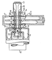
- the klystrode shown in the figure consists essentially of a ring cathode 1 with a heater for generating the hollow beam (electron beam) 10.
- the ring grid 2 is provided for modulating the current of the hollow beam 10.
- two resonator slits 4 and a collector 3 are provided.
- the klystrode is operated in external resonators with tuning slides.
- a pot circle 7 grid-cathode circle
- the folded cavity resonator 5 which is used to generate the RF power, has two independent tuning slides 6 for setting the resonance frequency and the phase position (optimization) between resonator apertures 4/1 (interaction gap) and resonator apertures 4/2 (interaction gap).
- magnets 9 are integrated in the cavity resonator 5.
- a capacitive coupling capacitor 11 is provided in the pot circuit 7.
- the insulator rings made of ceramic material are provided with the reference number 12.
Landscapes
- Microwave Tubes (AREA)
- Particle Accelerators (AREA)
Abstract
Description
- Die Erfindung betrifft eine Klystrode hoher Verstärkung bestehend aus einer Hohlstrahlröhre und einem Auskoppelresonator.
- Eine derartige Klystrode geht aus der Veröffentlichung von Preist und Shrader: "The Klystrode - An Unusual transmitting Tube with Potential for UHF-TV" in der Zeitschrift 'Proceedings of the IEEE', Vol.70, No.11, November 1982, Seiten 1318 bis 1325 als bekannt hervor. Allerdings beträgt die Verstärkung bei dieser Klystrode nur ca. 20dB.
- Aus der DE-PS 19 45 826 ist weiterhin ein konzentrisch aufgebautes Zweikammerklystron mit einer zentral angeordneten Kathode, je einem die Kathode konzentrisch umgebenden Einkoppel- und Auskoppelkreis, die im Bereich der Elektronenströmung gitterförmig durchbrochen sind, und einem Kollektor bekannt, wobei im Bereich der Elektronenströmung der Auskoppelkreis aus einem der Kathode zugewandten Gitter und dem Kollektor besteht, der Einkoppelkreis ein im Vergleich zum Kollektorpotential niedriges Potential aufweist und das Gitter des Auskoppelkreises ein gegenüber dem Potential des Einkoppelkreises abgesenktes Potential aufweist.
- Der Erfindung liegt die Aufgabe zugrunde, eine Leistungsverstärkerröhre mit geringen Abmessungen, niedrigen Herstellkosten, hoher Verstärkung und sehr gutem Wirkungsgrad (ca. 60%), insbesondere für den VHF/UHF-Frequenzbereich, zu schaffen.
- Die Lösung dieser Aufgabe erfolgt durch die im kennzeich- nenden Teil des Anspruchs 1 angegebenen Merkmale.
- Eine vorteilhafte Ausgestaltung der Erfindung ist Gegenstand des Anspruchs 2.
- Durch die Kombination einer gittergesteuerten Hohlstrahlröhre mit einem Doppelspaltresonator werden die höheren Verstärkungswerte und ein besserer Wirkungsgrad erzielt.
- Der Hohlstrahl erlaubt ein Röhrenkonzept mit relativ hoher Strahl-Perveanz (P>2.10-6A/V3/2). Das bedeutet zum einen eine relativ niedrige Betriebsspannung, und zum anderen eine relativ steile Kennlinie für die Gittermodulation. Außerdem haben diese Maßnahmen die Erzielung einer hohen Verstärkung bei einer relativ groben Gitterstruktur zur Folge.
- Der Hohlraumresonator zur Erzeugung der HF-Leistung ist als gefalteter Hohlraumresonator (gleichphasiger bzw. annähernd gleichphasiger Betrieb) ausgebildet. Dadurch wird ein hoher Wirkungsgrad (η>60%) bei großer Leistungsverstärkung erreicht. Die Verstärkung beträgt mehr als 30dB.
- Die Erfindung wird anhand eines in der Figur der Zeichnung schematisch teilweise im Schnitt dargestellten Ausführungsbeispiels weiter erläutert.
- Die in der Figur dargestellte Klystrode besteht im wesentlichen aus einer Ring-Kathode 1 mit Heizer für die Erzeugung des Hohlstrahles (Elektronenstrahles) 10. Das Ring-Gitter 2 ist zur Strommodulation des Hohlstrahles 10 vorgesehen. Außerdem sind zwei Resonatorspalt-Blenden 4 und ein Kollektor 3 vorgesehen. Die Klystrode wird in externen Resonatoren mit Abstimmschiebern betrieben. Hierzu ist ein Topfkreis 7 (Gitter-Kathodenkreis) mit einem Abstimmschieber 8 versehen. Der gefaltete Hohlraumresonator 5, der zur Erzeugung der HF-Leistung dient, weist zwei unabhängige Abstimmschieber 6 zur Einstellung der Resonanzfrequenz und der Phasenlage (Optimierung) zwischen Resonatorblenden 4/1 (Wechselwirkungsspalt) und Resonator-Blenden 4/2 (Wechselwirkungsspalt) auf. Zur Fokussierung des Hohlstrahls 10 sind Magnete 9 in den Hohlraumresonator 5 integriert. Im Topfkreis 7 ist ein kapazitiver Koppelkondensator 11 vorgesehen. Die aus keramischem Material bestehenden Isolatorringe sind mit dem Bezugszeichen 12 versehen.
Claims (2)
Applications Claiming Priority (2)
| Application Number | Priority Date | Filing Date | Title |
|---|---|---|---|
| DE3317788 | 1983-05-16 | ||
| DE19833317788 DE3317788A1 (de) | 1983-05-16 | 1983-05-16 | Klystrode mit hoher verstaerkung |
Publications (2)
| Publication Number | Publication Date |
|---|---|
| EP0125530A2 true EP0125530A2 (de) | 1984-11-21 |
| EP0125530A3 EP0125530A3 (de) | 1986-03-19 |
Family
ID=6199095
Family Applications (1)
| Application Number | Title | Priority Date | Filing Date |
|---|---|---|---|
| EP84104504A Withdrawn EP0125530A3 (de) | 1983-05-16 | 1984-04-19 | Klystrode mit hoher Verstärkung |
Country Status (3)
| Country | Link |
|---|---|
| US (1) | US4567406A (de) |
| EP (1) | EP0125530A3 (de) |
| DE (1) | DE3317788A1 (de) |
Cited By (4)
| Publication number | Priority date | Publication date | Assignee | Title |
|---|---|---|---|---|
| FR2660796A1 (fr) * | 1990-03-09 | 1991-10-11 | Eev Ltd | Appareil a tube a faisceau electronique comportant une cavite d'entree. |
| EP0587481A1 (de) * | 1992-09-11 | 1994-03-16 | Thomson Tubes Electroniques | Radiale Elektronenröhre |
| RU2150766C1 (ru) * | 1999-07-19 | 2000-06-10 | Петров Дмитрий Михайлович | Многолучевой регенеративный усилитель электромагнитных колебаний |
| US6084353A (en) * | 1997-06-03 | 2000-07-04 | Communications And Power Industries, Inc. | Coaxial inductive output tube having an annular output cavity |
Families Citing this family (7)
| Publication number | Priority date | Publication date | Assignee | Title |
|---|---|---|---|---|
| US5317233A (en) * | 1990-04-13 | 1994-05-31 | Varian Associates, Inc. | Vacuum tube including grid-cathode assembly with resonant slow-wave structure |
| US5233269A (en) * | 1990-04-13 | 1993-08-03 | Varian Associates, Inc. | Vacuum tube with an electron beam that is current and velocity-modulated |
| US6127779A (en) * | 1997-03-04 | 2000-10-03 | Litton Systems, Inc. | High voltage standoff, current regulating, hollow electron beam switch tube |
| US5834898A (en) * | 1997-03-04 | 1998-11-10 | Litton Systems, Inc. | High power current regulating switch tube with a hollow electron beam |
| CN104134599A (zh) * | 2014-07-23 | 2014-11-05 | 中国科学院电子学研究所 | 具有双间隙输出腔的感应输出管 |
| CN104134595A (zh) * | 2014-08-19 | 2014-11-05 | 中国科学院电子学研究所 | 一种带状注感应输出管 |
| CN107452581B (zh) * | 2017-06-15 | 2023-06-02 | 湖北汉光科技股份有限公司 | 速调管用阴极热子组合件与热子引出杆连接结构 |
Family Cites Families (8)
| Publication number | Priority date | Publication date | Assignee | Title |
|---|---|---|---|---|
| US2408409A (en) * | 1941-04-08 | 1946-10-01 | Bell Telephone Labor Inc | Ultra high frequency electronic device |
| US2409224A (en) * | 1941-10-23 | 1946-10-15 | Bell Telephone Labor Inc | Oscillator |
| US2409693A (en) * | 1942-01-06 | 1946-10-22 | Westinghouse Electric Corp | Electron discharge device |
| US2840753A (en) * | 1953-02-27 | 1958-06-24 | Westinghouse Electric Corp | Resnatron construction |
| US2958804A (en) * | 1958-05-19 | 1960-11-01 | Eitel Mccullough Inc | Electron beam tube and circuit |
| DE1945826C3 (de) * | 1969-09-10 | 1973-10-04 | Siemens Ag, 1000 Berlin U. 8000 Muenchen | Konzentrisch aufgebautes Zwei kammerklystron |
| US3614518A (en) * | 1970-03-16 | 1971-10-19 | Varian Associates | Microwave tuner having sliding contactors |
| US3921027A (en) * | 1974-09-13 | 1975-11-18 | Joe Shelton | Microwave beam tube |
-
1983
- 1983-05-16 DE DE19833317788 patent/DE3317788A1/de not_active Withdrawn
-
1984
- 1984-04-19 EP EP84104504A patent/EP0125530A3/de not_active Withdrawn
- 1984-05-14 US US06/609,788 patent/US4567406A/en not_active Expired - Fee Related
Cited By (6)
| Publication number | Priority date | Publication date | Assignee | Title |
|---|---|---|---|---|
| FR2660796A1 (fr) * | 1990-03-09 | 1991-10-11 | Eev Ltd | Appareil a tube a faisceau electronique comportant une cavite d'entree. |
| EP0587481A1 (de) * | 1992-09-11 | 1994-03-16 | Thomson Tubes Electroniques | Radiale Elektronenröhre |
| FR2695755A1 (fr) * | 1992-09-11 | 1994-03-18 | Thomson Tubes Electroniques | Tube électronique à structure radiale. |
| US6084353A (en) * | 1997-06-03 | 2000-07-04 | Communications And Power Industries, Inc. | Coaxial inductive output tube having an annular output cavity |
| RU2150766C1 (ru) * | 1999-07-19 | 2000-06-10 | Петров Дмитрий Михайлович | Многолучевой регенеративный усилитель электромагнитных колебаний |
| WO2001006532A1 (fr) * | 1999-07-19 | 2001-01-25 | Vetrov, Andrei Alexeevich | Amplificateur regeneratif d'oscillations electromagnetiques a faisceaux multiples |
Also Published As
| Publication number | Publication date |
|---|---|
| DE3317788A1 (de) | 1984-11-22 |
| US4567406A (en) | 1986-01-28 |
| EP0125530A3 (de) | 1986-03-19 |
Similar Documents
| Publication | Publication Date | Title |
|---|---|---|
| DE69016712T2 (de) | Mikrowellengenerator mit einer virtuellen kathode. | |
| DE966270C (de) | Elektronenentladungseinrichtung zur Erzeugung von ultrahochfrequenten Schwingungen | |
| DE854378C (de) | UKW-Verstaerker unter Verwendung einer Wanderfeldroehre | |
| CH224052A (de) | Vorrichtung mit einer Entladungsröhre, in der ein von einer Steuerschwingung in Dichte moduliertes Elektronenbündel erzeugt wird. | |
| EP0125530A2 (de) | Klystrode mit hoher Verstärkung | |
| DE69021290T2 (de) | Mikrowellen-verstärker oder oszillator-anordnung. | |
| DE60311540T2 (de) | Breitbandige gekoppelte Hohlraumresonatorenanordnung mit invertierten Schlitzmoden | |
| DE2743108A1 (de) | Mehrstufiger vertiefter kollektor | |
| DE69700313T2 (de) | Feldemissions-Elektronenkanone mit Kaltkathode | |
| DE1566030B1 (de) | Laufzeitr¦hre, insbesondere Klystron | |
| DE2914533C3 (de) | Rückwärtswellen-Oszillatorröhre | |
| DE2833734C2 (de) | ||
| DE2738644C2 (de) | Kopplungsvorrichtung für Höchstfrequenzröhren | |
| DE2317487C2 (de) | Mehrkammerklystron | |
| CH650878A5 (de) | Hf-trioden-verstaerker mit rotierendem strahl. | |
| DE3208293A1 (de) | Gyrotron | |
| DE1223961B (de) | Elektrische Entladungsanordnung zur Verstaerkung elektromagnetischer Wellen | |
| DE3002495C2 (de) | Oszillator-Klystron | |
| DE2353555A1 (de) | Laufzeitroehre | |
| DE1945826B2 (de) | Konzentrisch aufgebautes zweikammerklystron | |
| DE3126119A1 (de) | Mikrowellen-verstaerkerroehre mit zwei ringresonatoren | |
| DE1121231B (de) | Laufzeitroehre zur Erzeugung von Millimeterwellen mit einer als Leitungsresonator wirkenden Verzoegerungsleitung | |
| DE3045282C2 (de) | ||
| DE672510C (de) | Magnetronroehre mit Kathode, mehreren dazu achsparallelen Anodensegmenten und Hilfselektroden | |
| DE689577C (de) | Mischroehre, bei der die Oszillatoranode aus zwei in der Ebene der Gitterstreben zwischen Oszillatorgitter und erstem Schirmgitter angeordneten Staeben mit flach rechteckigem oder aehnlichem Querschnitt besteht |
Legal Events
| Date | Code | Title | Description |
|---|---|---|---|
| PUAI | Public reference made under article 153(3) epc to a published international application that has entered the european phase |
Free format text: ORIGINAL CODE: 0009012 |
|
| AK | Designated contracting states |
Designated state(s): DE GB |
|
| PUAL | Search report despatched |
Free format text: ORIGINAL CODE: 0009013 |
|
| AK | Designated contracting states |
Kind code of ref document: A3 Designated state(s): DE GB |
|
| 17P | Request for examination filed |
Effective date: 19860428 |
|
| 17Q | First examination report despatched |
Effective date: 19871208 |
|
| STAA | Information on the status of an ep patent application or granted ep patent |
Free format text: STATUS: THE APPLICATION HAS BEEN WITHDRAWN |
|
| 18W | Application withdrawn |
Withdrawal date: 19880421 |
|
| RIN1 | Information on inventor provided before grant (corrected) |
Inventor name: HEYNISCH, HINRICH, DR. DIPL.-PHYS. |