EP0587481A1 - Radiale Elektronenröhre - Google Patents
Radiale Elektronenröhre Download PDFInfo
- Publication number
- EP0587481A1 EP0587481A1 EP93402154A EP93402154A EP0587481A1 EP 0587481 A1 EP0587481 A1 EP 0587481A1 EP 93402154 A EP93402154 A EP 93402154A EP 93402154 A EP93402154 A EP 93402154A EP 0587481 A1 EP0587481 A1 EP 0587481A1
- Authority
- EP
- European Patent Office
- Prior art keywords
- tube according
- cathode
- electronic tube
- cavity
- resonant
- Prior art date
- Legal status (The legal status is an assumption and is not a legal conclusion. Google has not performed a legal analysis and makes no representation as to the accuracy of the status listed.)
- Granted
Links
- 239000012141 concentrate Substances 0.000 claims abstract 2
- 238000010894 electron beam technology Methods 0.000 claims description 21
- WFKWXMTUELFFGS-UHFFFAOYSA-N tungsten Chemical compound [W] WFKWXMTUELFFGS-UHFFFAOYSA-N 0.000 claims description 5
- 229910052721 tungsten Inorganic materials 0.000 claims description 5
- 239000010937 tungsten Substances 0.000 claims description 5
- 230000000994 depressogenic effect Effects 0.000 claims description 3
- 238000005070 sampling Methods 0.000 abstract 1
- 230000008878 coupling Effects 0.000 description 6
- 238000010168 coupling process Methods 0.000 description 6
- 238000005859 coupling reaction Methods 0.000 description 6
- 210000001015 abdomen Anatomy 0.000 description 2
- 229910052788 barium Inorganic materials 0.000 description 2
- 239000000919 ceramic Substances 0.000 description 2
- 238000001816 cooling Methods 0.000 description 2
- 230000001965 increasing effect Effects 0.000 description 2
- 230000001939 inductive effect Effects 0.000 description 2
- OKTJSMMVPCPJKN-UHFFFAOYSA-N Carbon Chemical compound [C] OKTJSMMVPCPJKN-UHFFFAOYSA-N 0.000 description 1
- 230000003321 amplification Effects 0.000 description 1
- -1 barium aluminates Chemical class 0.000 description 1
- DSAJWYNOEDNPEQ-UHFFFAOYSA-N barium atom Chemical compound [Ba] DSAJWYNOEDNPEQ-UHFFFAOYSA-N 0.000 description 1
- 230000007423 decrease Effects 0.000 description 1
- 230000003247 decreasing effect Effects 0.000 description 1
- 238000007872 degassing Methods 0.000 description 1
- 238000000605 extraction Methods 0.000 description 1
- 239000012530 fluid Substances 0.000 description 1
- 229910002804 graphite Inorganic materials 0.000 description 1
- 239000010439 graphite Substances 0.000 description 1
- 239000000463 material Substances 0.000 description 1
- 229910052751 metal Inorganic materials 0.000 description 1
- 239000002184 metal Substances 0.000 description 1
- 238000003199 nucleic acid amplification method Methods 0.000 description 1
- 230000010355 oscillation Effects 0.000 description 1
- 230000003071 parasitic effect Effects 0.000 description 1
- 238000007789 sealing Methods 0.000 description 1
- 238000009423 ventilation Methods 0.000 description 1
Images

Classifications
-
- H—ELECTRICITY
- H01—ELECTRIC ELEMENTS
- H01J—ELECTRIC DISCHARGE TUBES OR DISCHARGE LAMPS
- H01J25/00—Transit-time tubes, e.g. klystrons, travelling-wave tubes, magnetrons
- H01J25/02—Tubes with electron stream modulated in velocity or density in a modulator zone and thereafter giving up energy in an inducing zone, the zones being associated with one or more resonators
- H01J25/04—Tubes having one or more resonators, without reflection of the electron stream, and in which the modulation produced in the modulator zone is mainly density modulation, e.g. Heaff tube
Definitions
- the present invention relates to electronic vacuum tubes used in particular as power amplifiers in the UHF band.
- the first type includes electron beam amplitude modulation tubes and the second type includes electron beam speed modulation tubes electrons.
- Amplitude modulation tubes are for example triodes or tetrodes while electron beam speed modulation tubes are klystrons or traveling wave tubes.
- tetrode-type grid tubes operate at the upper limit of their frequency band with a gain of around 15 dB and an efficiency of around 50% in common amplification.
- the efficiency considered is the ratio of the power delivered at the output during the synchronization pulse to the average power supplied to the transmitter in G standard.
- Tubes of the klystron type are characterized by a high gain of the order of 40 dB and by a low efficiency of the order of 25% by taking the same criteria.
- IOT Inductive Output Tube
- This tube includes an electron gun with a cathode, an anode and a modulation grid.
- a modulation voltage is applied between the grid and the cathode through a resonant input cavity tuned to a desired frequency.
- the electrons generated by the cathode emerge from the grid in packets and converge on the axis of the beam.
- the beam then passes through an output resonant cavity.
- the beam electrons give up their energy to the exit cavity. This energy is extracted by coupling and directed to a user device such as an antenna.
- the electrons are collected in a collector downstream of the outlet cavity.
- This tube has an axial structure like the klystron and not a radial structure like the tetrode. This axial structure and the nature of the materials used significantly limit the performance of the IOT.
- the cathode used in IOTs as in klystrons is generally made of porous tungsten impregnated with barium aluminates. This cathode operates around 1020 ° C. At this temperature, the barium evaporates and settles on the grid which in turn becomes emissive. The emitted electron beam is disturbed and the life of the tube is greatly reduced. This lifespan can be of the order of 600 hours, whereas one could expect a lifespan of the order of 25,000 hours.
- the operating temperature of the cathode can be reduced, but the density of current emitted and therefore the power of the IOT is limited. If we want to increase the density of emitted current, we would have to increase the surface of the cathode.
- the cathode and the grid are hemispherical. When the grid is large, we observe a non-uniform temperature of its bars: they are much hotter in the center than at the periphery because they cool by conduction. The hot part of the grid emits, the electron beam is then disturbed and the lifetime is reduced.
- the proposed solutions each have their drawbacks and they lead in any case to a limitation of the power of the IOT.
- the present invention proposes to produce an electronic vacuum tube which can operate with a satisfactory lifetime at high power.
- This tube instead of having an axial structure has a radial structure.
- the electron beam emitted is no longer linear but has the shape of a flat radial sheet.
- the tube according to the invention comprises a cathode emitting electrons towards a collector, means for focusing the electrons and an output cavity coupled to the beam to take electromagnetic energy therefrom.
- the cathode is generally with symmetry of revolution about an axis, the electron beam is radial and is focused by the focusing means in a plane substantially normal to the axis of symmetry of the cathode.
- the outlet cavity is coaxial with the cathode.
- the cathode can be cylindrical or in a torus portion. It is advantageously made of thoriated tungsten.
- a grid surrounds the cathode to modulate the emission of electrons.
- the cathode-grid space is part of a resonant modulation cavity into which a modulation voltage is injected.
- the focusing means can be poloidal coils or permanent magnets. They are located on either side of the beam plane.
- the collector is mounted coaxially around the axis of the cathode. He may be depressed.
- a series of radial fins normal to the plane of the beam can be mounted between the cathode and the first resonant cavity reached by the beam.
- Another series of fins can be provided before the collector.
- the fins of a series are preferably in an odd number.
- Means are provided to avoid a collision between the electrons and the fins.
- At least one of the resonant cavities can be coupled to an auxiliary cavity.
- One or more resonant cavities can be tunable in frequency.
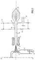
- FIG. 1 schematically represents an electronic tube according to the invention.
- This tube has a symmetry of revolution around an axis XX '.
- a cathode 1 which emits electrons and around a grid 2.
- the space between cathode 1 and grid 2 is part of a resonant modulation cavity 3.
- a voltage modulation 5 is applied in the resonant modulation cavity 3.
- the modulation resonant cavity 3 is dimensioned in ⁇ / 4 or 3 ⁇ / 4. ( ⁇ represents the resonance wavelength of the cavity).
- a tuning piston 4 can be used to tune the resonant modulation cavity 3 to a desired frequency. This piston 4 is located overall at a voltage node of the resonant circuit thus formed.
- the cathode 1 can be produced with a mesh of thoriated tungsten heated directly or indirectly.
- Grid 2 can be made of pyrolitic graphite. These elements are comparable to those used in conventional tetrodes. The pollution of the grid that was observed in the IOTs is thus eliminated.
- the grid 2 and the cathode 1 can be conventionally cylindrical. To facilitate focusing of the emitted electron beam, it is conceivable that the cathode 1 and the grid 2 have the shape of a concave portion of a torus. This variant is shown in FIG. 2. The fact of using a cylindrical or toroidal cathode makes it possible to produce a cathode of large area and therefore to produce a power tube.
- the cathode 1 and the grid 2 are generally brought to a negative high voltage.
- the cathode 1 emits electrons radially with respect to the axis XX '.
- the electrons grouped in packets form a radial beam t3.
- This beam 13 is attracted to an anode 6 brought to a less negative potential than that of the cathode 1.
- the anode 6 is formed by two rings located on either side of the plane of the electron beam. Focusing means are provided so that the beam is concentrated in a plane normal to the axis XX 'of the cathode.
- These focusing means are first of all the electrostatic optics of the grid. To improve the concentration of electrons, it is possible to provide poloidal coils 7 or permanent magnets on either side of the plane of the electron beam. The thickness of the electron beam measured along the axis XX 'is less than the emissive height of the cathode 1.
- the electron beam 13 then passes through an output resonant coaxial cavity 8.
- the two coils of the anode 6 form a sliding space 14 which penetrates into the cavity 8.
- the interior of the cavity 8 is coupled to the electron beam 13 by annular coupling openings 9. These openings, two in number, are located on either side of the plane of the electron beam 13.
- the electrons exit the decelerated exit cavity and are collected in a collector 10 coaxial with the axis XX ', in the form of for example.
- This collector 10 will preferably be cooled, for example, by forced ventilation or by circulation of a fluid.
- the output cavity 8 resonates on a frequency which can be adjusted by means of a tuning device 11.
- these are two movable pistons 11 parallel to the plane of the beam located on either side of the plane of the electron beam.
- the outlet cavity 8 is preferably dimensioned in ⁇ / 2, that is to say that the pistons are spaced by ⁇ / 2 and are located on a tension node.
- the electron beam is located at a voltage belly. There is then as good a coupling as possible between the cavity and the beam.
- the electron beam gives up energy to the output cavity 8 and this energy is extracted by appropriate means. It can be a pallet 12 as in FIG. 1. This energy is transmitted to a user device such as an antenna for example.
- the outlet cavity 8 is coupled to an auxiliary cavity 20.
- the coupling between the two cavities can be capacitive as in FIG. 2 or inductive.
- the energy is extracted at the level of the auxiliary cavity 20.
- the auxiliary cavity will preferably be dimensioned in ⁇ / 2 and the energy extraction will be done near a tension belly if the coupling output is capacitive.
- radial fins 22 may be desirable to stiffen the mechanical structure of the tube and to limit the emergence of parasitic oscillations in guided mode to divide the space between the cathode 1 and the outlet cavity 9 by radial fins 22 substantially normal to the plane of the beam 13. Their number will preferably be odd, for example three, five or more. So that these fins 22 are not bombarded by the electrons of the beam 13, we will arrange for the cathode 1 to have non-emissive zones opposite the radial fins. He can be interesting to also place radial fins 23 between the outlet cavity 8 and the manifold 10. These fins 23 will preferably be aligned with those located between the cathode 1 and the outlet cavity 8. These fins 22, 23 will advantageously be made of metal .
- an electrically insulating part 24 for mechanically holding the anode 6 and the grid 2 while electrically insulating them.
- the anode 6 as well as the outlet cavity 8 are generally brought to ground.
- This part 24 is here conical in shape and can be made of ceramic.
- the interior of the tube is conventionally subjected to vacuum. Sealing can be ensured inside the outlet cavity by two annular windows 25 located on either side of the plane of the electron beam 13. These windows 25 allow electromagnetic energy but not air to pass .
- the collector 10 can be of the depressed type. This means that it is brought to a potential intermediate between the potential of the outlet cavity 8 and the potential of the cathode 1. Annular ceramic pieces 26 are provided to electrically isolate the collector 10 from the outlet cavity 8. In decreasing the potential of the collector compared to that of the outlet cavity, the speed of the electrons entering the collector and therefore the density of heat to be evacuated through the wall of the collector is reduced.
- the tube according to the invention can provide significant power since the cathode can have a large emissive surface.
- the electron beam instead of being long and thin, substantially cylindrical as in klystrons and IOTs, is now radial, substantially disc-shaped.
- the electrons generated by the cathode diverge in the plane of the disc.
- the electron density decreases with distance from the cathode. Due to the low density beam, the coupling with the output cavity is improved and the collector is subjected to a reduced power density.
- the collector can work reliably with air cooling.
- the coaxial IOT type tubes used in television transmitters have a collector whose surface is limited. This collector can be cooled by air circulation.
- the density of thermal power to be dissipated being very high, degassing occurs which influences the life of the tube.
- the coaxial collector of the tube according to the invention has a much larger surface area and the reliability of the tube is increased even with air cooling.
Landscapes
- Microwave Tubes (AREA)
Applications Claiming Priority (2)
| Application Number | Priority Date | Filing Date | Title |
|---|---|---|---|
| FR9210841A FR2695755B1 (fr) | 1992-09-11 | 1992-09-11 | Tube électronique à structure radiale. |
| FR9210841 | 1992-09-11 |
Publications (2)
| Publication Number | Publication Date |
|---|---|
| EP0587481A1 true EP0587481A1 (de) | 1994-03-16 |
| EP0587481B1 EP0587481B1 (de) | 1997-06-04 |
Family
ID=9433407
Family Applications (1)
| Application Number | Title | Priority Date | Filing Date |
|---|---|---|---|
| EP19930402154 Expired - Lifetime EP0587481B1 (de) | 1992-09-11 | 1993-09-03 | Radiale Elektronenröhre |
Country Status (3)
| Country | Link |
|---|---|
| EP (1) | EP0587481B1 (de) |
| DE (1) | DE69311238T2 (de) |
| FR (1) | FR2695755B1 (de) |
Cited By (6)
| Publication number | Priority date | Publication date | Assignee | Title |
|---|---|---|---|---|
| FR2728386A1 (fr) * | 1994-12-20 | 1996-06-21 | Thomson Tubes Electroniques | Tube electronique a grille a performances ameliorees |
| EP0883152A3 (de) * | 1997-06-03 | 1998-12-16 | Communications & Power Industries, Inc. | Coaxiale Röhre mit induktivem Ausgang |
| WO2002015218A1 (de) * | 2000-08-17 | 2002-02-21 | Gesellschaft für Schwerionenforschung mbH | Vorrichtung und verfahren zur ionenstrahlbeschleunigung und zur elektronenstrahlimpulsformung und -verstärkung |
| DE10040896B4 (de) * | 2000-08-18 | 2005-05-04 | Gesellschaft für Schwerionenforschung mbH | Vorrichtung und Verfahren zur Ionenstrahlbeschleunigung und zur Elektronenstrahlimpulsformung und -verstärkung |
| CN104392880A (zh) * | 2014-11-03 | 2015-03-04 | 中国科学院电子学研究所 | 多信道调谐速调管谐振腔的装架方法 |
| CN113725053A (zh) * | 2021-09-02 | 2021-11-30 | 中国科学院空天信息创新研究院 | 平面级联速调管 |
Citations (4)
| Publication number | Priority date | Publication date | Assignee | Title |
|---|---|---|---|---|
| US3305752A (en) * | 1963-12-06 | 1967-02-21 | Friz Walter | Fast wave crossed field travelingwave tube |
| US3971966A (en) * | 1975-08-14 | 1976-07-27 | The United States Of America As Represented By The Secretary Of The Army | Planar ring bar travelling wave tube |
| GB2119565A (en) * | 1982-04-23 | 1983-11-16 | Raytheon Co | Method of making a cathode electrode and product of such method |
| EP0125530A2 (de) * | 1983-05-16 | 1984-11-21 | Siemens Aktiengesellschaft | Klystrode mit hoher Verstärkung |
-
1992
- 1992-09-11 FR FR9210841A patent/FR2695755B1/fr not_active Expired - Fee Related
-
1993
- 1993-09-03 EP EP19930402154 patent/EP0587481B1/de not_active Expired - Lifetime
- 1993-09-03 DE DE1993611238 patent/DE69311238T2/de not_active Expired - Fee Related
Patent Citations (4)
| Publication number | Priority date | Publication date | Assignee | Title |
|---|---|---|---|---|
| US3305752A (en) * | 1963-12-06 | 1967-02-21 | Friz Walter | Fast wave crossed field travelingwave tube |
| US3971966A (en) * | 1975-08-14 | 1976-07-27 | The United States Of America As Represented By The Secretary Of The Army | Planar ring bar travelling wave tube |
| GB2119565A (en) * | 1982-04-23 | 1983-11-16 | Raytheon Co | Method of making a cathode electrode and product of such method |
| EP0125530A2 (de) * | 1983-05-16 | 1984-11-21 | Siemens Aktiengesellschaft | Klystrode mit hoher Verstärkung |
Non-Patent Citations (2)
| Title |
|---|
| A. S. GILMOUR, JR.: "Microwave tubes", 1986, ARTECH HOUSE, NORWOOD, USA, 195530 * |
| G. FAILLON: "IOTs", LA REVUE TECHNIQUE DE THOMSON - CSF, vol. 23, no. 4, December 1991 (1991-12-01), pages 810 - 815 * |
Cited By (9)
| Publication number | Priority date | Publication date | Assignee | Title |
|---|---|---|---|---|
| FR2728386A1 (fr) * | 1994-12-20 | 1996-06-21 | Thomson Tubes Electroniques | Tube electronique a grille a performances ameliorees |
| EP0718867A1 (de) * | 1994-12-20 | 1996-06-26 | Thomson Tubes Electroniques | Gitterelektronenröhre mit verbesserter Leistung |
| EP0883152A3 (de) * | 1997-06-03 | 1998-12-16 | Communications & Power Industries, Inc. | Coaxiale Röhre mit induktivem Ausgang |
| US6084353A (en) * | 1997-06-03 | 2000-07-04 | Communications And Power Industries, Inc. | Coaxial inductive output tube having an annular output cavity |
| WO2002015218A1 (de) * | 2000-08-17 | 2002-02-21 | Gesellschaft für Schwerionenforschung mbH | Vorrichtung und verfahren zur ionenstrahlbeschleunigung und zur elektronenstrahlimpulsformung und -verstärkung |
| DE10040896B4 (de) * | 2000-08-18 | 2005-05-04 | Gesellschaft für Schwerionenforschung mbH | Vorrichtung und Verfahren zur Ionenstrahlbeschleunigung und zur Elektronenstrahlimpulsformung und -verstärkung |
| CN104392880A (zh) * | 2014-11-03 | 2015-03-04 | 中国科学院电子学研究所 | 多信道调谐速调管谐振腔的装架方法 |
| CN113725053A (zh) * | 2021-09-02 | 2021-11-30 | 中国科学院空天信息创新研究院 | 平面级联速调管 |
| CN113725053B (zh) * | 2021-09-02 | 2024-03-26 | 中国科学院空天信息创新研究院 | 平面级联速调管 |
Also Published As
| Publication number | Publication date |
|---|---|
| DE69311238T2 (de) | 1997-09-18 |
| FR2695755B1 (fr) | 1994-10-28 |
| DE69311238D1 (de) | 1997-07-10 |
| FR2695755A1 (fr) | 1994-03-18 |
| EP0587481B1 (de) | 1997-06-04 |
Similar Documents
| Publication | Publication Date | Title |
|---|---|---|
| Kesari et al. | High Power Microwave Tubes: Basics and Trends, Volume 2 | |
| FR2547456A1 (fr) | Tube a faisceau d'electrons module en densite avec un gain accru | |
| FR2527005A1 (fr) | Tube electronique de puissance a grille perfectionne | |
| US11545329B2 (en) | THz vacuum electronic devices with micro-fabricated electromagnetic circuits | |
| EP0587481B1 (de) | Radiale Elektronenröhre | |
| US3471744A (en) | Coaxial magnetron having a segmented ring slot mode absorber | |
| US2789250A (en) | High frequency device | |
| US9196449B1 (en) | Floating grid electron source | |
| Steer et al. | Extended-Interaction Klystron Technology at Millimeter and Submillimeter Wavelengths | |
| US8400225B1 (en) | Photocapacitively tunable electronic device utilizing electrical resonator with semiconductor junction | |
| EP0251830B1 (de) | Mehrfachstrahl-Lasertron | |
| FR2733856A1 (fr) | Cathode pour canon a electrons a grille, grille destinee a etre associee avec une telle cathode et canon a electrons comportant une telle cathode | |
| FR2877489A1 (fr) | Canon a electrons | |
| US3596131A (en) | Cathode secondary emitter for crossed-field tubes | |
| FR2722559A1 (fr) | Four a micro-ondes | |
| WO2009083540A1 (fr) | Protection d'une electrode de tube electronique | |
| CN111383875B (zh) | 一种二次电子倍增膜涂覆在内壁的电磁波发生器 | |
| US3448313A (en) | Efficient radiation cooled beam collector for linear beam devices | |
| US3448325A (en) | Linear beam tube having a beam collector cooled by radiation through an infrared window | |
| US3403352A (en) | Laser having efficient coupling between a phosphor pump source and the laser medium | |
| US3733510A (en) | Electron discharge devices using electron-bombarded semiconductors | |
| EP1680799B1 (de) | Mikrowellenröhre mit geringer störstrahlung | |
| FR2838235A1 (fr) | Dispositif de refroidissement d'un tube electronique | |
| EP1466343A2 (de) | Elektronenröhre mit einem mit einer axialen pumpspitze versehen kollektor | |
| Bell et al. | An 8-mm klystron power oscillator |
Legal Events
| Date | Code | Title | Description |
|---|---|---|---|
| PUAI | Public reference made under article 153(3) epc to a published international application that has entered the european phase |
Free format text: ORIGINAL CODE: 0009012 |
|
| AK | Designated contracting states |
Kind code of ref document: A1 Designated state(s): DE FR GB |
|
| 17P | Request for examination filed |
Effective date: 19940816 |
|
| 17Q | First examination report despatched |
Effective date: 19951228 |
|
| GRAG | Despatch of communication of intention to grant |
Free format text: ORIGINAL CODE: EPIDOS AGRA |
|
| GRAH | Despatch of communication of intention to grant a patent |
Free format text: ORIGINAL CODE: EPIDOS IGRA |
|
| GRAH | Despatch of communication of intention to grant a patent |
Free format text: ORIGINAL CODE: EPIDOS IGRA |
|
| GRAA | (expected) grant |
Free format text: ORIGINAL CODE: 0009210 |
|
| AK | Designated contracting states |
Kind code of ref document: B1 Designated state(s): DE FR GB |
|
| REF | Corresponds to: |
Ref document number: 69311238 Country of ref document: DE Date of ref document: 19970710 |
|
| GBT | Gb: translation of ep patent filed (gb section 77(6)(a)/1977) |
Effective date: 19970807 |
|
| PLBE | No opposition filed within time limit |
Free format text: ORIGINAL CODE: 0009261 |
|
| STAA | Information on the status of an ep patent application or granted ep patent |
Free format text: STATUS: NO OPPOSITION FILED WITHIN TIME LIMIT |
|
| 26N | No opposition filed | ||
| REG | Reference to a national code |
Ref country code: GB Ref legal event code: IF02 |
|
| PGFP | Annual fee paid to national office [announced via postgrant information from national office to epo] |
Ref country code: DE Payment date: 20050902 Year of fee payment: 13 |
|
| PGFP | Annual fee paid to national office [announced via postgrant information from national office to epo] |
Ref country code: GB Payment date: 20060830 Year of fee payment: 14 |
|
| PGFP | Annual fee paid to national office [announced via postgrant information from national office to epo] |
Ref country code: FR Payment date: 20060908 Year of fee payment: 14 |
|
| PG25 | Lapsed in a contracting state [announced via postgrant information from national office to epo] |
Ref country code: DE Free format text: LAPSE BECAUSE OF NON-PAYMENT OF DUE FEES Effective date: 20070403 |
|
| GBPC | Gb: european patent ceased through non-payment of renewal fee |
Effective date: 20070903 |
|
| REG | Reference to a national code |
Ref country code: FR Ref legal event code: ST Effective date: 20080531 |
|
| PG25 | Lapsed in a contracting state [announced via postgrant information from national office to epo] |
Ref country code: FR Free format text: LAPSE BECAUSE OF NON-PAYMENT OF DUE FEES Effective date: 20071001 |
|
| PG25 | Lapsed in a contracting state [announced via postgrant information from national office to epo] |
Ref country code: GB Free format text: LAPSE BECAUSE OF NON-PAYMENT OF DUE FEES Effective date: 20070903 |