EP1101977A2 - Transmission à dérivation de puissance - Google Patents
Transmission à dérivation de puissance Download PDFInfo
- Publication number
- EP1101977A2 EP1101977A2 EP00403209A EP00403209A EP1101977A2 EP 1101977 A2 EP1101977 A2 EP 1101977A2 EP 00403209 A EP00403209 A EP 00403209A EP 00403209 A EP00403209 A EP 00403209A EP 1101977 A2 EP1101977 A2 EP 1101977A2
- Authority
- EP
- European Patent Office
- Prior art keywords
- shaft
- hydraulic
- transmission
- hydraulic member
- converter
- Prior art date
- Legal status (The legal status is an assumption and is not a legal conclusion. Google has not performed a legal analysis and makes no representation as to the accuracy of the status listed.)
- Withdrawn
Links
- 230000005540 biological transmission Effects 0.000 title claims abstract description 96
- 230000002706 hydrostatic effect Effects 0.000 claims abstract description 68
- 230000000903 blocking effect Effects 0.000 claims abstract description 8
- 238000011144 upstream manufacturing Methods 0.000 claims abstract description 7
- 238000009795 derivation Methods 0.000 claims abstract description 3
- 239000003921 oil Substances 0.000 claims description 80
- 230000006978 adaptation Effects 0.000 claims description 38
- 238000006073 displacement reaction Methods 0.000 claims description 29
- 210000000056 organ Anatomy 0.000 claims description 27
- 238000005461 lubrication Methods 0.000 claims description 16
- 230000001105 regulatory effect Effects 0.000 claims description 6
- 230000000295 complement effect Effects 0.000 claims description 3
- 239000010687 lubricating oil Substances 0.000 claims description 3
- 238000005192 partition Methods 0.000 claims description 3
- 238000001816 cooling Methods 0.000 claims description 2
- 230000002093 peripheral effect Effects 0.000 claims description 2
- XLYOFNOQVPJJNP-UHFFFAOYSA-N water Substances O XLYOFNOQVPJJNP-UHFFFAOYSA-N 0.000 abstract 1
- 208000031968 Cadaver Diseases 0.000 description 7
- 235000021183 entrée Nutrition 0.000 description 5
- 239000000969 carrier Substances 0.000 description 4
- 230000008901 benefit Effects 0.000 description 3
- 239000012530 fluid Substances 0.000 description 3
- 230000001050 lubricating effect Effects 0.000 description 3
- 230000005587 bubbling Effects 0.000 description 2
- 230000005465 channeling Effects 0.000 description 2
- 230000000694 effects Effects 0.000 description 2
- 238000005086 pumping Methods 0.000 description 2
- 230000015556 catabolic process Effects 0.000 description 1
- 238000006243 chemical reaction Methods 0.000 description 1
- 230000001276 controlling effect Effects 0.000 description 1
- 230000003247 decreasing effect Effects 0.000 description 1
- 238000006731 degradation reaction Methods 0.000 description 1
- 230000005484 gravity Effects 0.000 description 1
- 230000008676 import Effects 0.000 description 1
- 238000004519 manufacturing process Methods 0.000 description 1
- 238000005507 spraying Methods 0.000 description 1
- 230000009466 transformation Effects 0.000 description 1
Images



Classifications
-
- F—MECHANICAL ENGINEERING; LIGHTING; HEATING; WEAPONS; BLASTING
- F16—ENGINEERING ELEMENTS AND UNITS; GENERAL MEASURES FOR PRODUCING AND MAINTAINING EFFECTIVE FUNCTIONING OF MACHINES OR INSTALLATIONS; THERMAL INSULATION IN GENERAL
- F16H—GEARING
- F16H47/00—Combinations of mechanical gearing with fluid clutches or fluid gearing
- F16H47/02—Combinations of mechanical gearing with fluid clutches or fluid gearing the fluid gearing being of the volumetric type
- F16H47/04—Combinations of mechanical gearing with fluid clutches or fluid gearing the fluid gearing being of the volumetric type the mechanical gearing being of the type with members having orbital motion
-
- F—MECHANICAL ENGINEERING; LIGHTING; HEATING; WEAPONS; BLASTING
- F16—ENGINEERING ELEMENTS AND UNITS; GENERAL MEASURES FOR PRODUCING AND MAINTAINING EFFECTIVE FUNCTIONING OF MACHINES OR INSTALLATIONS; THERMAL INSULATION IN GENERAL
- F16H—GEARING
- F16H37/00—Combinations of mechanical gearings, not provided for in groups F16H1/00 - F16H35/00
- F16H37/02—Combinations of mechanical gearings, not provided for in groups F16H1/00 - F16H35/00 comprising essentially only toothed or friction gearings
- F16H37/06—Combinations of mechanical gearings, not provided for in groups F16H1/00 - F16H35/00 comprising essentially only toothed or friction gearings with a plurality of driving or driven shafts; with arrangements for dividing torque between two or more intermediate shafts
- F16H37/08—Combinations of mechanical gearings, not provided for in groups F16H1/00 - F16H35/00 comprising essentially only toothed or friction gearings with a plurality of driving or driven shafts; with arrangements for dividing torque between two or more intermediate shafts with differential gearing
- F16H37/0833—Combinations of mechanical gearings, not provided for in groups F16H1/00 - F16H35/00 comprising essentially only toothed or friction gearings with a plurality of driving or driven shafts; with arrangements for dividing torque between two or more intermediate shafts with differential gearing with arrangements for dividing torque between two or more intermediate shafts, i.e. with two or more internal power paths
- F16H37/084—Combinations of mechanical gearings, not provided for in groups F16H1/00 - F16H35/00 comprising essentially only toothed or friction gearings with a plurality of driving or driven shafts; with arrangements for dividing torque between two or more intermediate shafts with differential gearing with arrangements for dividing torque between two or more intermediate shafts, i.e. with two or more internal power paths at least one power path being a continuously variable transmission, i.e. CVT
- F16H2037/0866—Power-split transmissions with distributing differentials, with the output of the CVT connected or connectable to the output shaft
-
- F—MECHANICAL ENGINEERING; LIGHTING; HEATING; WEAPONS; BLASTING
- F16—ENGINEERING ELEMENTS AND UNITS; GENERAL MEASURES FOR PRODUCING AND MAINTAINING EFFECTIVE FUNCTIONING OF MACHINES OR INSTALLATIONS; THERMAL INSULATION IN GENERAL
- F16H—GEARING
- F16H37/00—Combinations of mechanical gearings, not provided for in groups F16H1/00 - F16H35/00
- F16H37/02—Combinations of mechanical gearings, not provided for in groups F16H1/00 - F16H35/00 comprising essentially only toothed or friction gearings
- F16H37/06—Combinations of mechanical gearings, not provided for in groups F16H1/00 - F16H35/00 comprising essentially only toothed or friction gearings with a plurality of driving or driven shafts; with arrangements for dividing torque between two or more intermediate shafts
- F16H37/08—Combinations of mechanical gearings, not provided for in groups F16H1/00 - F16H35/00 comprising essentially only toothed or friction gearings with a plurality of driving or driven shafts; with arrangements for dividing torque between two or more intermediate shafts with differential gearing
- F16H37/10—Combinations of mechanical gearings, not provided for in groups F16H1/00 - F16H35/00 comprising essentially only toothed or friction gearings with a plurality of driving or driven shafts; with arrangements for dividing torque between two or more intermediate shafts with differential gearing at both ends of intermediate shafts
- F16H2037/102—Combinations of mechanical gearings, not provided for in groups F16H1/00 - F16H35/00 comprising essentially only toothed or friction gearings with a plurality of driving or driven shafts; with arrangements for dividing torque between two or more intermediate shafts with differential gearing at both ends of intermediate shafts the input or output shaft of the transmission is connected or connectable to two or more differentials
-
- F—MECHANICAL ENGINEERING; LIGHTING; HEATING; WEAPONS; BLASTING
- F16—ENGINEERING ELEMENTS AND UNITS; GENERAL MEASURES FOR PRODUCING AND MAINTAINING EFFECTIVE FUNCTIONING OF MACHINES OR INSTALLATIONS; THERMAL INSULATION IN GENERAL
- F16H—GEARING
- F16H37/00—Combinations of mechanical gearings, not provided for in groups F16H1/00 - F16H35/00
- F16H37/02—Combinations of mechanical gearings, not provided for in groups F16H1/00 - F16H35/00 comprising essentially only toothed or friction gearings
- F16H37/06—Combinations of mechanical gearings, not provided for in groups F16H1/00 - F16H35/00 comprising essentially only toothed or friction gearings with a plurality of driving or driven shafts; with arrangements for dividing torque between two or more intermediate shafts
- F16H37/08—Combinations of mechanical gearings, not provided for in groups F16H1/00 - F16H35/00 comprising essentially only toothed or friction gearings with a plurality of driving or driven shafts; with arrangements for dividing torque between two or more intermediate shafts with differential gearing
- F16H37/10—Combinations of mechanical gearings, not provided for in groups F16H1/00 - F16H35/00 comprising essentially only toothed or friction gearings with a plurality of driving or driven shafts; with arrangements for dividing torque between two or more intermediate shafts with differential gearing at both ends of intermediate shafts
- F16H2037/105—Combinations of mechanical gearings, not provided for in groups F16H1/00 - F16H35/00 comprising essentially only toothed or friction gearings with a plurality of driving or driven shafts; with arrangements for dividing torque between two or more intermediate shafts with differential gearing at both ends of intermediate shafts characterised by number of modes or ranges, e.g. for compound gearing
- F16H2037/106—Combinations of mechanical gearings, not provided for in groups F16H1/00 - F16H35/00 comprising essentially only toothed or friction gearings with a plurality of driving or driven shafts; with arrangements for dividing torque between two or more intermediate shafts with differential gearing at both ends of intermediate shafts characterised by number of modes or ranges, e.g. for compound gearing with switching means to provide two variator modes or ranges
Definitions
- the invention relates to a bypass transmission of power, especially for a motor vehicle.
- the invention relates more particularly to a power bypass transmission, especially for a motor vehicle, of the type which comprises, from upstream to downstream, a input shaft which is coupled to a vehicle engine, a first and second planetary gears, and a spindle output which is coupled to a bridge to drive at least one vehicle wheel, of the type in which first and second elements of the first and second planetary gear trains, including first and second planets, planet carriers and crowns are linked in rotation to each other, to the shaft input, to the output shaft, to a first tree of a controlled hydrostatic converter likely to do vary the reason for the first planetary train, and are related selectively to a second converter shaft hydrostatic likely to vary the reason for the second planetary gear train by interconnection with one or the other of two second elements of the second planetary gear.
- the document FR-2.520.827 describes and represents a example of such a transmission.
- This transmission comprises a first and a second epicyclic trains whose planets are both linked in rotation at the input shaft of the transmission, and of which respectively the planet carriers are both linked in rotation at the output shaft of the transmission.
- a first hydraulic member of a hydrostatic converter is linked to a crown of the first planetary gear, and a second hydraulic member of said hydrostatic converter is capable of being selectively linked in rotation to a crown from the second planetary gear train or from a meshing gable with the output shaft of the transmission.
- the hydraulic components of the hydrostatic converter are, in known manner, axial piston pump motors whose flow rates can be regulated by adjusting the respective inclinations of the plates on which bear the axial pistons of each of the hydraulic organs, so as to allow their operation at regulated speeds and torques.
- transmission is likely to determine two operating modes, including one so-called “coupled output” operating mode for which the second hydraulic member of the hydrostatic converter is linked in rotation to a pinion meshing with the shaft of output of the transmission, and a mode of operation known as “to two adaptation points "for which the second organ of the hydrostatic converter is linked in rotation to the crown of the second planetary gear train.
- the so-called “coupled output” operating mode provides at least one operating point, says “adaptation point”, from the hydrostatic converter for which the first organ is at zero speed to block the crown of the first planetary gear train, and for which the second hydraulic member has zero displacement
- the mode of so-called "two-point adaptation” operation allows to obtain at least two operating points, called adapter, for which one of the hydraulic components is zero speed to block the crown of the first train epicyclic or the crown of the second planetary gear and for which the other hydraulic member is at zero speed.
- the blocking of one or other of the crowns of the first planetary gear train or the second planetary gear allows in particular to establish high transmission ratios.
- the invention proposes a transmission of the type described above eliminating this loss.
- the invention proposes a transmission of the type described above, characterized in that it comprises independent mechanical means for blocking the first and second hydrostatic converter shafts to avoid hydraulic energy losses in said converter hydrostatic.
- the invention also relates to a hydraulic member, especially for a hydrostatic converter of motor vehicle bypass transmission of the type mentioned above.
- This hydraulic member is capable of operating in hydraulic motor-pump and which comprises a shaft and a tilting platform in a controlled manner with which axial pistons are in contact so as to cause, during the rotation of the shaft, their sliding in an interior body of the organ following a course which is determined by the inclination of the plate, the variation of the piston stroke in their chambers determining the variable displacement of the motor-pump.
- organs of this type are used in many devices requiring the transformation of a power mechanical, transmitted through the rotation of the shaft, in hydraulic power, transmitted by the sliding pistons in their chambers.
- hydrostatic converters which can for example be used in transmissions to power bypass for motor vehicles, such as described above.
- the size of the hydraulic components used is a determining criterion of design.
- An internal body of the organ which carries the pistons axial, is mounted fixed relative to a housing of the member hydraulic so that the rotation of the plate causes a reciprocating movement of the pistons in the inner body.
- the pistons are for example resiliently recalled to against the plate and the contact between the ends of the pistons and the plate is a point type contact, or the pistons are free to slide in the inner body of the organ and their ends are held in a groove circular of the plate by a so-called “hydrodynamic" bearing.
- it may be motor-pumps for which the plate is driven in rotation by the shaft while being articulated by a pivot by relation to the body casing, in particular through sliding shoes which are rotatably mounted on a housing of the organ.
- the outer body of the plate which carries a cylinder double acting, is fixed, the end of the cylinder sliding in a circular groove of the plate via a bearing hydrodynamic.
- the inner body which carries the pistons axial, is rotated by the shaft and the ends axial pistons are for example linked to the plate by through ball joints, so that the tilt overall constant of the plate in relation to the housing causes reciprocating movement of pistons in the body interior.
- Such pump motors generally include a single double-acting axial hydraulic cylinder for control of the tilting plate with which the axial pistons are in contact.
- This unique axial hydraulic cylinder is a source of many disadvantages.
- the cylinder to double effect which must operate under a pressure of approximately 20 bars, is particularly bulky, which implies place the double-acting cylinder according to a clearly marked diameter greater than the diameter along which the pistons are arranged, and they make this type of hydraulic member unsuitable for use on a light passenger vehicle.
- the cylinder double effect creates an imbalance which causes problems considerable, since its mass varies according to the amount of oil it contains, and since its inertia varies in depending on the axial position of its piston.
- the invention proposes a hydraulic member comprising control means of the inclination of the tray which are compact and which are dynamically balanced.
- the invention provides a hydraulic member of the type described above, characterized in that the plate of the hydraulic member is controlled in inclination around an axis perpendicular to the axial direction of the shaft of the hydraulic member by at least two double jacks, single acting, axial direction, which are diametrically opposite and which are carried by a body external to the organ hydraulic.
- the rotating elements of such a transmission that is to say in particular the shaft transmission input shaft, the output shaft of the transmission, the first and second planetary gear trains and the deck are arranged inside an oil pan forming tank within which their lubrication is ensured by bubbling.
- a mechanical oil pump driven by a rotating elements, preferably the input shaft of the transmission, draws oil from the oil pan and the pump to right of the rotating elements, from where it is discharged naturally by gravity before falling back to the bottom of the housing oil.
- the high speed operation of the feed oil pump results in a noise level high, which affects the comfort of passengers vehicle.
- the lubrication by bubbling of the elements rotating requires a transmission housing intended to form an oil tank and which is thus particularly bulky.
- the oil pumping requires a supply oil pump high power, both bulky, noisy and consuming a significant fraction of the power of the heat engine.
- the invention proposes a transmission of the type described above for which the feed oil pump is not driven by the shaft transmission input.
- the invention proposes a transmission of the type described above, characterized in that it comprises lubrication means, at least its input shafts and of exit, of the bridge, and of its first and second trains epicyclic, comprising at least one oil pump electric drive.
- Figures 1 and 2 show a set of transmission 10 with power diversion carried out according to the invention.
- the bypass transmission 10 of power comprises an input shaft 12 which is coupled, by example via a clutch 13, to a motor 14 of the vehicle, a first planetary gear 16 and a second planetary gear 18, and an output shaft 20 which is coupled, in particular by means of a shaft 22 for the descent of bridge, to a bridge 24 to drive at least one wheel 26 of the vehicle.
- the first epicyclic train 16 and the second train 18 epicyclic have first elements respectively including a first planetary 28, a first planet carrier 30, and a first crown 32, and second elements including one second sun gear 34, a second planet carrier 36, and a second crown 38.
- first elements of the first planetary gear 16 and second elements of the second planetary gear 18 are permanently linked to each other to the others, to the input shaft 12 of the transmission 10, to the output shaft 20 of the transmission 10, and to a first shaft 40 of a hydrostatic converter 42 for varying the reason for the first planetary gear 16, and some of the second elements of the second epicyclic train 18 are linked selectively a second shaft 44 of the converter 42 hydrostatic to vary the reason for the second train 18 epicyclic by interconnection with one or the other of two of the second elements of the second planetary gear 18.
- the first planetary 28 and the second ring 38 are linked to each other and are linked to the input shaft 12 of the transmission 10
- the first 30 and second 36 planet carriers are linked to each other and are linked to the output shaft 20 of the transmission 10
- the first crown 32 is linked to the first tree 40 of the hydrostatic converter 42.
- interconnection means 46 allow selectively link the first 30 and second 34 planet carriers to the second shaft 44 of the converter 42 hydrostatic or to link the second planetary 34 to second shaft 44 of the hydrostatic converter 42.
- the first ring 32 of the first train 16 epicyclic meshes with an upstream pinion 48 arranged at the end of a primary intermediate shaft 50 of which the other end carries a downstream pinion 52 which meshes with a pinion 54 carried by the first shaft 40 of the converter 42 hydrostatic.
- a sprocket 56 which meshes directly with the second sun gear 34 of the second train 18 epicyclic, and a idler pinion 58, which meshes with a pinion upstream 60 arranged at the end of an intermediate shaft 62 secondary whose other end carries a downstream pinion 64 which meshes with a pinion 66 carried by the output shaft 20, are likely to be selectively interconnected by means of dog clutch 46 on the second shaft 44 of the converter 42 hydrostatic to selectively link the second in rotation shaft 44 of the hydrostatic converter 42 to the second planetary 34 or to the output shaft 20.
- the dog clutch means 46 are in particular consisting of a double dog 68 capable of clutch either the idler gear 56 or the idler gear 58 next two extreme and opposite positions.
- the hydrostatic converter 42 is composed of a first hydraulic member 70 and a second hydraulic member 72, which are associated respectively to the first tree 40 and to the second tree 44 of the converter, which are hydraulically connected to each other, and each of which is likely to operate as a pump or else in hydraulic motor with variable displacement controlled, to transmit a rotational movement, of torque and speed of determined values, of one of first 70 and second 72 hydraulic components to the other of hydraulic components 70, 72 according to the torque and speed of regulated values.
- the first hydraulic member 70 and the second hydraulic member 72 are both controlled by control means (not shown).
- control means of transmission 10 are likely to establish two modes of operation.
- a fraction motive power is taken up by the first organ hydraulic 70, which then operates as a hydraulic pump, on the first planetary gear 16 and is transformed into hydraulic power.
- This hydraulic power is transmitted to the second hydraulic member 72 which restores it to the second planetary gear train 72.
- the control means allow to control the speed and torque values of the first 70 and second 72 hydraulic components by regulating the displacement of these.
- each of the first organ hydraulic 70 and second hydraulic member 72 are motor-pumps which each have an associated shaft 40 and 44 with which a tilting tray is attached on which are supported axial pistons, elastically recalled against the plate, and which slide in a room following a race which is determined by the tilt of the platform, the variation of the piston stroke in their chambers determining the variable displacement of each pump motor.
- control means of transmission 10 are first of all likely to establish a so-called “coupled output” operating mode, in which the double clutch 68 rotates the shaft 44 of the converter 42 hydrostatic to the output shaft 20.
- This mode of operation is used in particular for starting the vehicle and for its operation at reduced speed.
- the output torque is supplied to the shaft 20 output only by the second hydraulic member 72 which is powered by the first hydraulic member 70 and operates at full displacement. Then the rotation speed of the output shaft 20 gradually increases by increase the displacement of the first hydraulic member 70 to a maximum rotation speed.
- the couple of output which results from the addition of the torque supplied to the shaft 20 of output by the second hydraulic member 72 and torque traveling in the two planetary trains 16 and 18, gradually increases to a maximum value which is obtained when the first 70 and second 72 organs both operate at full displacement.
- the speed of rotation speed of rotation of the shaft 20 can then be further increased by reducing the displacement of the second hydraulic member 72.
- the means of transmission control 10 are likely to establish a so-called "two-point adaptation" operating mode, in which the double dog 68 rotates the second shaft 44 of the hydrostatic converter 42 to the second planetary 34.
- This two-point mode of operation allows to establish at least two operating points, called adaptation, for which one of the hydraulic members 70 or 72 is at zero speed to block the first ring 32 or well the second planetary 34 and for which the other organ hydraulic 70 or 72 has zero displacement, and therefore rotates at empty and zero torque.
- the first adaptation point corresponds to the blocking of the first ring 32 by the first hydraulic member 70 while the second hydraulic member 72, which is displacement zero, therefore runs empty and at zero torque.
- This first point of adaptation allows in particular the changeover from operating mode called “coupled output” to so-called “two-point adaptation” operating mode, the double dog 68 passing from the position in which it links in rotation of the shaft 44 from the hydrostatic converter 42 to the shaft 20 output to that in which it rotates the second shaft 44 of the hydrostatic converter 42 to the second planetary 34.
- increasing the speed of rotation of the output shaft 20 is obtained by reducing the displacement of the first organ hydraulic 70 and increasing that of the second member hydraulic 72.
- the second hydraulic member 72 operates then in hydraulic pump to supply the first organ hydraulic 70 which works as a motor.
- Transmission 10 then reaches a second point adaptation for which the second hydraulic member 72 is at full displacement and zero speed to block the second planetary 34 of the second planetary gear 18 while the first hydraulic member 70 has zero displacement and rotates therefore empty at zero torque.
- the invention proposes a transmission 10 of the type described above, which has independent mechanical blocking means first 40 shaft and second shaft 44 of converter 42 hydrostatic to avoid losses of hydraulic energy in said hydrostatic converter 42.
- the transmission 10 comprises a first brake 74 which acts on the first ring 32 and a second brake 76 which acts on the converter output shaft 44 hydrostatic, and more particularly on the idler gear 56 which is carried by the output shaft 44 of the converter 42.
- the first brake 74 which is shown in FIG. 1 and second brake 76, which is shown in Figure 2, are both controlled by the control means.
- the control means activate the first brake 74, in the coupled output operating mode or in the two-point mode of operation, when the hydrostatic converter 42 is at the first point adaptation for which the first hydraulic member 70 is at zero speed
- the control means activate the second brake 76, in two-point operating mode adaptation, when the hydrostatic converter 42 is at second adaptation point for which the second organ hydraulic 72 is at zero speed.
- first brake 74 and second brake 76 All known means of realization can be used for the realization of the first brake 74 and second brake 76.
- first brake 74 is preferably a brake band and the second brake 76 is preferably a brake disk.
- the invention therefore advantageously makes it possible to benefit of a power derivation transmission 10 of excellent yield.
- FIGS. 3 to 5 show a casing 144 of a member 30 forming a pump motor for a transmission 10 according to the invention.
- the housing 144 receives an external body 146 fixed, which may in particular have come integrally with the casing 144 as illustrated more particularly in FIG. 5.
- a bore 147 arranged inside the body 146 outside, receives a body interior 148 which is therefore mounted to rotate relative to the casing 144.
- An input / output shaft 150 is mounted for rotation in the outer body 146 and in particular carries the body interior 148.
- the input / output shaft 150 of the member 130 is rotatably mounted in the outer body 146 by via a bearing 152.
- the other end of the shaft 150 is carried by a bearing 154 of the transmission 10, which is shown in Figure 1 or 2.
- the input / output shaft 150 rotates the body interior 148 by means of grooves 156, which inner body 148 rotates a tilting table 58 substantially disc-shaped.
- connection of the plate 158 to the body interior 148 is a constant velocity joint type connection, which allows both the drive of the plate 158 by the shaft 150 and its inclination relative to it.
- Any known means of realization of this link can be used for realization of the invention, however it has been shown in Figures 3 and 4 in the form of a ball joint 160 comprising grooves 62 interposed between the internal body 148 and the plate 158.
- the plate 158 is also rotatably mounted relative to the housing 144 around an axis A which is perpendicular to the direction axial of the shaft 150.
- a flange device 164 of the platform is slidably mounted between two skids 166 carried by the ends of two shafts 168 which are mounted to rotate along the axis A, in particular by through bearings 170 arranged in the casing 144 of on either side of tray 158.
- FIG. 3 shows a plane P 0 of the corresponding plate 158 at a zero inclination of the latter relative to its rest position, that is to say an inclination for which it is substantially perpendicular to the shaft 150
- FIG. 4 shows a plane P ⁇ of the plate 158 corresponding to an inclination at an angle ⁇ thereof relative to its rest position.
- the inner body 148 includes axial chambers 172, substantially equidistant radially from shaft 150 and evenly distributed angularly around it. Each of these rooms 172 receives in axial sliding a hollow piston 174 including a head end 175 is ball-shaped and linked to the plate 158.
- each ball joint is crossed by a lubrication line 177 which connects the head 175 to the part hollow piston to provide lubrication of the ball joint.
- a lubrication line 177 which connects the head 175 to the part hollow piston to provide lubrication of the ball joint.
- the member 130 can operate as a motor, the pistons 174 causing the rotation of the plate 158 and by consequence of the tree 150 and, conversely, if the plateau is driven in rotation by the shaft 150, it causes the pumping of the oil contained in the chambers 172 of the pistons 174.
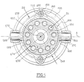
- the inner body 148 of the member 130 comprises eleven chambers 172 which are angularly distributed regularly around the shaft 150 according to a first diameter D 1 .
- a transverse rear face 176 of the internal body 148 slides over a transverse front face 178 of the bore 147 which comprises, facing each chamber 172 opening out towards the rear, lights 180 for supplying oil to the chambers 172.
- the plate 158 is controlled in inclination around axis A by at least two 182 single acting double cylinders in the axial direction, which are diametrically opposed, and which are carried by the external body 146 of the hydraulic member 130.
- the two double cylinders 182 are arranged according to a diameter D 2 which is greater than the diameter D 1 along which the pistons 174 are arranged.
- each double jack 182 has a first cylinder 184 and a second cylinder 186 coaxial concentric with the first piston 188 and the second piston Respective 190 are axially movable one relative to the other, the first piston 188 acting on the plate 158 and the second piston 190 acting on the first piston 188.
- the 182 double cylinders are arranged each on either side of the axis A of articulation of the plate 158 so as to control its inclination along the angle ⁇ .
- the two cylinders 182 are arranged in the plane P ⁇ which is perpendicular to the axis A of articulation of the plate 158, of so as to exert maximum torque around the A axis for the control in rotation of the plate around the axis A, but this provision is not limitative of the invention. Indeed, from as long as the 182 double cylinders are not aligned along the inclination axis of the plate 158, they are able to control the tilt of it.
- the value of the tilt ⁇ of the platform is determined by a control module (not shown) which controls selective feeding of 182 double cylinders, a single cylinder being supplied with pressurized oil at a time, the other being connected to an oil tank (not shown) of the transmission 10.
- the module controls the thrust of the jack 182 double located in the upper part of Figure 4 while that the double cylinder 182 located in the lower part is inactive.
- a reverse movement of articulation of the plate 158, to return it to its rest position and / or to tilt it in the opposite direction, would be obtained by controlling the thrust of the jack 182 located in the lower part of FIG. 4 while that the jack 182 located in the upper part of Figure 4 would be inactive.
- the inclination along the angle ⁇ is obtained so precise thanks to the particular design of the jack 182 which has the two cylinders 184 and 186.
- first cylinder 184 is likely to be high pressure oil supply high pressure oil of the hydraulic member 130
- second cylinder 186 is likely to be supplied with oil at the low supply pressure of the hydraulic member 130.
- the first cylinder 184 supplied with oil under high pressure, is likely to provide a significant effort which overcomes the reaction efforts of plateau 158 (which is subjected to the forces that the axial pistons 174 exert on him) by performing an approximate axial positioning of the plate 158 with respect to the required inclination ⁇ .
- the second cylinder 186 supplied with oil under low pressure, adjusts the positioning of plate 158 according to the precise value of the angle ⁇ .
- the first cylinder 184 has a first chamber 192 cylindrical rear annular, which is arranged in a bore internal 108 formed in the thickness of the external body 146, which is supplied with oil under high pressure through a lateral supply port 194, and in which slides the first tubular piston 188 whose front free end 96 cooperates with the plate 158.
- the free end 196 before the first piston 188 is shaped like a spherical head which is received in a circular groove 198 of the plate and slides in this circular groove 198 when the plate 158 is rotating, with a shoe 197 inserted.
- the throat 198 is supplied with oil under pressure by through a supply conduit 100 which passes through the free front end 196 of the piston 188 and which communication throat 198 with the first chamber 192 rear annular, so as to form, with the end 196 of the first piston 188, a hydrodynamic bearing which achieves the connection between the first cylinder 184, fixed in rotation, and the plate 158, mobile in rotation.
- the second cylinder 186 has a second chamber 102 rear cylindrical, which is coaxial to the first chamber 192 rear ring finger, and in which the second slides piston 190 whose front free end 104 cooperates with a internal rear face 106 of the first piston 188.
- the internal bore 108 of the external body 146 comprises, coaxially with the first chamber 192 rear tubular, a fixed tubular jacket 110 whose hole 112 internal radially delimits the second chamber 102 back.
- the internal hole 112 opens at the back of the shirt 110 fixed tubular to form the second supply port cylinder 186.
- the first rear tubular chamber 192 is delimited radially between the wall of the internal bore 108 of the outer body and the outer wall of the jacket 110 tubular.
- the first rear tubular chamber 192 is also delimited axially by a transverse partition rear 114 of internal bore 108.
- the internal rear face 106 of the first piston 188 of the first cylinder 186 is shaped along a portion of cone to form a support part for the front free end 104 complementary frustoconical of the second piston 190 of the second cylinder 188.
- This arrangement allows in particular the second piston 190 to bear on the first piston 188 to ensure precise positioning of the next tray the angle a while keeping a good coaxiality with respect to the first piston 188.
- the originality of the hydraulic member 130 according to the invention therefore lies particularly in its tilt tilt control using two cylinders 182 single acting doubles, which are particularly few bulky and can significantly reduce the transverse dimensions of the hydraulic member 130.
- the invention thus makes it possible to benefit from an organ 130 compact that can easily fit in a power bypass transmission housed in the engine compartment of a light passenger vehicle with a limited space devoted to the establishment of its mechanical organs.
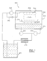
- the transmission 10 comprises means 244 for lubricating its elements, that is to say at least its input trees 212 and 220 of exit, from bridge 224 and its first epicyclic train 216 and second planetary gear train 218, which have at least one electrically driven oil pump.
- the lubrication means 244 are intended to ensure the lubrication of all rotating elements 248 of the transmission, i.e. from its 212 input trees and 220 from output, from the intermediate shaft 222 for lowering the deck 224, primary 240 and secondary 242 intermediate trees, and of its first epicyclic train 216 and second train 218 epicyclic.
- the rotating elements 248 of the transmission 10 are arranged inside a dry casing 250 of the transmission.
- the dry casing 250 is supplied, in its upper part 252 by an electric oil pump 246 supply, and it is drained, in its lower part 254, by at least one electric drain oil pump.
- the dry sump 250 is drained by two electric pumps 256 and 258.
- the oil contained in the transmission 10 is a conventionally viscous oil, for example with a viscosity index of 80W90, and the casing sec 250 has a relatively large area. He imports therefore to ensure a uniform evacuation of the oil from lubrication out of the lower 254 thereof.
- the 246 supply oil pump and oil pumps 256 and 258 are driven by a motor common electrical 259 shown in Figure 6.
- pumps 246, 256 and 258 have a common shaft 261 which is connected by a belt 263 to a shaft 265 of the engine electric 259.
- the transmission 10 includes a reservoir independent 260, separated from the dry casing 250, in which the 246 electric power pump draws oil.
- the pump 246 electrical supply includes means for limit its supply pressure, in particular a check valve discharge 262 which is intended to ensure a return of the oil in upstream of the pump when the oil pressure downstream of it is above a certain limit.
- electric feed pump delivers oil locally to the right of the rotating elements that are its input and output shafts 212, intermediate shaft 222 lowering deck 224, primary intermediate shafts 240 and secondary 242, and the first epicyclic train 216 and second epicyclic train 218.
- the input shafts 212 and output shafts 220, the intermediate shaft 222 for lowering the deck 224, the shafts primary intermediate 240 and secondary 242, and the first epicyclic train 216 and second epicyclic train 218 are each surrounded by a deflector 264, shown schematically in Figure 7, which includes means for routing oil, including lines routing 266 to the right of each of the elements turning points.
- the oil is directed only where it is necessary for the lubrication of the transmission 10.
- the deflectors 264 include means for channeling oil, in particular pipes 268 to the bottom of the dry casing 250.
- a heat exchanger 270 is interposed in the oil circuit between the oil pumps 256 and 258 drain and the oil tank 260, so as to cool the oil and allow increase the longevity of its lubricating power by limiting its degradation at high temperature.
- the transmission may also, as a variant, include additional means (not shown) for preheating lubricating oil before starting the vehicle, so as to guarantee it, from the start, adequate fluidity proper functioning of the transmission 10 and thus ensuring increased longevity to it.
- the transmission 10 therefore comprises means for effective lubrication not drawing engine power on the transmission and showing good performance.
Landscapes
- Engineering & Computer Science (AREA)
- General Engineering & Computer Science (AREA)
- Mechanical Engineering (AREA)
- General Details Of Gearings (AREA)
- Structure Of Transmissions (AREA)
Abstract
Description
- le premier planétaire et la seconde couronne sont liés à l'arbre d'entrée, les premier et second porte-satellites sont liés à l'arbre de sortie et sont susceptibles d'être liés en rotation au second arbre du convertisseur hydrostatique, la première couronne est liée au premier arbre du convertisseur hydrostatique, et le second planétaire est susceptible d'être lié en rotation au second arbre du convertisseur hydrostatique,
- les moyens mécaniques indépendants de blocage comportent un premier frein qui agit sur la première couronne et un second frein qui agit sur l'arbre de sortie du convertisseur hydrostatique,
- le premier frein est un frein à bande et en ce que le second frein est un frein à disque,
- la transmission comporte des moyens de crabotage double qui permettent de lier sélectivement en rotation le second planétaire au second arbre du convertisseur hydrostatique ou bien de lier l'arbre de sortie au second arbre du convertisseur hydrostatique,
- le convertisseur hydrostatique comporte des premier et second organes hydrauliques, qui sont associés respectivement aux premier et second arbres du convertisseur, qui sont reliés hydrauliquement l'un à l'autre, dont chacun est susceptible de fonctionner en pompe ou bien en moteur hydraulique avec une cylindrée variable commandée, pour transmettre un mouvement de rotation, de couple et de vitesse de valeurs déterminées, de l'un des premier et second organes hydrauliques à l'autre des premier et second organes hydrauliques selon des couple et vitesse de valeurs régulées,
- la transmission comporte des moyens de commande qui sont susceptibles d'établir un mode de fonctionnement dit à sortie couplée, dans lequel les moyens de crabotage double lient en rotation l'arbre de sortie au second arbre du convertisseur hydrostatique, et qui permet au moins un point de fonctionnement, dit d'adaptation, du convertisseur hydrostatique pour lequel le premier organe est à vitesse nulle pour bloquer la première couronne, et pour lequel le second organe hydraulique est à cylindrée nulle, et un mode de fonctionnement dit à deux points d'adaptation, dans lequel les moyens de crabotage double lient en rotation le second planétaire au second arbre du convertisseur hydrostatique, et qui permet au moins deux points de fonctionnement, dits d'adaptation, pour lesquels un des organes hydrauliques est à vitesse nulle pour bloquer la première couronne ou bien le second planétaire et pour lequel l'autre organe hydraulique est à cylindrée nulle,
- les moyens de commande activent le premier frein, dans le mode de fonctionnement à sortie couplée ou dans le mode de fonctionnement à deux points d'adaptation, lorsque le convertisseur hydrostatique est au point d'adaptation pour lequel le premier organe hydraulique est à vitesse nulle, et les moyens de commande activent le second frein, dans le mode de fonctionnement à deux points d'adaptation, lorsque le convertisseur hydrostatique est au point d'adaptation pour lequel le second organe hydraulique est à vitesse nulle,
- les premier et second organes hydrauliques du convertisseur hydrostatique sont des moteurs-pompes qui comportent chacun un arbre dont est solidaire un plateau inclinable de façon commandée sur lequel sont en appui des pistons axiaux, rappelés élastiquement à l'encontre du plateau, et qui coulissent dans une chambre suivant une course qui est déterminée par l'inclinaison du plateau, la variation de la course des pistons dans leurs chambre déterminant la cylindrée variable de chaque moteur-pompe.
- chaque vérin double comporte un premier et un second vérins coaxiaux concentriques dont les pistons sont mobiles l'un par rapport à l'autre avec un premier piston qui agit sur le plateau et un second piston qui agit sur le premier piston,
- le premier vérin comporte une première chambre cylindrique annulaire arrière, qui est formée dans le corps extérieur, dans laquelle coulisse le premier piston tubulaire, dont l'extrémité libre avant coopère avec le plateau,
- le second vérin comporte une seconde chambre cylindrique arrière qui est formée dans le corps extérieur, qui est coaxiale à la première chambre arrière, et dans laquelle coulisse un second piston dont l'extrémité libre avant coopère avec une face arrière interne du premier piston,
- chacune des première et seconde chambres comporte un orifice associé d'alimentation,
- le corps extérieur comporte un alésage interne dans lequel est monté, avec jeu radial, une chemise tubulaire fixe dont le trou interne délimite radialement la seconde chambre arrière, et la première chambre tubulaire arrière est délimitée radialement entre la paroi de l'alésage interne du corps extérieur et la paroi externe de la chemise tubulaire,
- une cloison transversale de l'alésage interne délimite axialement vers l'arrière la première chambre arrière,
- l'alésage interne est formé dans l'épaisseur du corps tubulaire extérieur,
- la première chambre de pression est susceptible d'être alimentée en huile à la pression haute de refoulement de l'organe hydraulique par l'intermédiaire de son orifice d'alimentation d'huile associé, et la deuxième chambre de pression est susceptible d'être alimentée en huile à la pression basse d'alimentation de l'organe hydraulique par l'intermédiaire de son orifice d'alimentation d'huile associé,
- la face arrière interne du premier piston du premier vérin est conformée suivant une tronc de cône pour former une partie d'appui pour l'extrémité libre avant tronconique complémentaire du second piston du second vérin,
- le plateau est articulé par rapport à l'arbre de l'organe hydraulique par l'intermédiaire d'une rotule,
- le plateau est de surcroít articulé en rotation par rapport à un carter fixe de l'organe hydraulique autour d'un axe perpendiculaire au plan médian commun des deux vérins doubles, notamment par l'intermédiaire de deux arbres opposés dont une extrémité de chacun est liée en rotation au carter et dont l'autre extrémité comporte des moyens de guidage d'une collerette périphérique du plateau,
- le corps extérieur de l'organe hydraulique est fixe par rapport au carter, l'extrémité libre avant du premier piston du vérin coulissant dans une gorge circulaire du plateau, et le corps intérieur de l'organe hydraulique est lié en rotation à l'arbre de l'organe hydraulique, des extrémités libres avant des pistons axiaux étant liées au plateau par des rotules,
- une tête sphérique de l'extrémité libre avant du premier piston du premier vérin est reçue de manière étanche dans une gorge circulaire du plateau qui est alimentée en huile sous pression par un conduit traversant la tête sphérique du premier piston pour former un palier hydrodynamique permettant le glissement de l'extrémité libre avant du premier piston du premier vérin dans la gorge circulaire du plateau,
- les pistons axiaux de l'organe hydraulique sont répartis autour de l'axe de l'arbre suivant un diamètre inférieur à celui selon lequel sont répartis les deux vérins doubles.
- les moyens de lubrification comportent un carter sec de la transmission qui loge au moins les arbres d'entrée et de sortie de la transmission, ses premier et second trains épicycloïdaux, et le pont ;
- le carter sec est alimenté en huile, dans sa partie supérieure, par une pompe à huile électrique d'alimentation et il est vidangé, dans sa partie inférieure, par au moins une pompe à huile électrique d'évacuation ;
- la pompe à huile électrique d'alimentation puise l'huile dans un réservoir qui est séparé du carter et la débite localement au droit des arbres d'entrée et de sortie, des premier et second trains épicycloïdaux, et du pont ;
- au moins les arbres d'entrée, de sortie, les premier et second trains épicycloïdaux, et le pont sont entourés par au moins un déflecteur qui comporte des moyens d'arrivée d'huile au droit des arbres d'entrée, de sortie, des premier et second trains épicycloïdaux, et du pont, et qui comporte de moyens pour canaliser de l'huile vers la partie inférieure du carter sec pour son évacuation ;
- la pompe à huile électrique d'évacuation vidange l'huile de la partie inférieure du carter sec pour la refouler dans le réservoir en passant à travers un échangeur thermique pour assurer son refroidissement ;
- la pompe à huile d'alimentation et la pompe à huile d'évacuation sont entraínées par un moteur électrique commun ;
- la transmission comporte des moyens pour limiter la pression d'alimentation de la pompe d'alimentation ;
- la transmission comporte des moyens de préchauffage de l'huile de lubrification avant le démarrage du véhicule.
- la figure 1 est une vue schématique d'une transmission à dérivation de puissance selon l'invention dont le premier frein est activé ; et
- la figure 2 est une vue selon la figure 1 de la transmission à dérivation de puissance selon l'invention dont le second frein est activé.
- la figure 3 est une vue en coupe axiale à plans rabattus d'un organe hydraulique selon l'invention illustrant le plateau en position de repos ;
- la figure 4 est une vue selon la figure 3 illustrant le plateau en position inclinée ;
- la figure 5 est une vue en coupe de l'organe hydraulique par la ligne 4-4 de la figure 3.
- la figure 6 met en évidence les moyens de lubrification proposées par l'invention, et
- la figure 7 est une vue schématique de ces moyens de lubrification.
Claims (33)
- Transmission (10) à dérivation de puissance, notamment pour un véhicule automobile, du type qui comporte, d'amont en aval, un arbre d'entrée (12) qui est accouplé à un moteur (14) du véhicule, un premier (16) et un second (18) trains épicycloïdaux, et un arbre (20) de sortie qui est accouplé à un pont (24) pour entraíner au moins une roue (26) du véhicule, du type dans lequel des premiers et seconds éléments des premier et second trains épicycloïdaux, notamment des premier et second planétaires (28, 34), porte-satellites (30, 36) et couronnes (32, 38) sont liés en rotation les uns aux autres, à l'arbre d'entrée (12), à l'arbre de sortie (20), à un premier arbre (40) d'un convertisseur (42) hydrostatique commandé susceptible de faire varier la raison du premier train (16) épicycloïdal, et sont liés sélectivement à un second arbre (44) du convertisseur (42) hydrostatique susceptible de faire varier la raison du second train (18) épicycloïdal par crabotage avec l'un ou l'autre de deux des seconds éléments du second train (18) épicycloïdal,
caractérisée en ce qu'elle comporte des moyens mécaniques indépendants de blocage des premier (40) et second (44) arbres du convertisseur (42) hydrostatique pour éviter les pertes d'énergie hydraulique dans ledit convertisseur (42) hydrostatique. - Transmission (10) selon la revendication précédente, caractérisée en ce que le premier planétaire (28) et la seconde couronne (38) sont liés à l'arbre d'entrée (12), les premier (30) et second (36) porte-satellites sont liés à l'arbre (20) de sortie et sont susceptibles d'être liés en rotation au second arbre (44) du convertisseur hydrostatique (42), la première couronne (32) est liée au premier arbre (40) du convertisseur hydrostatique (42), et le second planétaire (34) est susceptible d'être lié en rotation au second arbre (44) du convertisseur (42) hydrostatique.
- Transmission (10) selon la revendication précédente, caractérisée en ce que les moyens mécaniques indépendants de blocage comportent un premier frein (74) qui agit sur la première couronne (32) et un second frein (76) qui agit sur l'arbre (44) de sortie du convertisseur (42) hydrostatique.
- Transmission (10) selon la revendication précédente, caractérisée en ce que le premier frein (74) est un frein à bande et en ce que le second frein (76) est un frein à disque.
- Transmission (10) selon l'une quelconque des revendications 2 à 4, caractérisée en ce qu'elle comporte des moyens (68) de crabotage double qui permettent de lier sélectivement en rotation le second planétaire (34) au second arbre (44) du convertisseur (42) hydrostatique ou bien de lier l'arbre de sortie (20) au second arbre (44) du convertisseur (42) hydrostatique.
- Transmission (10) selon l'une quelconque des revendications précédentes, caractérisée en ce que le convertisseur (42) hydrostatique comporte des premier (70) et second (72) organes hydrauliques, qui sont associés respectivement aux premier (40) et second (44) arbres du convertisseur (42), qui sont reliés hydrauliquement l'un à l'autre, dont chacun est susceptible de fonctionner en pompe ou bien en moteur hydraulique avec une cylindrée variable commandée, pour transmettre un mouvement de rotation, de couple et de vitesse de valeurs déterminées, de l'un des premier (70) et second (72) organes hydrauliques à l'autre des premier (70) et second (72) organes hydrauliques selon des couple et vitesse de valeurs régulées.
- Transmission (10) selon la revendication précédente prise en combinaison avec la revendication 5, caractérisée en ce qu'elle comporte des moyens de commande qui sont susceptibles d'établir:un mode de fonctionnement dit à sortie couplée, dans lequel les moyens (68) de crabotage double lient en rotation l'arbre de sortie (20) au second arbre (44) du convertisseur (42) hydrostatique, et qui permet au moins un point de fonctionnement, dit d'adaptation, du convertisseur (42) hydrostatique pour lequel le premier organe (70) est à vitesse nulle pour bloquer la première couronne (32), et pour lequel le second organe (72) hydraulique est à cylindrée nulle, etun mode de fonctionnement dit à deux points d'adaptation, dans lequel les moyens (68) de crabotage double lient en rotation le second planétaire (36) au second arbre (44) du convertisseur (42) hydrostatique, et qui permet au moins deux points de fonctionnement, dits d'adaptation, pour lesquels un des organes hydrauliques (70, 72) est à vitesse nulle pour bloquer la première couronne (32) ou bien le second planétaire (34) et pour lequel l'autre organe hydraulique (70, 72) est à cylindrée nulle.
- Transmission (10), selon la revendication précédente prise en combinaison avec l'une des revendications 3 ou 4, caractérisée en ce que les moyens de commande activent le premier frein (74), dans le mode de fonctionnement à sortie couplée ou dans le mode de fonctionnement à deux points d'adaptation, lorsque le convertisseur (42) hydrostatique est au point d'adaptation pour lequel le premier organe hydraulique (70) est à vitesse nulle, et en ce que les moyens de commande activent le second frein (76), dans le mode de fonctionnement à deux points d'adaptation, lorsque le convertisseur (42) hydrostatique est au point d'adaptation pour lequel le second organe hydraulique (72) est à vitesse nulle.
- Transmission (10) selon l'une quelconque des revendications 6 à 8, caractérisée en ce que les premier (70) et second (72) organes hydrauliques du convertisseur hydrostatique (42) sont des moteurs-pompes qui comportent chacun un arbre (40, 44) dont est solidaire un plateau inclinable de façon commandée sur lequel sont en appui des pistons axiaux, rappelés élastiquement à l'encontre du plateau, et qui coulissent dans une chambre suivant une course qui est déterminée par l'inclinaison du plateau, la variation de la course des pistons dans leurs chambre déterminant la cylindrée variable de chaque moteur-pompe.
- Organe hydraulique (130, 138), notamment d'un convertisseur hydrostatique (132), susceptible de fonctionner en moteur-pompe hydraulique et comportant un arbre (150) et un plateau (158) inclinable de façon commandée avec lequel des pistons (174) axiaux sont en contact de façon à provoquer, lors de la rotation de l'arbre (150), leur coulissement dans un corps intérieur (148) de l'organe (130, 138) suivant une course qui est déterminée par l'inclinaison (α) du plateau (158), la variation de la course des pistons (174) dans leurs chambres déterminant la cylindrée variable du moteur-pompe,
caractérisé en ce que le plateau (158) de l'organe (130, 138) hydraulique est commandé en inclinaison autour d'un axe (A) perpendiculaire à la direction axiale de l'arbre (150) de l'organe (130) hydraulique par au moins deux vérins (182) doubles, à simple effet, de direction axiale, qui sont diamétralement opposés et qui sont portés par un corps extérieur (146) de l'organe hydraulique (130, 138). - Organe hydraulique (130, 138) selon la revendication précédente, caractérisé en ce que chaque vérin (182) double comporte un premier (184) et un second (186) vérins coaxiaux concentriques dont les pistons (188, 190) sont mobiles l'un par rapport à l'autre avec un premier piston (188) qui agit sur le plateau (158) et un second piston (190) qui agit sur le premier piston (188).
- Organe hydraulique (130, 138) selon la revendication précédente, caractérisé en ce que le premier vérin (184) comporte une première chambre (192) cylindrique annulaire arrière, qui est formée dans le corps (146) extérieur, dans laquelle coulisse le premier piston (188) tubulaire, dont l'extrémité (196) libre avant coopère avec le plateau (158).
- Organe hydraulique (130, 138) selon la revendication précédente, caractérisé en ce que le second vérin (186) comporte une seconde chambre (102) cylindrique arrière qui est formée dans le corps extérieur (146), qui est coaxiale à la première chambre (192) arrière, et dans laquelle coulisse un second piston (190) dont l'extrémité libre avant coopère avec une face arrière (106) interne du premier piston (188).
- Organe hydraulique (130, 138) selon la revendication précédente, caractérisé en ce que chacune des première (192) et seconde (102) chambres comporte un orifice associé (194, 112) d'alimentation.
- Organe hydraulique (130, 138) selon l'une des revendications 13 ou 14, caractérisé en ce que le corps extérieur (146) comporte un alésage interne (108) dans lequel est monté, avec jeu radial, une chemise (110) tubulaire fixe dont le trou (112) interne délimite radialement la seconde chambre (102) arrière, et en ce que la première chambre (192) tubulaire arrière est délimitée radialement entre la paroi de l'alésage (108) interne du corps extérieur et la paroi externe de la chemise (110) tubulaire.
- Organe hydraulique (130, 138) selon la revendication précédente, caractérisé en ce qu'une cloison (114) transversale de l'alésage (108) interne délimite axialement vers l'arrière la première chambre (192) arrière.
- Organe hydraulique (130, 138) selon l'une des revendications 15 ou 16, caractérisé en ce que l'alésage interne (108) est formé dans l'épaisseur du corps (146) tubulaire extérieur.
- Organe hydraulique (130, 138) selon l'une quelconque des revendications 14 à 17, caractérisé en ce que la première chambre (192) de pression est susceptible d'être alimentée en huile à la pression haute de refoulement de l'organe hydraulique (130) par l'intermédiaire de son orifice (194) d'alimentation d'huile associé, et en ce que la deuxième chambre (102) de pression est susceptible d'être alimentée en huile à la pression basse d'alimentation de l'organe hydraulique (130) par l'intermédiaire de son orifice (112) d'alimentation d'huile associé.
- Organe hydraulique (130, 138) selon l'une quelconque des revendications 13 à 18, caractérisé en ce que la face arrière (106) interne du premier piston (188) du premier vérin (184) est conformée suivant une tronc de cône pour former une partie d'appui pour l'extrémité libre avant (104) tronconique complémentaire du second piston (190) du second vérin (186).
- Organe hydraulique (130, 138) selon l'une des quelconque revendications 10 à 19, caractérisé en ce que le plateau (158) est articulé par rapport à l'arbre (150) de l'organe hydraulique par l'intermédiaire d'une rotule (160).
- Organe hydraulique (130, 138) selon la revendication précédente, caractérisé en ce que le plateau (158) est de surcroít articulé en rotation par rapport à un carter (144) fixe de l'organe hydraulique (130) autour d'un axe (A) perpendiculaire au plan médian commun des deux vérins (182) doubles, notamment par l'intermédiaire de deux arbres (168) opposés dont une extrémité de chacun est liée en rotation au carter (144) et dont l'autre extrémité comporte des moyens (197) de guidage d'une collerette (164) périphérique du plateau (158).
- Organe hydraulique (130, 138) selon l'une quelconque des revendications 10 à 21, caractérisé en ce que le corps extérieur (146) de l'organe hydraulique (130) est fixe par rapport au carter (144), l'extrémité libre (196) avant du premier piston (188) du vérin coulissant dans une gorge (198) circulaire du plateau (158), et en ce que le corps intérieur (48) de l'organe hydraulique (130) est lié en rotation à l'arbre (150) de l'organe hydraulique (130), des extrémités libres avant des pistons (174) axiaux étant liées au plateau (158) par des rotules.
- Organe hydraulique (130, 138) selon la revendication précédente, caractérisé en ce qu'une tête sphérique de l'extrémité libre (196) avant du premier piston (188) du premier vérin (184) est reçue de manière étanche dans une gorge (198) circulaire du plateau (158) qui est alimentée en huile sous pression par un conduit (100) traversant la tête sphérique du premier piston (188) pour former un palier hydrodynamique permettant le glissement de l'extrémité libre (196) avant du premier piston (184) du premier vérin dans la gorge (198) circulaire du plateau (158).
- Organe hydraulique (130, 138) selon l'une quelconque des revendications 10 à 23, caractérisé en ce que les pistons (174) axiaux de l'organe (130) hydraulique sont répartis autour de l'axe de l'arbre (150) suivant un diamètre (D1) inférieur à celui (D2) selon lequel sont répartis les deux vérins (182) doubles.
- Transmission (210) à dérivation de puissance, notamment pour un véhicule automobile, du type qui comporte, d'amont en aval, des éléments tournants (248) dont un arbre d'entrée (212) qui est accouplé à un moteur (214) du véhicule, un premier (216) et un second (218) train épicycloïdal, et un arbre (220) de sortie qui est accouplé à un pont (224) pour entraíner au moins une roue (226) du véhicule, et du type qui comporte un convertisseur (232) hydrostatique dont un premier (228) et un deuxième arbre (236) sont liés en rotation chacun à au moins un des éléments (248), caractérisée en ce qu'elle comporte des moyens (244) de lubrification, d'au moins ses arbres d'entrée (212) et de sortie (220), du pont (224) et de ses premier (216) et second (218) trains épicycloïdaux, comportant au moins une pompe (246, 256, 258) à huile à entraínement électrique.
- Transmission (10) selon la revendication précédente, caractérisée en ce que les moyens (244) de lubrification comportent un carter sec (250) de la transmission qui loge au moins les arbres (212) d'entrée et (220) de sortie de la transmission (210), ses premier (216) et second (218) trains épicycloïdaux, et le pont (224).
- Transmission (10) selon la revendication précédente, caractérisée en ce que le carter sec (250) est alimenté en huile, dans sa partie supérieure (252), par une pompe (246) à huile électrique d'alimentation et en ce qu'il est vidangé, dans sa partie inférieure (254), par au moins une pompe à huile (256, 258) électrique d'évacuation.
- Transmission (10) selon la revendication précédente, caractérisée en ce que la pompe à huile (246) électrique d'alimentation puise l'huile dans un réservoir (260) qui est séparé du carter (250) et la débite localement au droit des arbres (212) d'entrée et (220) de sortie, des premier (216) et second (218) trains épicycloïdaux, et du pont (224).
- Transmission (10) selon la revendication précédente, caractérisée en ce qu'au moins les arbres (212) d'entrée, (220) de sortie, les premier (216) et second (218) trains épicycloïdaux, et le pont (224) sont entourés par au moins un déflecteur (264) qui comporte des moyens (266) d'arrivée d'huile au droit des arbres (212) d'entrée, (220) de sortie, des premier (216) et second (218) trains épicycloïdaux, et du pont (224), et qui comporte des moyens (268) pour canaliser de l'huile vers la partie inférieure (254) du carter sec (250) pour son évacuation.
- Transmission (10) selon l'une des revendications 28 ou 29, caractérisée en que la pompe (256, 258) à huile électrique d'évacuation vidange l'huile de la partie inférieure (254) du carter sec (250) pour la refouler dans le réservoir (260) en passant à travers un échangeur (270) thermique pour assurer son refroidissement.
- Transmission (10) selon l'une quelconque des revendications 25 à 30, caractérisée en ce que la pompe à huile (246) d'alimentation et la pompe (256, 258) à huile d'évacuation sont entraínées par un moteur (259) électrique commun.
- Transmission (10) selon l'une quelconque des revendications 27 à 31, caractérisée en ce qu'elle comporte des moyens (262) pour limiter la pression d'alimentation de la pompe (246) d'alimentation.
- Transmission (10) selon l'une quelconque des revendications 25 à 32, caractérisée en ce qu'elle comporte des moyens de préchauffage de l'huile de lubrification avant le démarrage du véhicule.
Applications Claiming Priority (6)
| Application Number | Priority Date | Filing Date | Title |
|---|---|---|---|
| FR9914653A FR2801358B1 (fr) | 1999-11-22 | 1999-11-22 | Transmission a derivation de puissance comportant des moyens de blocage de ses elements |
| FR9914654A FR2801359B1 (fr) | 1999-11-22 | 1999-11-22 | Transmission a derivation de puissance comportant des moyens electriques de lubrification |
| FR9914654 | 1999-11-22 | ||
| FR9914652A FR2801348B1 (fr) | 1999-11-22 | 1999-11-22 | Organe hydraulique perfectionne |
| FR9914652 | 1999-11-22 | ||
| FR9914653 | 1999-11-22 |
Publications (2)
| Publication Number | Publication Date |
|---|---|
| EP1101977A2 true EP1101977A2 (fr) | 2001-05-23 |
| EP1101977A3 EP1101977A3 (fr) | 2006-09-13 |
Family
ID=27253563
Family Applications (1)
| Application Number | Title | Priority Date | Filing Date |
|---|---|---|---|
| EP00403209A Withdrawn EP1101977A3 (fr) | 1999-11-22 | 2000-11-17 | Transmission à dérivation de puissance |
Country Status (1)
| Country | Link |
|---|---|
| EP (1) | EP1101977A3 (fr) |
Cited By (2)
| Publication number | Priority date | Publication date | Assignee | Title |
|---|---|---|---|---|
| EP1342937A3 (fr) * | 2002-03-06 | 2008-03-19 | CNH Belgium N.V. | Transmission continue de vitesse |
| DE102010003945A1 (de) * | 2009-07-15 | 2011-01-20 | Zf Friedrichshafen Ag | Getriebevorrichtung für ein Fahrzeug mit einem Gehäuse und mit wenigstens einem Variator |
Citations (1)
| Publication number | Priority date | Publication date | Assignee | Title |
|---|---|---|---|---|
| FR2520827A1 (fr) | 1982-02-03 | 1983-08-05 | Moteur Moderne Le | Transmission a division de puissance concue pour fonctionner en traction pure, en recuperation-restitution de l'energie cinetique, et en mode hybride |
Family Cites Families (14)
| Publication number | Priority date | Publication date | Assignee | Title |
|---|---|---|---|---|
| US2356101A (en) * | 1942-10-09 | 1944-08-15 | Cash A W Co | Multiple cylinder pump |
| US3810715A (en) * | 1972-08-07 | 1974-05-14 | Gen Motors Corp | Hydrostatic machine valve biasing system |
| JPS5623069B2 (fr) * | 1974-02-06 | 1981-05-28 | ||
| US4028010A (en) * | 1974-06-21 | 1977-06-07 | Caterpillar Tractor Co. | Reversible, variable-displacement piston pump with positioner means for automatic return to zero displacement |
| JPS5977086A (ja) * | 1982-10-22 | 1984-05-02 | Mitsubishi Heavy Ind Ltd | 斜板形アキシヤルピストンポンプ、モ−タ |
| FR2538042B1 (fr) * | 1982-12-21 | 1987-12-18 | Linde Ag | Installation de reglage hydraulique pour une machine hydrostatique |
| EP0564003A1 (fr) * | 1987-05-12 | 1993-10-06 | Jarchow, Friedrich, Prof. Dr.-Ing. | Boîte de vitesse hydrostatique-mécanique à réglage continu |
| IT1248936B (it) * | 1990-06-04 | 1995-02-11 | Fritz Carl Anton Hurth | Gruppo riduttore-riparatore per gruppi cambio particolarmente per macchine industriali |
| IT1254653B (it) * | 1992-03-02 | 1995-09-28 | Struttura di gruppo a diramazione di potenza particolarmente per macchine agricole, industriali e simili | |
| NL1001279C2 (nl) * | 1995-09-25 | 1997-03-26 | Doornes Transmissie Bv | Continu variabele transmissie. |
| DE19615929A1 (de) * | 1996-04-22 | 1997-10-23 | Zahnradfabrik Friedrichshafen | Getriebeschmierung |
| JP3861340B2 (ja) * | 1996-09-11 | 2006-12-20 | アイシン・エィ・ダブリュ株式会社 | 車両用動力伝達装置の電動オイルポンプ制御装置 |
| SE507454C2 (sv) * | 1997-04-16 | 1998-06-08 | Ove Hammarstrand | Kraftöverförande system |
| DE19807443A1 (de) * | 1998-02-24 | 1999-08-26 | Kleinedler | Axialkolbenmaschine |
-
2000
- 2000-11-17 EP EP00403209A patent/EP1101977A3/fr not_active Withdrawn
Patent Citations (1)
| Publication number | Priority date | Publication date | Assignee | Title |
|---|---|---|---|---|
| FR2520827A1 (fr) | 1982-02-03 | 1983-08-05 | Moteur Moderne Le | Transmission a division de puissance concue pour fonctionner en traction pure, en recuperation-restitution de l'energie cinetique, et en mode hybride |
Cited By (2)
| Publication number | Priority date | Publication date | Assignee | Title |
|---|---|---|---|---|
| EP1342937A3 (fr) * | 2002-03-06 | 2008-03-19 | CNH Belgium N.V. | Transmission continue de vitesse |
| DE102010003945A1 (de) * | 2009-07-15 | 2011-01-20 | Zf Friedrichshafen Ag | Getriebevorrichtung für ein Fahrzeug mit einem Gehäuse und mit wenigstens einem Variator |
Also Published As
| Publication number | Publication date |
|---|---|
| EP1101977A3 (fr) | 2006-09-13 |
Similar Documents
| Publication | Publication Date | Title |
|---|---|---|
| EP1442238B1 (fr) | Installation de lubrification pour boite de transmission de puissance basculante | |
| FR2678342A1 (fr) | Convertisseur de couple de rotation hydrodynamique. | |
| EP1750967B1 (fr) | Element de transmission a embrayages humides pour chaine de traction hybride de vehicule automobile, et vehicule automobile equipe d'un tel element | |
| FR2771468A1 (fr) | Boite de vitesse reglable en continu pour vehicule automobile | |
| FR2732746A1 (fr) | Systeme d'alimentation en huile pour la commande de composants de vehicule de travail | |
| FR2731487A1 (fr) | Convertisseur de couple hydrodynamique avec accouplement de pompe et de pontage | |
| EP0708894B1 (fr) | Dispositif d'accouplement volumetrique | |
| FR2798983A1 (fr) | Dispositif de lubrification d'un ensemble mecanique multiplicateur-reducteur | |
| FR2596480A1 (fr) | Transmission a vitesse variable | |
| FR2830902A1 (fr) | Appareil moteur-generateur a vitesse variable destine a etre utilise avec un moteur a combustion | |
| FR2493938A1 (fr) | Perfectionnements aux convertisseurs de couples hydrauliques | |
| EP3081817A1 (fr) | Machine équipée d'un compresseur ou d'une pompe | |
| FR2799255A1 (fr) | Boite de vitesses ,notamment boite de vitesses automatique a dispositif de regulation du flux volumique. | |
| FR2792051A1 (fr) | Installation de couplage hydrodynamique notamment convertisseur de couple | |
| FR2634265A1 (fr) | Transmission pour l'entrainement d'une machine a une vitesse de rotation variable | |
| FR2901325A1 (fr) | Pompe a engrenages interieurs | |
| FR2497736A1 (fr) | Systeme d'entrainement a quatre roues motrices pour un vehicule a roues | |
| EP0428192B1 (fr) | Variateur hydrostatique de vitesse à pistons radiaux | |
| FR2832197A1 (fr) | Dispositif d'embrayage notamment pour vehicules automobiles | |
| EP1186802A1 (fr) | Dispositif d'entraínement comprenant un moteur hydraulique et un réducteur | |
| FR2697883A1 (fr) | Ensemble hydromécanique d'entraînement. | |
| FR2553487A1 (fr) | Dispositif de commande d'accouplement direct destine a un engrenage hydraulique pour une transmission automatique d'automobile | |
| EP4127417B1 (fr) | Ensemble pour turbomachine d'aéronef comportant un système amelioré de lubrification d'un réducteur d'entrainement de soufflante | |
| EP1055844A1 (fr) | Transmission hydromécanique continue à dérivation de puissance pour véhicule automobile | |
| FR2646380A1 (fr) | Dispositif formant groupe moto-propulseur notamment pour vehicule automobile |
Legal Events
| Date | Code | Title | Description |
|---|---|---|---|
| PUAI | Public reference made under article 153(3) epc to a published international application that has entered the european phase |
Free format text: ORIGINAL CODE: 0009012 |
|
| AK | Designated contracting states |
Kind code of ref document: A2 Designated state(s): AT BE CH CY DE DK ES FI FR GB GR IE IT LI LU MC NL PT SE TR |
|
| AX | Request for extension of the european patent |
Free format text: AL;LT;LV;MK;RO;SI |
|
| RAP1 | Party data changed (applicant data changed or rights of an application transferred) |
Owner name: RENAULT S.A.S. |
|
| PUAL | Search report despatched |
Free format text: ORIGINAL CODE: 0009013 |
|
| AK | Designated contracting states |
Kind code of ref document: A3 Designated state(s): AT BE CH CY DE DK ES FI FR GB GR IE IT LI LU MC NL PT SE TR |
|
| AX | Request for extension of the european patent |
Extension state: AL LT LV MK RO SI |
|
| AKX | Designation fees paid | ||
| REG | Reference to a national code |
Ref country code: DE Ref legal event code: 8566 |
|
| STAA | Information on the status of an ep patent application or granted ep patent |
Free format text: STATUS: THE APPLICATION IS DEEMED TO BE WITHDRAWN |
|
| 18D | Application deemed to be withdrawn |
Effective date: 20070314 |