EP1101666A2 - Dreipunkt-Sicherheitsgurtsystem - Google Patents
Dreipunkt-Sicherheitsgurtsystem Download PDFInfo
- Publication number
- EP1101666A2 EP1101666A2 EP01103450A EP01103450A EP1101666A2 EP 1101666 A2 EP1101666 A2 EP 1101666A2 EP 01103450 A EP01103450 A EP 01103450A EP 01103450 A EP01103450 A EP 01103450A EP 1101666 A2 EP1101666 A2 EP 1101666A2
- Authority
- EP
- European Patent Office
- Prior art keywords
- seat belt
- deflection
- belt system
- point seat
- rollers
- Prior art date
- Legal status (The legal status is an assumption and is not a legal conclusion. Google has not performed a legal analysis and makes no representation as to the accuracy of the status listed.)
- Withdrawn
Links
- 239000002184 metal Substances 0.000 description 5
- 238000004519 manufacturing process Methods 0.000 description 3
- 238000005096 rolling process Methods 0.000 description 3
- 238000004804 winding Methods 0.000 description 3
- 206010063493 Premature ageing Diseases 0.000 description 1
- 208000032038 Premature aging Diseases 0.000 description 1
- 238000004873 anchoring Methods 0.000 description 1
- 238000005452 bending Methods 0.000 description 1
- 230000006378 damage Effects 0.000 description 1
- 230000006735 deficit Effects 0.000 description 1
- 238000005516 engineering process Methods 0.000 description 1
- 239000000463 material Substances 0.000 description 1
- 238000007790 scraping Methods 0.000 description 1
Images


Classifications
-
- B—PERFORMING OPERATIONS; TRANSPORTING
- B60—VEHICLES IN GENERAL
- B60R—VEHICLES, VEHICLE FITTINGS, OR VEHICLE PARTS, NOT OTHERWISE PROVIDED FOR
- B60R22/00—Safety belts or body harnesses in vehicles
- B60R22/18—Anchoring devices
- B60R22/24—Anchoring devices secured to the side, door, or roof of the vehicle
-
- B—PERFORMING OPERATIONS; TRANSPORTING
- B60—VEHICLES IN GENERAL
- B60R—VEHICLES, VEHICLE FITTINGS, OR VEHICLE PARTS, NOT OTHERWISE PROVIDED FOR
- B60R22/00—Safety belts or body harnesses in vehicles
- B60R22/18—Anchoring devices
- B60R2022/1818—Belt guides
- B60R2022/1825—Belt guides using rollers
Definitions
- the present invention relates to a three-point seat belt system, especially for motor vehicle seats, with a seat belt that can be unwound from a reel via a deflection device arranged laterally above the seat is guided, which is a passage opening has, the lower limit by a pulley for the seat belt is formed.
- the three-point seat belt systems common in motor vehicles have a role from which the seat belt can be developed. This role is particularly at Seat belts for the front seats of a passenger car to the side of the associated seat in the floor area on the so-called B-pillar struck. Based on this role the belt is on the side above the seat on the B-pillar arranged deflection device and from there again back to a second mounting bracket for led the far end of the belt. Between the deflection device and the second floor mounting bracket is the seat belt through the implementation of a locking element led, which with one on the other the associated seat arranged buckle interacts.
- the invention has for its object a three-point seat belt system of the type mentioned at the beginning, that the removal of the webbing facilitates and prevents impairment or destruction of the same becomes.
- the deflection device has at least one further role.
- another role can be at least one essentially perpendicular to the deflection roller Guide roller can be provided which the passage opening limited laterally.
- the leadership role is that of a lateral Limitation of the passage opening of the deflection device Wandering belt not rubbed against this side boundary becomes. Instead, the webbing sets the existing one additional leadership role in motion, creating a distinct Reduction of trigger resistance and wear of the webbing is reached. To both when unwinding the wear on both sides also when winding To reduce edge areas of the webbing are preferred two additional guide rollers are provided, which the Passage opening of the deflection device on both sides of the Limit deflection roller.
- the Jacket of the lateral guide rollers directly on the Cover the pulley. This ensures that the respective lateral guide role from that to this Side belt is immediately rotated. It also prevents the belt from being pulled into a gap becomes.
- the lateral surface of the side rollers is preferred in each case concave. This ensures in a particularly advantageous manner Way that the belt bumpless and kink-free side roll runs up.
- the object on which the invention is based becomes another solved in that the lower limit of the passage opening is formed by a deflecting surface, and that a Part of the deflection surface through the jacket at least one Deflection roller is formed.
- a deflection surface with at least one used pulley a proportionate allows easy removal of the webbing.
- the deflection surface is in the direction of passage of the webbing is gently curved and the pulleys one smaller than the radius of curvature of the deflecting surface Have radius of curvature.
- the gently curved deflection surface prevents the webbing from bending too much the deflection device, which would make it difficult to pull off.
- a smooth running of the pulleys ensures that also makes it easier to pull off the webbing becomes.
- the guide rollers are arranged distributed over the deflection surface, wherein preferably a total of two or three to one another essentially parallel pulleys are provided.
- the usage of two or three pulleys has proven to be particularly advantageous emphasized because the two or three roles, in particular if arranged over the deflection surface are, on the one hand, very little friction when pulling through ensure the webbing and on the other hand only a small one Rolling resistance is given.
- the design Cost-effective with two or three roles are possible.
- the deflection rollers and / or the lateral rollers are preferred stored in a plastic part, which is jacket-like can be placed on a preferably made of metal bracket part is. This also simplifies and reduces the cost of production, since the storage means for all roles in the plastic part can be trained.
- This is preferably made of metal or also a bracket part made of another stable material ensures a sufficiently firm anchoring the seat belt in the case of a heavy load, such as it occurs in an accident.
- the bearings for the deflection rollers and the side guide rollers by at least one cover part that can preferably be clipped on coverable.
- This configuration simplifies the assembly of the arrangement according to the invention, since the roles simply in Plastic part can be used and then only the cover must still be clipped on.
- the outer surfaces of the pulleys and / or the lateral According to a further embodiment of the Invention be smooth. According to another embodiment the invention, it is also possible, the lateral surfaces structured to train the movement of the Webbing to the lateral boundaries of the passage opening to influence in the deflection device.
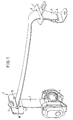
- Fig. 1 shows the essential parts of the invention Three-point seat belt system, namely a reel 1, from which the seat belt 2 can be unwound, an upper one Deflection device 3 with a passage opening 4, through which the seat belt 2 is guided, a lower fastening fitting 5 for the end 6 of the seat belt remote from the roll 2 and a locking element 7 with an implementation 8 for the seat belt 2, which is between the upper Deflection device 3 and lower mounting bracket 5 is provided is.
- the locking element 7 does not work with one here Belt buckle shown on the roller 1 facing away Side of the associated vehicle seat, which also here is not shown together.
- the upper deflection device 3 has a deflection roller 9, which the passage opening 4 of the deflection device 3 after limited below.
- the deflection device 3 has two lateral rollers 10, which defines the passage opening 4 of the deflection device 3 limit laterally.
- the bottom of the deflection device 3 The seat belt is fed in and pulled off diagonally downwards and forwards 2 is largely free of friction in this way through the passage opening 4 of the deflection device 3 guided.
- the seat belt moves when unwinding or rolling up one side of the passage opening 4 of the deflection device 3 there, he runs onto one of the concave surfaces lateral rollers 10 so that it also laterally largely smoothly through the passage opening 4 of the Deflection device 3 is performed. Because of the concave Shell surface of the side rollers 10, which is also flush connect the jacket of the pulley 9 is also ensures that the seat belt 2 is free of bumps and kinks runs onto the side rollers 10. The burden of Belt strap is thereby greatly reduced, so that the Loading of the lateral edge areas of the webbing and the associated risk of tearing accordingly is reduced.
- the configuration of the deflection device 3 in represented individual.
- the housing 13 consists of a coatable part 14 which can be applied to the bow part 11, in which the bearings 15 and 16 for the pulley 9 and the lateral guide rollers 10 are formed.
- the second Housing part is designed as a clip-on cover part 17, which the bearings 15 and 16 of the pulley 9 and the side Guide rollers 10 covers towards the front.
- the guide roller 9 and the side Guide rollers 10 simply from the front into the associated bearings 15 and 16 can be used and are made easy by that clip part 17 held securely.
- Through this Design is both manufacture and assembly the deflection device 3 simplified.
- the one to be picked up by the deflection device 3 in the event of an accident Force is preferably formed by the metal Bracket part 11 derived from the motor vehicle.
- the deflection device 3 each consists of a plastic-coated, metal bracket 21, which has a passage opening 22 for the webbing 2 has.
- the lower limit of the passage opening 22 is in each case by a gently in the direction of passage of the webbing 2 curved deflection surface 18 formed in the deflection rollers 20th are used in such a way that the jackets 19 of the deflection rollers 20 each form part of the deflection surface 18.
- the between the coats 19 of the guide rollers 20 remaining part the deflection surface 18 is assigned by the lower one Cross strut 23 of the bracket 21 is formed.
- FIGS. 3 and 4 there are three mutually parallel deflection rollers 20 are provided, of which one each at the belt-side and outlet-side end of the Deflection surface 18 is arranged while the third deflection roller 20 is provided in the middle of the deflection surface 18, So with her jacket 19 the apex of the curved Deflection surface 18 forms.
- the radii of curvature are that in the Bracket 21 mounted pulleys 20 relative to the radius of curvature the deflection surface 18 smaller, so that the rolling resistance the deflection rollers 20 is also small.
- the distributed arrangement of the two or three pulleys 20 over the deflecting surface 18 becomes a low withdrawal resistance of the Webbing 2 reached.
- more than three or even a single pulley with a small one Radius of curvature may be provided.
- only one Deflection roller is preferably located in the middle of the Deflection surface 18, thus forms its apex.
- the inventive Seat belt system the pull resistance of the webbing 2 kept low and the wear of the webbing 2 clearly reduced. Due to the lateral guide rollers 10 Risk of lateral tearing of the webbing 2 reduced which in known webbing by scraping the Webbing occurs on the fixed edges.
Landscapes
- Engineering & Computer Science (AREA)
- Mechanical Engineering (AREA)
- Automotive Seat Belt Assembly (AREA)
Abstract
Description
- Fig. 1
- eine perspektivische Darstellung des erfindungsgemäßen Sicherheitsgurtsystems,
- Fig. 2
- ein Detail von Fig. 1 in vergrößerter Explosionsdarstellung,
- Fig. 3
- eine Draufsicht auf die Umlenkeinrichtung einer Variante des erfindungsgemäßen Sicherheitsgurtsystems,
- Fig. 4
- einen Querschnitt durch die Umlenkeinrichtung von Fig. 3, und
- Fig. 5
- eine perspektivische Darstellung der Umlenkeinrichtung einer weiteren Variante des erfindungsgemäßen Sicherheitsgurtsystems.
Claims (8)
- Dreipunkt-Sicherheitsgurtsystem, insbesondere für Kraftfahrzeugsitze, mit einem von einer Rolle (1) abwickelbaren Sicherheitsgurt (2), der über eine seitlich oberhalb des Sitzes angeordnete Umlenkeinrichtung (3) geführt ist, welche eine Durchtrittsöffnung (4) für den Sicherheitsgurt (2) aufweist,
dadurch gekennzeichnet,
daß die untere Begrenzung der Durchtrittsöffnung (4) durch eine Umlenkfläche (18) gebildet wird, und daß ein Teil der Umlenkfläche (18) durch den Mantel (19) mindestens einer Umlenkrolle (20) gebildet wird. - Dreipunkt-Sicherheitsgurtsystem nach Anspruch 1,
dadurch gekennzeichnet,
daß die Umlenkfläche (18) in Durchtrittsrichtung des Gurtbandes (2) sanft gekrümmt ist. - Dreipunkt-Sicherheitsgurtsystem nach Anspruch 2,
dadurch gekennzeichnet,
daß die Umlenkrollen (20) einen im Verhältnis zum Krümmungsradius der Umlenkfläche (18) kleineren Krümmungsradius aufweisen. - Dreipunkt-Sicherheitsgurtsystem nach Anspruch 3,
dadurch gekennzeichnet,
daß die Umlenkrollen (20) über die Umlenkfläche (18) verteilt angeordnet sind. - Dreipunkt-Sicherheitsgurtsystem nach einem der Ansprüche 1 bis 3,
dadurch gekennzeichnet,
daß insgesamt zwei oder drei zueinander im wesentlichen parallele Umlenkrollen (20) vorgesehen sind. - Dreipunkt-Sicherheitsgurtsystem nach einem der vorhergehenden Ansprüche,
dadurch gekennzeichnet,
daß zur Lagerung der Umlenkrollen jeweils Gleitlager vorgesehen sind. - Dreipunkt-Sicherheitsgurtsystem nach einem der vorhergehenden Ansprüche,
dadurch gekennzeichnet,
daß die Mantelflächen der Umlenkrollen (20) glatt ausgebildet sind. - Dreipunkt-Sicherheitsgurtsystem nach einem der Ansprüche 1 bis 6,
dadurch gekennzeichnet,
daß die Mantelflächen der Umlenkrollen (20) strukturiert sind.
Applications Claiming Priority (5)
| Application Number | Priority Date | Filing Date | Title |
|---|---|---|---|
| DE19615625 | 1996-04-19 | ||
| DE19615625 | 1996-04-19 | ||
| DE19626800 | 1996-07-03 | ||
| DE19626800A DE19626800A1 (de) | 1996-04-19 | 1996-07-03 | Dreipunkt-Sicherheitsgurtsystem mit Rollenumlenkbeschlag |
| EP97106591A EP0802097B1 (de) | 1996-04-19 | 1997-04-21 | Dreipunkt-Sicherheitsgurtsystem |
Related Parent Applications (2)
| Application Number | Title | Priority Date | Filing Date |
|---|---|---|---|
| EP97106591.7 Division | 1997-04-21 | ||
| EP97106591A Division EP0802097B1 (de) | 1996-04-19 | 1997-04-21 | Dreipunkt-Sicherheitsgurtsystem |
Publications (2)
| Publication Number | Publication Date |
|---|---|
| EP1101666A2 true EP1101666A2 (de) | 2001-05-23 |
| EP1101666A3 EP1101666A3 (de) | 2001-09-19 |
Family
ID=7791841
Family Applications (1)
| Application Number | Title | Priority Date | Filing Date |
|---|---|---|---|
| EP01103450A Withdrawn EP1101666A3 (de) | 1996-04-19 | 1997-04-21 | Dreipunkt-Sicherheitsgurtsystem |
Country Status (2)
| Country | Link |
|---|---|
| EP (1) | EP1101666A3 (de) |
| DE (2) | DE19626800A1 (de) |
Family Cites Families (3)
| Publication number | Priority date | Publication date | Assignee | Title |
|---|---|---|---|---|
| DE2943441A1 (de) * | 1979-10-26 | 1981-04-30 | Repa Feinstanzwerk Gmbh, 7071 Alfdorf | Gurtband-bremsvorrichtung fuer sicherheitsgurtsysteme |
| DE3041103C2 (de) * | 1980-10-31 | 1984-05-10 | Repa Feinstanzwerk Gmbh, 7071 Alfdorf | Sicherheitsgurtanordnung |
| DE3144527A1 (de) * | 1981-11-10 | 1983-05-19 | Klippan GmbH, Sicherheitsgeräte, 2000 Norderstedt | Vorrichtung zur fuehrung oder umlenkung eines bandes, insbesondere fuer einen sicherheitsgurt in einem kraftfahrzeug |
-
1996
- 1996-07-03 DE DE19626800A patent/DE19626800A1/de not_active Withdrawn
-
1997
- 1997-04-21 DE DE59704745T patent/DE59704745D1/de not_active Expired - Fee Related
- 1997-04-21 EP EP01103450A patent/EP1101666A3/de not_active Withdrawn
Non-Patent Citations (1)
| Title |
|---|
| None |
Also Published As
| Publication number | Publication date |
|---|---|
| DE19626800A1 (de) | 1997-10-23 |
| EP1101666A3 (de) | 2001-09-19 |
| DE59704745D1 (de) | 2001-11-08 |
Similar Documents
| Publication | Publication Date | Title |
|---|---|---|
| DE3330938A1 (de) | Einziehvorrichtung fuer sicherheitsgurte mit integrierter gurtsperre und programmklinke | |
| DE4339114C2 (de) | Sitzkissen eines Kraftwagensitzes | |
| DE3218214A1 (de) | Gleitschienenfuehrung fuer fahrzeugsitze | |
| DE3023093C2 (de) | Umlenkbeschlag für einen Sicherheitsgurt | |
| EP0802097B1 (de) | Dreipunkt-Sicherheitsgurtsystem | |
| DE2817741A1 (de) | Umlenkbeschlag fuer sicherheitsgurte, insbesondere fuer kraftfahrzeuge | |
| DE19913423C1 (de) | Umlenkeinrichtung für einen Sicherheitsgurt | |
| EP0941899A1 (de) | Sicherheitsgurtanordnung | |
| DE3112458C2 (de) | Stufenweise höhenverstellbare Sicherheitsgurtumlenkung in Fahrzeugen, insbesondere Kraftfahrzeugen | |
| EP0257604B1 (de) | Umlenkklemmer | |
| DE3041103C2 (de) | Sicherheitsgurtanordnung | |
| EP0941898A1 (de) | Umlenkbeschlag für einen Sicherheitsgurt | |
| DE10210781B4 (de) | Befestigungsmittel für einen Sicherheitsgurt | |
| DE2711401A1 (de) | Sicherheitsgurtanordnung fuer fahrzeuge, insbesondere kraftfahrzeuge | |
| EP1101666A2 (de) | Dreipunkt-Sicherheitsgurtsystem | |
| EP0952048A1 (de) | Gurtaufroller für ein Sicherheitsgurt-Rückhaltesystem | |
| DE2541647A1 (de) | Sicherheitsgurtanordnung, insbesondere fuer kraftfahrzeuge | |
| DE8611961U1 (de) | Umlenkbeschlag | |
| DE3209351A1 (de) | Fahrzeug mit einem in einer laengsfuehrung gefuehrten sitz und mit sitzbefestigtem sicherheitsgurt | |
| DE2920810C2 (de) | Sicherheitsgurtsystem für ein Kraftfahrzeug | |
| DE2912248A1 (de) | Sicherheitsgurtsystem fuer fahrzeuge | |
| DE2734995C3 (de) | Sitzgurt-Aufrolleinrichtung | |
| DE2608046A1 (de) | Sicherheitsgurtanordnung mit gurtaufrollvorrichtung fuer fahrzeuge, insbesondere kraftfahrzeuge | |
| DE2614472B1 (de) | Gurtaufroller fuer Sicherheitsgurte | |
| DE3425526C2 (de) |
Legal Events
| Date | Code | Title | Description |
|---|---|---|---|
| PUAI | Public reference made under article 153(3) epc to a published international application that has entered the european phase |
Free format text: ORIGINAL CODE: 0009012 |
|
| AC | Divisional application: reference to earlier application |
Ref document number: 802097 Country of ref document: EP |
|
| AK | Designated contracting states |
Kind code of ref document: A2 Designated state(s): DE GB |
|
| PUAL | Search report despatched |
Free format text: ORIGINAL CODE: 0009013 |
|
| RIN1 | Information on inventor provided before grant (corrected) |
Inventor name: DREIZLER, SABINE Inventor name: PLEYER, MATTHIAS Inventor name: KOPETZKY, ROBERT |
|
| AK | Designated contracting states |
Kind code of ref document: A3 Designated state(s): DE GB |
|
| 17P | Request for examination filed |
Effective date: 20011227 |
|
| AKX | Designation fees paid |
Free format text: DE GB |
|
| RAP1 | Party data changed (applicant data changed or rights of an application transferred) |
Owner name: TAKATA-PETRI (ULM) GMBH |
|
| 17Q | First examination report despatched |
Effective date: 20030515 |
|
| STAA | Information on the status of an ep patent application or granted ep patent |
Free format text: STATUS: THE APPLICATION IS DEEMED TO BE WITHDRAWN |
|
| 18D | Application deemed to be withdrawn |
Effective date: 20031126 |