EP1097635A2 - Dispositif d'équilibrage de pression de liquide et procédé pour changer la proportion d'équilibrage de pression - Google Patents
Dispositif d'équilibrage de pression de liquide et procédé pour changer la proportion d'équilibrage de pression Download PDFInfo
- Publication number
- EP1097635A2 EP1097635A2 EP00122826A EP00122826A EP1097635A2 EP 1097635 A2 EP1097635 A2 EP 1097635A2 EP 00122826 A EP00122826 A EP 00122826A EP 00122826 A EP00122826 A EP 00122826A EP 1097635 A2 EP1097635 A2 EP 1097635A2
- Authority
- EP
- European Patent Office
- Prior art keywords
- valve
- valve pin
- sleeve
- housing
- insert
- Prior art date
- Legal status (The legal status is an assumption and is not a legal conclusion. Google has not performed a legal analysis and makes no representation as to the accuracy of the status listed.)
- Granted
Links
- 239000007788 liquid Substances 0.000 title claims abstract description 29
- 238000000034 method Methods 0.000 title claims description 10
- 238000007789 sealing Methods 0.000 claims abstract description 17
- 241001465754 Metazoa Species 0.000 claims abstract description 9
- 238000005192 partition Methods 0.000 claims description 17
- 210000002105 tongue Anatomy 0.000 claims description 10
- 230000005489 elastic deformation Effects 0.000 claims description 4
- 239000007769 metal material Substances 0.000 claims description 2
- 229910001220 stainless steel Inorganic materials 0.000 claims description 2
- 239000010935 stainless steel Substances 0.000 claims description 2
- XLYOFNOQVPJJNP-UHFFFAOYSA-N water Substances O XLYOFNOQVPJJNP-UHFFFAOYSA-N 0.000 abstract description 71
- 230000035622 drinking Effects 0.000 abstract description 16
- 238000003780 insertion Methods 0.000 description 20
- 230000037431 insertion Effects 0.000 description 20
- 210000002445 nipple Anatomy 0.000 description 3
- 229920003023 plastic Polymers 0.000 description 3
- 244000144977 poultry Species 0.000 description 2
- 230000007704 transition Effects 0.000 description 2
- 239000000654 additive Substances 0.000 description 1
- 230000015572 biosynthetic process Effects 0.000 description 1
- 239000003638 chemical reducing agent Substances 0.000 description 1
- 238000004140 cleaning Methods 0.000 description 1
- 239000003651 drinking water Substances 0.000 description 1
- 235000020188 drinking water Nutrition 0.000 description 1
- 229940079593 drug Drugs 0.000 description 1
- 239000003814 drug Substances 0.000 description 1
- 210000003746 feather Anatomy 0.000 description 1
- 238000011010 flushing procedure Methods 0.000 description 1
- 238000005755 formation reaction Methods 0.000 description 1
- 230000005484 gravity Effects 0.000 description 1
- 239000000463 material Substances 0.000 description 1
- 238000000465 moulding Methods 0.000 description 1
- 230000002093 peripheral effect Effects 0.000 description 1
- 238000000926 separation method Methods 0.000 description 1
- 238000013022 venting Methods 0.000 description 1
- 230000000007 visual effect Effects 0.000 description 1
Images
Classifications
-
- A—HUMAN NECESSITIES
- A01—AGRICULTURE; FORESTRY; ANIMAL HUSBANDRY; HUNTING; TRAPPING; FISHING
- A01K—ANIMAL HUSBANDRY; AVICULTURE; APICULTURE; PISCICULTURE; FISHING; REARING OR BREEDING ANIMALS, NOT OTHERWISE PROVIDED FOR; NEW BREEDS OF ANIMALS
- A01K39/00—Feeding or drinking appliances for poultry or other birds
- A01K39/02—Drinking appliances
- A01K39/0213—Nipple drinkers
Definitions
- the invention relates to a device for balancing the Pressure of a liquid, especially one preferably inclined liquid line for feeding drinking nipples for animals according to the preamble of claim 1. Furthermore The invention relates to a method for changing the Pressure balance ratio in particular an inclined Liquid line for feeding drinking nipples for animals according to the preamble of claim 10.
- Devices of the type mentioned here are in technical jargon referred to as a gradient controller. They are preferably used in the course of inclined liquid lines for feeding Drinking nipples for animals, especially poultry. With inclined Liquid lines the pressure increases in the course of the same.
- the gradient controls are used to control the pressure over the course of the inclined liquid line to even out.
- the object of the invention is a device (gradient controller) and a method of the beginning to create the type mentioned, making it easier and more reliable Way the pressure along the sloping liquid lines Is adaptable accordingly.
- valve assembly preferably has cylindrical valve pin which can be through Dead weight closes, can with the well-known incline or the spring pressure regulator required. Moreover the valve pin ensures reliable opening and Close the valve assembly because it is preferred by its cylindrical shape move up and down safely leaves.
- valve arrangement of a chamber for allocate draining liquid This allows the valve pin vertically above the chamber of the inflowing liquid to be ordered. Because of this, the movable up and down Valve pin due to its own weight the valve arrangement conclude.
- Valve pin preferably on its underside with a conical, in particular frustoconical, sealing surface.
- This frustoconical sealing surface corresponds to a likewise conical, in particular frustoconical Valve seat.
- the guide for the valve pin longer than the length of the same.
- the guide has a 1.5 to 2 times the length of the Valve pin. This can be used to flush the liquid line the valve pin so far from the valve seat in preferably a partition between the chambers that move away Sufficiently large liquid flow for flushing the liquid line can also flow through the valve assembly.
- the Incline controller according to the invention thereby leaves an unhindered Rinse the drinking device.
- the guide for the valve pin is provided in to provide a sleeve-like insertion part, which in a corresponding socket or sleeve of the housing arranged is. It can be so with the plug-in part of the valve pin Valve arrangement from the socket arranged on the housing or Take out the gradient regulator sleeve, for example to Clean the valve assembly.
- the Valve pin To the insert part together with to be able to assemble and disassemble the valve pin is the Valve pin in the plug-in part secured against falling out.
- the insertion part preferably has spring tongues which, due to an elastic deformation, separates the Allow valve pin from plug-in part if the valve pin to be replaced.
- valve assembly with valve bodies of different weight provided to the pressure compensation ratio of the gradient controller to change.
- the slope regulator With a comparatively heavy valve body the slope regulator carries a larger pressure difference between the liquid flowing into the chamber and the chamber of the flowing liquid.
- an easier one Valve body to lower pressure difference in through the Valve arrangement connected chambers that way is one simple and inexpensive change of the gradient controller achievable pressure conditions possible.
- valve body is co-located with the plug-in part replaced.
- the extractable in the housing of the Slope part arranged in the incline is easy to use assemble and disassemble. Removing the valve body from the Insert part can then be superfluous, so that inside it is possible to retrofit the gradient controller in the shortest possible time.
- plug-in part it is also possible to use the plug-in part together with pull the valve body out of the sleeve of the housing and to replace the valve body when the insert is removed, by separating it from the plug-in part and by another Valve body, especially a heavier or lighter one Valve pin, is replaced. It can then always be the same plug-in part used when according to a preferred embodiment the invention the different valve body or valve pins not in diameter, but only in differ in length.
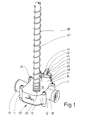
- the device shown here is a Gradient regulator or gradient pressure regulator of a drinking device for animals, especially poultry.
- the drinking device serves to supply the animals with a liquid, in particular Water that may contain additives such as medication may contain.
- the drinking device not shown in the figures is hanging in a barn to house the animals.
- the watering device has a running through the barn elongated water supply line with a for example square cross-section with rounded corners.
- a Pressure reducer arranged, the water pressure of a water feed line reduced to the operating pressure of the drinking device.
- the water supply line are regular Intervals drinking water valves arranged. By doing so The animals can use their drinking valves Cover water requirements independently.
- the water supply line is often horizontal slightly inclined. This is especially the case when a stall is erected geographically on sloping ground and / or for easy cleaning the water supply lines have an artificial gradient.
- the device according to the invention There are usually several such devices with uniform intervals along the Water supply line arranged.
- Such a drinking device is known for example from US 5 870 970.
- Regarding the basic structure of the drinking device referred to. are inclined along the Water supply pipe several slope regulators, so-called “Pressure regulators" arranged.
- Pressure regulators are a further development or Redesign of the "Pressure Regulators ".
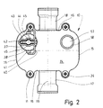
- the device has in the embodiment shown here box-shaped housing 10 with a substantially rectangular Base area (Fig. 2).
- the housing 10 is out Plastic formed. Opposite sides of the housing 10 each have two bulges 11 projecting outwards on.
- the housing 10 is formed in several parts. It sits down together from a middle housing part 12, a lower, level Base plate 13 and an upper, also flat cover plate 14.
- the middle housing part 12 is of a circumferential, upright Surround side wall, which consist of two parallel Longitudinal side walls 15 and two parallel transverse side walls 16 composes.
- a transverse side wall 16 is a water inlet connection 17 assigned while the opposite Transverse side wall 16 has a water outlet 18.
- the Water inlet connector 17 and the water outlet connector 18 are on a common axis, namely the longitudinal central axis 19 of the housing 10.
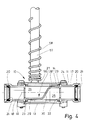
- the water inlet connector 17 and the water outlet connector 18 each have a square inner Cross-section of the same size or area with the outer Cross section of the water supply line corresponds. With Distance from the respective outer end is inside the Water inlet connector 17 and the water outlet connector 18 a Seal 20 with a circumferential, elastically deformable Sealing lip 21 arranged (Fig. 4).
- the device can be used in the water supply line. Where the device under given pressure conditions to be arranged, the water supply line separated. A short section of the Water supply line removed, so that between the mutually facing Ends of the water supply line Distance arises, which is an arrangement of the device between these ends of the cut water supply line allows.
- the device is connected to the water supply line, by each at the point of separation a short end area in the water inlet connection 17 or Water drain pipe 18 is inserted.
- the insertion depth of the respective section of the water supply line in the Water inlet connector 17 and the water outlet connector 18 is by a circumferential collar 22 on the inside of the Housing 10 facing end of the water inlet connector 17 and Water drainage pipe 18 limited.
- This collar 22 laces thereby the inner cross section of the water inlet connection 17 and of the water drainage neck 18 a little, to about to the inner free cross section of the water supply line.
- the seals 20 are in the water inlet nozzle 17 and the water outlet 18 inserted end areas the water supply line opposite the housing 10 sealed.
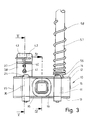
- a partition 27 is located inside the housing 10. This divides the interior of the housing 10 into two chambers 25 and 26.
- the water inlet connection opens into the lower chamber 25 17 a.
- the incoming water flows into the lower chamber 25.
- the upper chamber 26 is with the water drain pipe 18 connected so that through the upper chamber 26 water can flow through the water outlet 18.
- the partition 27 is in the course between the water inlet pipe 17 and the Water drainage socket 18 angled twice.
- the Partition 27 over a water inlet nozzle 17th horizontal edge portion 28 and one below the Water drainage pipe 18 lying, also horizontal edge section 29.
- the in different horizontal levels lying edge sections 28 and 29 are connected by a inclined middle section 30 of the partition wall 27.
- the Middle section 30 is slightly laterally offset, is located So eccentrically in the housing 10. This means that under the Water outlet 18 lying edge section 29 a larger Length than that on the other side of the middle section 30 Edge section 28 arranged at a higher level.
- opening 31 In the partition wall 27, specifically in the wider edge section 29, there is an opening 31.
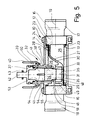
- This opening 31 is a Associated valve assembly 32 (Fig. 5).
- the valve arrangement 32 Through the valve arrangement 32, the opening 31 can be opened or opened as required getting closed. Accordingly, an inflow of water from the chamber 25 connected to the water inlet connection 17 interrupted to the chamber 26 connected to the water outlet connection 18 or released. If necessary, several can also Openings 31 and valve arrangements 32 may be provided.
- the valve arrangement 32 has a valve seat 33 which is assigned to the opening 31 in the partition 27 and one valve pin 34 movable up and down with a sealing surface 35, which corresponds to the valve seat 33.
- the elongated valve pin 34 is up and down on a vertical longitudinal central axis 36 removable.
- the valve assembly 32, in particular the Valve pin 34 is the to the chamber 26 for draining water facing top of the partition 27 assigned.
- the valve pin 34 is guided up and down in one cylindrical insertion part 37.
- the insertion part 37 forms thereby a cylindrical in the embodiment shown Guide for the valve pin 34.
- the insertion part 37 in turn is detachably arranged in a sleeve 38.
- the sleeve 38 is with the cover plate 14 connected, in the embodiment shown in one piece.
- the sleeve 38 protrudes with a smaller part into the chamber 26 inside the housing 10 while a Major part of the sleeve 38 opposite the cover plate 14 protrudes above.
- the insertion part 37 has a circumferential sealing ring 39 with which it is opposite the sleeve 38 is sealed.
- the opposite of the cover plate 14 upwards projecting part of the sleeve 38 is a securing bracket 40 assigned.
- the valve pin 34 is rotationally symmetrical, namely cylindrical, formed. It is made up of two Cylinder sections 46 of different diameters. On lower cylinder section 46 has a smaller diameter on as an upper cylinder section located above 47, the length of which in the exemplary embodiment shown is approximately that Twice the length of the lower (smaller) cylinder section Is 46. With a larger part of the lower cylinder section 46 protrudes the valve pin 34 when the valve assembly is closed 32 out of the insert 37 down. On lower end area of the smaller diameter cylinder section 46 is with a circumferential, truncated cone Provide bevel that the frustoconical sealing surface 35th forms.
- This sealing surface 35 corresponds to one accordingly trained, also frustoconical valve seat 33 in the region of the opening 31 in the partition wall 27.
- the frustoconical valve seat 33 is circumferential on the upper, arranged inner edge of an insert sleeve 48.
- the Insert sleeve 48 is inserted waterproof in a cylindrical Recess of a circumferential collar 49 of the partition 27.
- the collar 49 is the side facing the upper chamber 26 assigned to the partition 27 and surrounds the opening 31 in the Partition 27.
- the valve pin 34 is with its upper (in diameter larger) cylinder section 47 in a blind hole open at the bottom 50 guided up and down in the insertion part 37.
- the Blind hole 50 has a circumferential at the lower end Constriction 51 on. This will make the inside diameter of the Blind hole 50 constricted at the lower end of insert 37, approximately down to the smaller diameter of the lower cylinder section 46.
- valve assembly 32 The dimensions of the valve assembly 32 are made so that when closed the same the frustoconical sealing surface 35 at the lower end of the valve pin 34 with the same frustum Trained valve seat 33 on the upper inside of the Insert sleeve 48 can rest over the entire surface, that is closed valve assembly 32 a flat, frustoconical Seal between the insert sleeve 48 and the Venitl forest 34 is given.
- a paragraph 52 lies between the different diameter cylinder sections 46 and 47 of the valve pin 34 not on the constriction 51 on lower end of the blind hole 50 in the insertion part 37 (Fig. 5).
- the length of the upper (larger) cylinder section 47 of the valve pin 34 in the insert part 37 leading cylinder section the blind hole 50 is much larger than the length of the upper cylinder section 47.
- the cylindrical guide section of the Blind hole 50 about twice as long as the upper cylinder section 47 of the valve pin 34 Flush the device of valve pin 34 completely means with the entire lower cylinder section 46 in the Immerse the blind hole 50 of the insert 37. Moreover offers the blind hole 50 of the insert 37 enough Space to accommodate longer valve pins 34.
- valve pin 34 When pulled out of the sleeve 38 insert 37 is the Valve pin 34 secured here against falling out by the Constriction 51 at the lower end of the blind hole 50. Likewise is the maximum insertion depth of the valve pin 34 in the insertion part 37 delimited by a circumferential shoulder 53 in the end area the blind hole 50.
- a portion of the insert 37 is longitudinal Provide slots 54.
- slots 54 In the embodiment shown four evenly distributed over the circumference of the insertion part 37 Slot 54 provided.
- the equally large slots 54 go out from the open bottom of the insert 37 and extend until shortly before the upper step 53 of the blind hole 50. Transition areas lying between adjacent slots 54 of the insertion part 37 are elastic due to the slots 54 expandable, namely form spring tongues 55. This makes it possible, the lower constriction 51 of the blind hole 50 des Insert part 37 so that the valve pin 34th with its larger diameter cylinder section 47 through elastic expansion of the spring tongue 55 from the plug-in part 37 can be pulled out and used again if necessary.
- the sleeve 38 holds the spring tongues 55 of the male part 37 together, so that when assembled Valve arrangement 32 of the valve pin 34 in a form-fitting manner in the plug-in part 37 is held.
- the push-on socket 56 is in one piece connected to the cover plate 14 of the housing 10.
- On the push-on socket 56 is a lower region of an elongated, vertical tube 57 pushed on.
- the tube 57 is used for venting the drinking device.
- a the tube 57 outside surrounding spring 58 serves to stabilize the tube 57 and to protect it against buckling.
- the tube 57 is preferably made of transparent plastic, which makes the Water level in the tube 57 is visible and therefore the visual Pressure in the drinking device can be determined.
- the top, open end of tube 57 can be with a valve, not shown be provided. This valve can be closed when the Drinking device to be flushed with higher pressure.
- the device consists essentially of plastic. The applies especially to the housing 10.
- the valve pin 34 and the insert sleeve 48 made of a metallic material, especially stainless steel. Thereby exist that serve to seal the valve assembly 32 Surfaces from a precisely editable and resistant Material.
- valve pin 34 Because the valve pin 34 by its weight, the valve assembly 32 opens and closes, must be set to the corresponding Pressure equalization ratio, namely the difference the pressure in the chamber 25 with the water inlet connection 17 in Relationship to the chamber 26 with the water outlet 18 the inclination of the water supply line can be adjusted. A more inclined water supply line requires one heavier valve pin 34 than a less inclined water supply line. To make a corresponding setting a valve pin 34 with a appropriate weight used.
- the different levels Valve pins 34 have upper cylinder sections of different lengths 47. The lower diameter cylinder section 46 generally remains unchanged in length.
- the safety bracket 40 is first to the side pivoted so that it releases the handle 42 of the insert 37. It can then insert part 37 with valve pin 34 can be pulled out of the sleeve 38 upwards. After that Insert part 37 with the valve pin 34 from the device is separated, the valve pin 34 is removed from the insertion part 37 pulled out, the separated from the slots 54 Spring tongues 55 bent outwards by elastic deformation become. The constriction 51 widens at the lower end of the insertion part 37 so far that the valve pin 34 with the upper, larger diameter cylinder section 47 after can be pulled out of the plug 37 below. After that can another valve pin 34 under elastic deformation the spring tongues 55 inserted from below into the insertion part 37 become. By then pulling the spring tongues together 55 is in the starting position by the constriction 51st the valve pin 34 against falling out of the insert part 37 secured.
- the insert 37 By a correspondingly dimensioned length of the blind hole 50 in the plug-in part 37, which is larger than for opening the valve arrangement 32 required, it is possible to be different long valve pins 34 to assign the insert 37.
- the maximum length of the blind bore 50 in the insertion part 37 is chosen so that the valve pin 34 with the greatest length can still be moved up and down sufficiently in the plug-in part 37 is to open the valve assembly 32, also in In case of rinsing the drinking device. As a rule, that is Make blind hole 50 so long that the longest valve pin 34 can be moved so far into the insertion part 37, that it is completely in it.
- the insert 37 with the respective valve pin 34 to be exchanged as a complete unit. In this case it is not required after pulling out insert 37 out of the housing 10 the valve pin 34 from the plug 37 separate.
- the slots 54 of the cylindrical lateral surface of the insertion part 37 are omitted, so that the guide for the Valve pin 34 is completely cylindrical and no spring tongues 55 has.
- a device according to a second (not shown) embodiment the invention differs from that previously described device with respect to the valve assembly 32nd Also the valve arrangement in the one to be described here Device has a valve pin. But this is completely housed in an insert sleeve, so that that it can be moved up and down in it.
- the insert sleeve is with a lower part firmly arranged in the collar of the partition.
- the insert sleeve is stepped on the inside, namely has there over two different diameters.
- An upper part of the Insert sleeve with a larger diameter is used for mounting the valve pin.
- a lower part of the insert sleeve, which is about the height of the collar has a smaller one Diameter.
- At the transition between the smaller and the Larger diameter is preferably a conical one Valve seat. This corresponds to a sealing surface at the bottom of the valve pin by the valve pin to close the valve assembly with its sealing surface the valve seat rests.
- valve seat in the wall of the insert sleeve several through holes arranged. Preferably are about four to eight equally sized through holes distributed the circumference of the jacket of the insert sleeve.
- an upper part extends the insert sleeve up to a sleeve-like extension of the cover plate of the housing.
- This sleeve is in diameter larger than the outer diameter of the insert sleeve, so that there is an annular gap between the sleeve and the insert sleeve arises through the water to the top of the valve pin can reach.
- the top of the sleeve is through one Closing sealable.
Landscapes
- Life Sciences & Earth Sciences (AREA)
- Environmental Sciences (AREA)
- Birds (AREA)
- Animal Husbandry (AREA)
- Biodiversity & Conservation Biology (AREA)
- Devices For Dispensing Beverages (AREA)
- Measuring Fluid Pressure (AREA)
- Lift Valve (AREA)
- Control Of Fluid Pressure (AREA)
- External Artificial Organs (AREA)
- Electrical Discharge Machining, Electrochemical Machining, And Combined Machining (AREA)
- Ink Jet (AREA)
- Silver Salt Photography Or Processing Solution Therefor (AREA)
- Feeding And Watering For Cattle Raising And Animal Husbandry (AREA)
- Sampling And Sample Adjustment (AREA)
- Optical Communication System (AREA)
Applications Claiming Priority (2)
| Application Number | Priority Date | Filing Date | Title |
|---|---|---|---|
| DE19953656A DE19953656A1 (de) | 1999-11-08 | 1999-11-08 | Vorrichtung zum Ausgleich des Drucks einer Flüssigkeit und Verfahren zur Änderung des Druckausgleichsverhältnisses |
| DE19953656 | 1999-11-08 |
Publications (3)
| Publication Number | Publication Date |
|---|---|
| EP1097635A2 true EP1097635A2 (fr) | 2001-05-09 |
| EP1097635A3 EP1097635A3 (fr) | 2003-01-02 |
| EP1097635B1 EP1097635B1 (fr) | 2005-04-13 |
Family
ID=7928275
Family Applications (1)
| Application Number | Title | Priority Date | Filing Date |
|---|---|---|---|
| EP00122826A Expired - Lifetime EP1097635B1 (fr) | 1999-11-08 | 2000-10-20 | Dispositif d'équilibrage de pression de liquide et procédé pour changer la proportion d'équilibrage de pression |
Country Status (9)
| Country | Link |
|---|---|
| US (1) | US6450121B1 (fr) |
| EP (1) | EP1097635B1 (fr) |
| AT (1) | ATE292886T1 (fr) |
| BR (1) | BR0005259A (fr) |
| DE (2) | DE19953656A1 (fr) |
| DK (1) | DK1097635T3 (fr) |
| ES (1) | ES2238958T3 (fr) |
| MX (1) | MXPA00010767A (fr) |
| PT (1) | PT1097635E (fr) |
Cited By (1)
| Publication number | Priority date | Publication date | Assignee | Title |
|---|---|---|---|---|
| CN110521632A (zh) * | 2019-10-08 | 2019-12-03 | 西安禽安禽用饮水设备有限公司 | 一种智能家禽饮水控制系统 |
Families Citing this family (4)
| Publication number | Priority date | Publication date | Assignee | Title |
|---|---|---|---|---|
| WO2010115087A1 (fr) | 2009-04-03 | 2010-10-07 | Ctb, Inc. | Régulateur de pression pour système d'arrosage |
| CN102246706A (zh) * | 2011-04-22 | 2011-11-23 | 湖南瑞丹科技有限公司 | 水量自动控制型悬盖式喂水槽 |
| DE102017002034A1 (de) | 2016-07-20 | 2018-01-25 | Lubing Maschinenfabrik Ludwig Bening Gmbh & Co. Kg | Druckminderer für Tiertränken sowie Verfahren zum Verstellen mindestens eines Druckminderers für Tiertränken |
| CN113057113B (zh) * | 2021-03-18 | 2022-06-03 | 深圳市鸿昇智能科技有限公司 | 一种用于畜牧出水器的调压装置 |
Citations (1)
| Publication number | Priority date | Publication date | Assignee | Title |
|---|---|---|---|---|
| US5870970A (en) | 1994-05-25 | 1999-02-16 | Plasson Maagan Michael Industries Ltd. | Water supply system and method particularly useful for poultry houses, and water pressure reducer for use in such system and method |
Family Cites Families (12)
| Publication number | Priority date | Publication date | Assignee | Title |
|---|---|---|---|---|
| US1526249A (en) * | 1923-12-06 | 1925-02-10 | Smith James Worley | Stock waterer |
| US1622069A (en) * | 1924-03-12 | 1927-03-22 | Thomson Charles Harry | Fluid-controlling valve |
| US1870927A (en) * | 1929-09-17 | 1932-08-09 | Schoene Kurt | Valve especially for pumps and compressors |
| DE2543319A1 (de) * | 1975-09-29 | 1977-04-07 | Pfeiffer Vakuumtechnik | Schwingungsgedaempftes gewichtsbelastetes ueberdruckventil |
| US4297846A (en) * | 1980-03-14 | 1981-11-03 | Benditalia S.P.A. | Two-compartments fluid reservoir |
| US5036881A (en) * | 1989-11-01 | 1991-08-06 | Southmayd George C | Hydrostatic relief valve |
| US5141023A (en) * | 1991-05-13 | 1992-08-25 | Otis Engineering Corporation | Flow actuated safety valve |
| US5184571A (en) * | 1991-10-22 | 1993-02-09 | Avtron, Inc. | Automatically self-cleaning watering system |
| DE9212207U1 (de) * | 1992-09-10 | 1992-12-03 | Lubing Maschinenfabrik Ludwig Bening Gmbh & Co Kg, 2847 Barnstorf | Druckminderer für eine Tiertränke |
| IL126348A0 (en) * | 1997-09-30 | 1999-05-09 | Ziggity Systems Inc | Poultry watering system with fluid pressure control |
| US5967181A (en) * | 1997-11-24 | 1999-10-19 | Ctb, Inc. | Pressure regulator for watering system |
| US6009894A (en) * | 1998-10-23 | 2000-01-04 | Les Systems Et Procedes Dynapharm, Inc. | Airflow rate regulating device |
-
1999
- 1999-11-08 DE DE19953656A patent/DE19953656A1/de not_active Withdrawn
-
2000
- 2000-10-20 DE DE50010041T patent/DE50010041D1/de not_active Expired - Fee Related
- 2000-10-20 EP EP00122826A patent/EP1097635B1/fr not_active Expired - Lifetime
- 2000-10-20 PT PT00122826T patent/PT1097635E/pt unknown
- 2000-10-20 ES ES00122826T patent/ES2238958T3/es not_active Expired - Lifetime
- 2000-10-20 AT AT00122826T patent/ATE292886T1/de not_active IP Right Cessation
- 2000-10-20 DK DK00122826T patent/DK1097635T3/da active
- 2000-11-01 MX MXPA00010767A patent/MXPA00010767A/es active IP Right Grant
- 2000-11-03 US US09/705,485 patent/US6450121B1/en not_active Expired - Fee Related
- 2000-11-07 BR BR0005259-0A patent/BR0005259A/pt not_active Application Discontinuation
Patent Citations (1)
| Publication number | Priority date | Publication date | Assignee | Title |
|---|---|---|---|---|
| US5870970A (en) | 1994-05-25 | 1999-02-16 | Plasson Maagan Michael Industries Ltd. | Water supply system and method particularly useful for poultry houses, and water pressure reducer for use in such system and method |
Cited By (1)
| Publication number | Priority date | Publication date | Assignee | Title |
|---|---|---|---|---|
| CN110521632A (zh) * | 2019-10-08 | 2019-12-03 | 西安禽安禽用饮水设备有限公司 | 一种智能家禽饮水控制系统 |
Also Published As
| Publication number | Publication date |
|---|---|
| BR0005259A (pt) | 2001-07-24 |
| EP1097635A3 (fr) | 2003-01-02 |
| PT1097635E (pt) | 2005-09-30 |
| ES2238958T3 (es) | 2005-09-16 |
| DE50010041D1 (de) | 2005-05-19 |
| DK1097635T3 (da) | 2005-08-15 |
| ATE292886T1 (de) | 2005-04-15 |
| DE19953656A1 (de) | 2001-05-10 |
| EP1097635B1 (fr) | 2005-04-13 |
| US6450121B1 (en) | 2002-09-17 |
| MXPA00010767A (es) | 2003-06-17 |
Similar Documents
| Publication | Publication Date | Title |
|---|---|---|
| DE69102532T2 (de) | Bodenentwässerung. | |
| DE112019000734T5 (de) | Wirbelbrunnen | |
| DE102011051430B4 (de) | Abwasserablauf mit Geruchsverschluss | |
| EP2045403A1 (fr) | Garniture d'ecoulement avec trop-plein intégré | |
| DE202015006212U1 (de) | Ablaufanordnung | |
| EP1097635A2 (fr) | Dispositif d'équilibrage de pression de liquide et procédé pour changer la proportion d'équilibrage de pression | |
| DE202008003061U1 (de) | Klärbecken mit Auslasseinrichtung | |
| DE102018100327B4 (de) | Ablauf mit Schließorgan | |
| DE102006018612A1 (de) | Stopfen | |
| DE10204683B4 (de) | Becken | |
| EP0185109B1 (fr) | Siphon | |
| DE202015107000U1 (de) | Ablaufsystem | |
| DE3636328C2 (de) | Vorrichtung zum Einbau in das Abflußsystem von Badewannen | |
| EP1775395A1 (fr) | Dispositif d'écoulement pour installations sanitaires | |
| EP3199715A2 (fr) | Trop-plein pour un bac, en particulier évier | |
| EP1574629A1 (fr) | Armature d'écoulement pour un dispositif sanitaire, spécialement pour une cuvette de douche | |
| EP3173540B1 (fr) | Module de fermeture de trou de vidange d'une cuve et procédé de montage d'un tel module | |
| DE19847655A1 (de) | Zisternenfilter | |
| CH709249A2 (de) | Pflanzbeet-Vorrichtung. | |
| DE19821817C1 (de) | Vorrichtung zum Sammeln und zum periodischen Einleiten eines abzumessenden Quantums von Flüssigkeit in ein Rohrleitungssystem | |
| DE29808776U1 (de) | Vorrichtung zum Sammeln und zum periodischen Einleiten eines abzumessenden Quantums von Flüssigkeit in ein Rohrleitungssystem | |
| DE4414888A1 (de) | Ablaufarmatur | |
| EP4520887A1 (fr) | Bouche d'égout avec piège à odeurs | |
| DE1911510C (de) | Ablaufverschluß fur Waschbecken od dgl | |
| DE202025101378U1 (de) | Einrichtung zur Speicherung von Grauwasser und System zur Grauwasserverwendung |
Legal Events
| Date | Code | Title | Description |
|---|---|---|---|
| PUAI | Public reference made under article 153(3) epc to a published international application that has entered the european phase |
Free format text: ORIGINAL CODE: 0009012 |
|
| AK | Designated contracting states |
Kind code of ref document: A2 Designated state(s): AT BE CH CY DE DK ES FI FR GB GR IE IT LI LU MC NL PT SE |
|
| AX | Request for extension of the european patent |
Free format text: AL;LT;LV;MK;RO;SI |
|
| PUAL | Search report despatched |
Free format text: ORIGINAL CODE: 0009013 |
|
| AK | Designated contracting states |
Kind code of ref document: A3 Designated state(s): AT BE CH CY DE DK ES FI FR GB GR IE IT LI LU MC NL PT SE |
|
| AX | Request for extension of the european patent |
Free format text: AL;LT;LV;MK;RO;SI |
|
| 17P | Request for examination filed |
Effective date: 20030117 |
|
| 17Q | First examination report despatched |
Effective date: 20030520 |
|
| AKX | Designation fees paid |
Designated state(s): AT BE CH CY DE DK ES FI FR GB GR IE IT LI LU MC NL PT SE |
|
| GRAP | Despatch of communication of intention to grant a patent |
Free format text: ORIGINAL CODE: EPIDOSNIGR1 |
|
| GRAS | Grant fee paid |
Free format text: ORIGINAL CODE: EPIDOSNIGR3 |
|
| GRAA | (expected) grant |
Free format text: ORIGINAL CODE: 0009210 |
|
| AK | Designated contracting states |
Kind code of ref document: B1 Designated state(s): AT BE CH CY DE DK ES FI FR GB GR IE IT LI LU MC NL PT SE |
|
| PG25 | Lapsed in a contracting state [announced via postgrant information from national office to epo] |
Ref country code: IE Free format text: LAPSE BECAUSE OF FAILURE TO SUBMIT A TRANSLATION OF THE DESCRIPTION OR TO PAY THE FEE WITHIN THE PRESCRIBED TIME-LIMIT Effective date: 20050413 Ref country code: FI Free format text: LAPSE BECAUSE OF FAILURE TO SUBMIT A TRANSLATION OF THE DESCRIPTION OR TO PAY THE FEE WITHIN THE PRESCRIBED TIME-LIMIT Effective date: 20050413 |
|
| REG | Reference to a national code |
Ref country code: GB Ref legal event code: FG4D Free format text: NOT ENGLISH |
|
| REG | Reference to a national code |
Ref country code: CH Ref legal event code: EP |
|
| REG | Reference to a national code |
Ref country code: IE Ref legal event code: FG4D Free format text: LANGUAGE OF EP DOCUMENT: GERMAN |
|
| REF | Corresponds to: |
Ref document number: 50010041 Country of ref document: DE Date of ref document: 20050519 Kind code of ref document: P |
|
| REG | Reference to a national code |
Ref country code: GR Ref legal event code: EP Ref document number: 20050401901 Country of ref document: GR |
|
| REG | Reference to a national code |
Ref country code: SE Ref legal event code: TRGR |
|
| REG | Reference to a national code |
Ref country code: DK Ref legal event code: T3 |
|
| GBT | Gb: translation of ep patent filed (gb section 77(6)(a)/1977) |
Effective date: 20050809 |
|
| REG | Reference to a national code |
Ref country code: ES Ref legal event code: FG2A Ref document number: 2238958 Country of ref document: ES Kind code of ref document: T3 |
|
| REG | Reference to a national code |
Ref country code: PT Ref legal event code: SC4A Effective date: 20050713 |
|
| PG25 | Lapsed in a contracting state [announced via postgrant information from national office to epo] |
Ref country code: AT Free format text: LAPSE BECAUSE OF NON-PAYMENT OF DUE FEES Effective date: 20051020 Ref country code: CY Free format text: LAPSE BECAUSE OF FAILURE TO SUBMIT A TRANSLATION OF THE DESCRIPTION OR TO PAY THE FEE WITHIN THE PRESCRIBED TIME-LIMIT Effective date: 20051020 |
|
| PG25 | Lapsed in a contracting state [announced via postgrant information from national office to epo] |
Ref country code: CH Free format text: LAPSE BECAUSE OF NON-PAYMENT OF DUE FEES Effective date: 20051031 Ref country code: MC Free format text: LAPSE BECAUSE OF NON-PAYMENT OF DUE FEES Effective date: 20051031 Ref country code: LU Free format text: LAPSE BECAUSE OF NON-PAYMENT OF DUE FEES Effective date: 20051031 Ref country code: LI Free format text: LAPSE BECAUSE OF NON-PAYMENT OF DUE FEES Effective date: 20051031 |
|
| REG | Reference to a national code |
Ref country code: IE Ref legal event code: FD4D |
|
| PLBE | No opposition filed within time limit |
Free format text: ORIGINAL CODE: 0009261 |
|
| STAA | Information on the status of an ep patent application or granted ep patent |
Free format text: STATUS: NO OPPOSITION FILED WITHIN TIME LIMIT |
|
| ET | Fr: translation filed | ||
| 26N | No opposition filed |
Effective date: 20060116 |
|
| REG | Reference to a national code |
Ref country code: CH Ref legal event code: PL |
|
| PGFP | Annual fee paid to national office [announced via postgrant information from national office to epo] |
Ref country code: NL Payment date: 20081005 Year of fee payment: 9 |
|
| PGFP | Annual fee paid to national office [announced via postgrant information from national office to epo] |
Ref country code: DE Payment date: 20081021 Year of fee payment: 9 Ref country code: DK Payment date: 20081013 Year of fee payment: 9 |
|
| PGFP | Annual fee paid to national office [announced via postgrant information from national office to epo] |
Ref country code: ES Payment date: 20081121 Year of fee payment: 9 Ref country code: PT Payment date: 20081003 Year of fee payment: 9 |
|
| PGFP | Annual fee paid to national office [announced via postgrant information from national office to epo] |
Ref country code: IT Payment date: 20081029 Year of fee payment: 9 Ref country code: BE Payment date: 20081009 Year of fee payment: 9 Ref country code: SE Payment date: 20081022 Year of fee payment: 9 |
|
| PGFP | Annual fee paid to national office [announced via postgrant information from national office to epo] |
Ref country code: FR Payment date: 20081014 Year of fee payment: 9 |
|
| PGFP | Annual fee paid to national office [announced via postgrant information from national office to epo] |
Ref country code: GB Payment date: 20081015 Year of fee payment: 9 Ref country code: GR Payment date: 20081002 Year of fee payment: 9 |
|
| BERE | Be: lapsed |
Owner name: LUBING MASCHINENFABRIK LUDWIG *BENING G.M.B.H. & C Effective date: 20091031 |
|
| REG | Reference to a national code |
Ref country code: PT Ref legal event code: MM4A Free format text: LAPSE DUE TO NON-PAYMENT OF FEES Effective date: 20100420 |
|
| REG | Reference to a national code |
Ref country code: NL Ref legal event code: V1 Effective date: 20100501 |
|
| EUG | Se: european patent has lapsed | ||
| REG | Reference to a national code |
Ref country code: DK Ref legal event code: EBP |
|
| REG | Reference to a national code |
Ref country code: FR Ref legal event code: ST Effective date: 20100630 |
|
| PG25 | Lapsed in a contracting state [announced via postgrant information from national office to epo] |
Ref country code: FR Free format text: LAPSE BECAUSE OF NON-PAYMENT OF DUE FEES Effective date: 20091102 Ref country code: PT Free format text: LAPSE BECAUSE OF NON-PAYMENT OF DUE FEES Effective date: 20100420 Ref country code: NL Free format text: LAPSE BECAUSE OF NON-PAYMENT OF DUE FEES Effective date: 20100501 Ref country code: DE Free format text: LAPSE BECAUSE OF NON-PAYMENT OF DUE FEES Effective date: 20100501 |
|
| PG25 | Lapsed in a contracting state [announced via postgrant information from national office to epo] |
Ref country code: GR Free format text: LAPSE BECAUSE OF NON-PAYMENT OF DUE FEES Effective date: 20100504 Ref country code: BE Free format text: LAPSE BECAUSE OF NON-PAYMENT OF DUE FEES Effective date: 20091031 |
|
| PG25 | Lapsed in a contracting state [announced via postgrant information from national office to epo] |
Ref country code: GB Free format text: LAPSE BECAUSE OF NON-PAYMENT OF DUE FEES Effective date: 20091020 |
|
| PG25 | Lapsed in a contracting state [announced via postgrant information from national office to epo] |
Ref country code: DK Free format text: LAPSE BECAUSE OF NON-PAYMENT OF DUE FEES Effective date: 20091031 |
|
| REG | Reference to a national code |
Ref country code: ES Ref legal event code: FD2A Effective date: 20110330 |
|
| PG25 | Lapsed in a contracting state [announced via postgrant information from national office to epo] |
Ref country code: IT Free format text: LAPSE BECAUSE OF NON-PAYMENT OF DUE FEES Effective date: 20091020 |
|
| PG25 | Lapsed in a contracting state [announced via postgrant information from national office to epo] |
Ref country code: SE Free format text: LAPSE BECAUSE OF NON-PAYMENT OF DUE FEES Effective date: 20091021 |
|
| PG25 | Lapsed in a contracting state [announced via postgrant information from national office to epo] |
Ref country code: ES Free format text: LAPSE BECAUSE OF NON-PAYMENT OF DUE FEES Effective date: 20110317 |
|
| PG25 | Lapsed in a contracting state [announced via postgrant information from national office to epo] |
Ref country code: ES Free format text: LAPSE BECAUSE OF NON-PAYMENT OF DUE FEES Effective date: 20091021 |