EP1097635A2 - Device for equalizing pressure in a liquid and method for changing the pressure balance proportion - Google Patents
Device for equalizing pressure in a liquid and method for changing the pressure balance proportion Download PDFInfo
- Publication number
- EP1097635A2 EP1097635A2 EP00122826A EP00122826A EP1097635A2 EP 1097635 A2 EP1097635 A2 EP 1097635A2 EP 00122826 A EP00122826 A EP 00122826A EP 00122826 A EP00122826 A EP 00122826A EP 1097635 A2 EP1097635 A2 EP 1097635A2
- Authority
- EP
- European Patent Office
- Prior art keywords
- valve
- valve pin
- sleeve
- housing
- insert
- Prior art date
- Legal status (The legal status is an assumption and is not a legal conclusion. Google has not performed a legal analysis and makes no representation as to the accuracy of the status listed.)
- Granted
Links
- 239000007788 liquid Substances 0.000 title claims abstract description 29
- 238000000034 method Methods 0.000 title claims description 10
- 238000007789 sealing Methods 0.000 claims abstract description 17
- 241001465754 Metazoa Species 0.000 claims abstract description 9
- 238000005192 partition Methods 0.000 claims description 17
- 210000002105 tongue Anatomy 0.000 claims description 10
- 230000005489 elastic deformation Effects 0.000 claims description 4
- 239000007769 metal material Substances 0.000 claims description 2
- 229910001220 stainless steel Inorganic materials 0.000 claims description 2
- 239000010935 stainless steel Substances 0.000 claims description 2
- XLYOFNOQVPJJNP-UHFFFAOYSA-N water Substances O XLYOFNOQVPJJNP-UHFFFAOYSA-N 0.000 abstract description 71
- 230000035622 drinking Effects 0.000 abstract description 16
- 238000003780 insertion Methods 0.000 description 20
- 230000037431 insertion Effects 0.000 description 20
- 210000002445 nipple Anatomy 0.000 description 3
- 229920003023 plastic Polymers 0.000 description 3
- 244000144977 poultry Species 0.000 description 2
- 230000007704 transition Effects 0.000 description 2
- 239000000654 additive Substances 0.000 description 1
- 230000015572 biosynthetic process Effects 0.000 description 1
- 239000003638 chemical reducing agent Substances 0.000 description 1
- 238000004140 cleaning Methods 0.000 description 1
- 239000003651 drinking water Substances 0.000 description 1
- 235000020188 drinking water Nutrition 0.000 description 1
- 229940079593 drug Drugs 0.000 description 1
- 239000003814 drug Substances 0.000 description 1
- 210000003746 feather Anatomy 0.000 description 1
- 238000011010 flushing procedure Methods 0.000 description 1
- 238000005755 formation reaction Methods 0.000 description 1
- 230000005484 gravity Effects 0.000 description 1
- 239000000463 material Substances 0.000 description 1
- 238000000465 moulding Methods 0.000 description 1
- 230000002093 peripheral effect Effects 0.000 description 1
- 238000000926 separation method Methods 0.000 description 1
- 238000013022 venting Methods 0.000 description 1
- 230000000007 visual effect Effects 0.000 description 1
Images
Classifications
-
- A—HUMAN NECESSITIES
- A01—AGRICULTURE; FORESTRY; ANIMAL HUSBANDRY; HUNTING; TRAPPING; FISHING
- A01K—ANIMAL HUSBANDRY; AVICULTURE; APICULTURE; PISCICULTURE; FISHING; REARING OR BREEDING ANIMALS, NOT OTHERWISE PROVIDED FOR; NEW BREEDS OF ANIMALS
- A01K39/00—Feeding or drinking appliances for poultry or other birds
- A01K39/02—Drinking appliances
- A01K39/0213—Nipple drinkers
Definitions
- the invention relates to a device for balancing the Pressure of a liquid, especially one preferably inclined liquid line for feeding drinking nipples for animals according to the preamble of claim 1. Furthermore The invention relates to a method for changing the Pressure balance ratio in particular an inclined Liquid line for feeding drinking nipples for animals according to the preamble of claim 10.
- Devices of the type mentioned here are in technical jargon referred to as a gradient controller. They are preferably used in the course of inclined liquid lines for feeding Drinking nipples for animals, especially poultry. With inclined Liquid lines the pressure increases in the course of the same.
- the gradient controls are used to control the pressure over the course of the inclined liquid line to even out.
- the object of the invention is a device (gradient controller) and a method of the beginning to create the type mentioned, making it easier and more reliable Way the pressure along the sloping liquid lines Is adaptable accordingly.
- valve assembly preferably has cylindrical valve pin which can be through Dead weight closes, can with the well-known incline or the spring pressure regulator required. Moreover the valve pin ensures reliable opening and Close the valve assembly because it is preferred by its cylindrical shape move up and down safely leaves.
- valve arrangement of a chamber for allocate draining liquid This allows the valve pin vertically above the chamber of the inflowing liquid to be ordered. Because of this, the movable up and down Valve pin due to its own weight the valve arrangement conclude.
- Valve pin preferably on its underside with a conical, in particular frustoconical, sealing surface.
- This frustoconical sealing surface corresponds to a likewise conical, in particular frustoconical Valve seat.
- the guide for the valve pin longer than the length of the same.
- the guide has a 1.5 to 2 times the length of the Valve pin. This can be used to flush the liquid line the valve pin so far from the valve seat in preferably a partition between the chambers that move away Sufficiently large liquid flow for flushing the liquid line can also flow through the valve assembly.
- the Incline controller according to the invention thereby leaves an unhindered Rinse the drinking device.
- the guide for the valve pin is provided in to provide a sleeve-like insertion part, which in a corresponding socket or sleeve of the housing arranged is. It can be so with the plug-in part of the valve pin Valve arrangement from the socket arranged on the housing or Take out the gradient regulator sleeve, for example to Clean the valve assembly.
- the Valve pin To the insert part together with to be able to assemble and disassemble the valve pin is the Valve pin in the plug-in part secured against falling out.
- the insertion part preferably has spring tongues which, due to an elastic deformation, separates the Allow valve pin from plug-in part if the valve pin to be replaced.
- valve assembly with valve bodies of different weight provided to the pressure compensation ratio of the gradient controller to change.
- the slope regulator With a comparatively heavy valve body the slope regulator carries a larger pressure difference between the liquid flowing into the chamber and the chamber of the flowing liquid.
- an easier one Valve body to lower pressure difference in through the Valve arrangement connected chambers that way is one simple and inexpensive change of the gradient controller achievable pressure conditions possible.
- valve body is co-located with the plug-in part replaced.
- the extractable in the housing of the Slope part arranged in the incline is easy to use assemble and disassemble. Removing the valve body from the Insert part can then be superfluous, so that inside it is possible to retrofit the gradient controller in the shortest possible time.
- plug-in part it is also possible to use the plug-in part together with pull the valve body out of the sleeve of the housing and to replace the valve body when the insert is removed, by separating it from the plug-in part and by another Valve body, especially a heavier or lighter one Valve pin, is replaced. It can then always be the same plug-in part used when according to a preferred embodiment the invention the different valve body or valve pins not in diameter, but only in differ in length.
- the device shown here is a Gradient regulator or gradient pressure regulator of a drinking device for animals, especially poultry.
- the drinking device serves to supply the animals with a liquid, in particular Water that may contain additives such as medication may contain.
- the drinking device not shown in the figures is hanging in a barn to house the animals.
- the watering device has a running through the barn elongated water supply line with a for example square cross-section with rounded corners.
- a Pressure reducer arranged, the water pressure of a water feed line reduced to the operating pressure of the drinking device.
- the water supply line are regular Intervals drinking water valves arranged. By doing so The animals can use their drinking valves Cover water requirements independently.
- the water supply line is often horizontal slightly inclined. This is especially the case when a stall is erected geographically on sloping ground and / or for easy cleaning the water supply lines have an artificial gradient.
- the device according to the invention There are usually several such devices with uniform intervals along the Water supply line arranged.
- Such a drinking device is known for example from US 5 870 970.
- Regarding the basic structure of the drinking device referred to. are inclined along the Water supply pipe several slope regulators, so-called “Pressure regulators" arranged.
- Pressure regulators are a further development or Redesign of the "Pressure Regulators ".
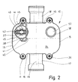
- the device has in the embodiment shown here box-shaped housing 10 with a substantially rectangular Base area (Fig. 2).
- the housing 10 is out Plastic formed. Opposite sides of the housing 10 each have two bulges 11 projecting outwards on.
- the housing 10 is formed in several parts. It sits down together from a middle housing part 12, a lower, level Base plate 13 and an upper, also flat cover plate 14.
- the middle housing part 12 is of a circumferential, upright Surround side wall, which consist of two parallel Longitudinal side walls 15 and two parallel transverse side walls 16 composes.
- a transverse side wall 16 is a water inlet connection 17 assigned while the opposite Transverse side wall 16 has a water outlet 18.
- the Water inlet connector 17 and the water outlet connector 18 are on a common axis, namely the longitudinal central axis 19 of the housing 10.
- the water inlet connector 17 and the water outlet connector 18 each have a square inner Cross-section of the same size or area with the outer Cross section of the water supply line corresponds. With Distance from the respective outer end is inside the Water inlet connector 17 and the water outlet connector 18 a Seal 20 with a circumferential, elastically deformable Sealing lip 21 arranged (Fig. 4).
- the device can be used in the water supply line. Where the device under given pressure conditions to be arranged, the water supply line separated. A short section of the Water supply line removed, so that between the mutually facing Ends of the water supply line Distance arises, which is an arrangement of the device between these ends of the cut water supply line allows.
- the device is connected to the water supply line, by each at the point of separation a short end area in the water inlet connection 17 or Water drain pipe 18 is inserted.
- the insertion depth of the respective section of the water supply line in the Water inlet connector 17 and the water outlet connector 18 is by a circumferential collar 22 on the inside of the Housing 10 facing end of the water inlet connector 17 and Water drainage pipe 18 limited.
- This collar 22 laces thereby the inner cross section of the water inlet connection 17 and of the water drainage neck 18 a little, to about to the inner free cross section of the water supply line.
- the seals 20 are in the water inlet nozzle 17 and the water outlet 18 inserted end areas the water supply line opposite the housing 10 sealed.
- a partition 27 is located inside the housing 10. This divides the interior of the housing 10 into two chambers 25 and 26.
- the water inlet connection opens into the lower chamber 25 17 a.
- the incoming water flows into the lower chamber 25.
- the upper chamber 26 is with the water drain pipe 18 connected so that through the upper chamber 26 water can flow through the water outlet 18.
- the partition 27 is in the course between the water inlet pipe 17 and the Water drainage socket 18 angled twice.
- the Partition 27 over a water inlet nozzle 17th horizontal edge portion 28 and one below the Water drainage pipe 18 lying, also horizontal edge section 29.
- the in different horizontal levels lying edge sections 28 and 29 are connected by a inclined middle section 30 of the partition wall 27.
- the Middle section 30 is slightly laterally offset, is located So eccentrically in the housing 10. This means that under the Water outlet 18 lying edge section 29 a larger Length than that on the other side of the middle section 30 Edge section 28 arranged at a higher level.
- opening 31 In the partition wall 27, specifically in the wider edge section 29, there is an opening 31.
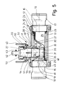
- This opening 31 is a Associated valve assembly 32 (Fig. 5).
- the valve arrangement 32 Through the valve arrangement 32, the opening 31 can be opened or opened as required getting closed. Accordingly, an inflow of water from the chamber 25 connected to the water inlet connection 17 interrupted to the chamber 26 connected to the water outlet connection 18 or released. If necessary, several can also Openings 31 and valve arrangements 32 may be provided.
- the valve arrangement 32 has a valve seat 33 which is assigned to the opening 31 in the partition 27 and one valve pin 34 movable up and down with a sealing surface 35, which corresponds to the valve seat 33.
- the elongated valve pin 34 is up and down on a vertical longitudinal central axis 36 removable.
- the valve assembly 32, in particular the Valve pin 34 is the to the chamber 26 for draining water facing top of the partition 27 assigned.
- the valve pin 34 is guided up and down in one cylindrical insertion part 37.
- the insertion part 37 forms thereby a cylindrical in the embodiment shown Guide for the valve pin 34.
- the insertion part 37 in turn is detachably arranged in a sleeve 38.
- the sleeve 38 is with the cover plate 14 connected, in the embodiment shown in one piece.
- the sleeve 38 protrudes with a smaller part into the chamber 26 inside the housing 10 while a Major part of the sleeve 38 opposite the cover plate 14 protrudes above.
- the insertion part 37 has a circumferential sealing ring 39 with which it is opposite the sleeve 38 is sealed.
- the opposite of the cover plate 14 upwards projecting part of the sleeve 38 is a securing bracket 40 assigned.
- the valve pin 34 is rotationally symmetrical, namely cylindrical, formed. It is made up of two Cylinder sections 46 of different diameters. On lower cylinder section 46 has a smaller diameter on as an upper cylinder section located above 47, the length of which in the exemplary embodiment shown is approximately that Twice the length of the lower (smaller) cylinder section Is 46. With a larger part of the lower cylinder section 46 protrudes the valve pin 34 when the valve assembly is closed 32 out of the insert 37 down. On lower end area of the smaller diameter cylinder section 46 is with a circumferential, truncated cone Provide bevel that the frustoconical sealing surface 35th forms.
- This sealing surface 35 corresponds to one accordingly trained, also frustoconical valve seat 33 in the region of the opening 31 in the partition wall 27.
- the frustoconical valve seat 33 is circumferential on the upper, arranged inner edge of an insert sleeve 48.
- the Insert sleeve 48 is inserted waterproof in a cylindrical Recess of a circumferential collar 49 of the partition 27.
- the collar 49 is the side facing the upper chamber 26 assigned to the partition 27 and surrounds the opening 31 in the Partition 27.
- the valve pin 34 is with its upper (in diameter larger) cylinder section 47 in a blind hole open at the bottom 50 guided up and down in the insertion part 37.
- the Blind hole 50 has a circumferential at the lower end Constriction 51 on. This will make the inside diameter of the Blind hole 50 constricted at the lower end of insert 37, approximately down to the smaller diameter of the lower cylinder section 46.
- valve assembly 32 The dimensions of the valve assembly 32 are made so that when closed the same the frustoconical sealing surface 35 at the lower end of the valve pin 34 with the same frustum Trained valve seat 33 on the upper inside of the Insert sleeve 48 can rest over the entire surface, that is closed valve assembly 32 a flat, frustoconical Seal between the insert sleeve 48 and the Venitl forest 34 is given.
- a paragraph 52 lies between the different diameter cylinder sections 46 and 47 of the valve pin 34 not on the constriction 51 on lower end of the blind hole 50 in the insertion part 37 (Fig. 5).
- the length of the upper (larger) cylinder section 47 of the valve pin 34 in the insert part 37 leading cylinder section the blind hole 50 is much larger than the length of the upper cylinder section 47.
- the cylindrical guide section of the Blind hole 50 about twice as long as the upper cylinder section 47 of the valve pin 34 Flush the device of valve pin 34 completely means with the entire lower cylinder section 46 in the Immerse the blind hole 50 of the insert 37. Moreover offers the blind hole 50 of the insert 37 enough Space to accommodate longer valve pins 34.
- valve pin 34 When pulled out of the sleeve 38 insert 37 is the Valve pin 34 secured here against falling out by the Constriction 51 at the lower end of the blind hole 50. Likewise is the maximum insertion depth of the valve pin 34 in the insertion part 37 delimited by a circumferential shoulder 53 in the end area the blind hole 50.
- a portion of the insert 37 is longitudinal Provide slots 54.
- slots 54 In the embodiment shown four evenly distributed over the circumference of the insertion part 37 Slot 54 provided.
- the equally large slots 54 go out from the open bottom of the insert 37 and extend until shortly before the upper step 53 of the blind hole 50. Transition areas lying between adjacent slots 54 of the insertion part 37 are elastic due to the slots 54 expandable, namely form spring tongues 55. This makes it possible, the lower constriction 51 of the blind hole 50 des Insert part 37 so that the valve pin 34th with its larger diameter cylinder section 47 through elastic expansion of the spring tongue 55 from the plug-in part 37 can be pulled out and used again if necessary.
- the sleeve 38 holds the spring tongues 55 of the male part 37 together, so that when assembled Valve arrangement 32 of the valve pin 34 in a form-fitting manner in the plug-in part 37 is held.
- the push-on socket 56 is in one piece connected to the cover plate 14 of the housing 10.
- On the push-on socket 56 is a lower region of an elongated, vertical tube 57 pushed on.
- the tube 57 is used for venting the drinking device.
- a the tube 57 outside surrounding spring 58 serves to stabilize the tube 57 and to protect it against buckling.
- the tube 57 is preferably made of transparent plastic, which makes the Water level in the tube 57 is visible and therefore the visual Pressure in the drinking device can be determined.
- the top, open end of tube 57 can be with a valve, not shown be provided. This valve can be closed when the Drinking device to be flushed with higher pressure.
- the device consists essentially of plastic. The applies especially to the housing 10.
- the valve pin 34 and the insert sleeve 48 made of a metallic material, especially stainless steel. Thereby exist that serve to seal the valve assembly 32 Surfaces from a precisely editable and resistant Material.
- valve pin 34 Because the valve pin 34 by its weight, the valve assembly 32 opens and closes, must be set to the corresponding Pressure equalization ratio, namely the difference the pressure in the chamber 25 with the water inlet connection 17 in Relationship to the chamber 26 with the water outlet 18 the inclination of the water supply line can be adjusted. A more inclined water supply line requires one heavier valve pin 34 than a less inclined water supply line. To make a corresponding setting a valve pin 34 with a appropriate weight used.
- the different levels Valve pins 34 have upper cylinder sections of different lengths 47. The lower diameter cylinder section 46 generally remains unchanged in length.
- the safety bracket 40 is first to the side pivoted so that it releases the handle 42 of the insert 37. It can then insert part 37 with valve pin 34 can be pulled out of the sleeve 38 upwards. After that Insert part 37 with the valve pin 34 from the device is separated, the valve pin 34 is removed from the insertion part 37 pulled out, the separated from the slots 54 Spring tongues 55 bent outwards by elastic deformation become. The constriction 51 widens at the lower end of the insertion part 37 so far that the valve pin 34 with the upper, larger diameter cylinder section 47 after can be pulled out of the plug 37 below. After that can another valve pin 34 under elastic deformation the spring tongues 55 inserted from below into the insertion part 37 become. By then pulling the spring tongues together 55 is in the starting position by the constriction 51st the valve pin 34 against falling out of the insert part 37 secured.
- the insert 37 By a correspondingly dimensioned length of the blind hole 50 in the plug-in part 37, which is larger than for opening the valve arrangement 32 required, it is possible to be different long valve pins 34 to assign the insert 37.
- the maximum length of the blind bore 50 in the insertion part 37 is chosen so that the valve pin 34 with the greatest length can still be moved up and down sufficiently in the plug-in part 37 is to open the valve assembly 32, also in In case of rinsing the drinking device. As a rule, that is Make blind hole 50 so long that the longest valve pin 34 can be moved so far into the insertion part 37, that it is completely in it.
- the insert 37 with the respective valve pin 34 to be exchanged as a complete unit. In this case it is not required after pulling out insert 37 out of the housing 10 the valve pin 34 from the plug 37 separate.
- the slots 54 of the cylindrical lateral surface of the insertion part 37 are omitted, so that the guide for the Valve pin 34 is completely cylindrical and no spring tongues 55 has.
- a device according to a second (not shown) embodiment the invention differs from that previously described device with respect to the valve assembly 32nd Also the valve arrangement in the one to be described here Device has a valve pin. But this is completely housed in an insert sleeve, so that that it can be moved up and down in it.
- the insert sleeve is with a lower part firmly arranged in the collar of the partition.
- the insert sleeve is stepped on the inside, namely has there over two different diameters.
- An upper part of the Insert sleeve with a larger diameter is used for mounting the valve pin.
- a lower part of the insert sleeve, which is about the height of the collar has a smaller one Diameter.
- At the transition between the smaller and the Larger diameter is preferably a conical one Valve seat. This corresponds to a sealing surface at the bottom of the valve pin by the valve pin to close the valve assembly with its sealing surface the valve seat rests.
- valve seat in the wall of the insert sleeve several through holes arranged. Preferably are about four to eight equally sized through holes distributed the circumference of the jacket of the insert sleeve.
- an upper part extends the insert sleeve up to a sleeve-like extension of the cover plate of the housing.
- This sleeve is in diameter larger than the outer diameter of the insert sleeve, so that there is an annular gap between the sleeve and the insert sleeve arises through the water to the top of the valve pin can reach.
- the top of the sleeve is through one Closing sealable.
Landscapes
- Life Sciences & Earth Sciences (AREA)
- Environmental Sciences (AREA)
- Birds (AREA)
- Animal Husbandry (AREA)
- Biodiversity & Conservation Biology (AREA)
- Devices For Dispensing Beverages (AREA)
- Measuring Fluid Pressure (AREA)
- Lift Valve (AREA)
- Control Of Fluid Pressure (AREA)
- Sampling And Sample Adjustment (AREA)
- Optical Communication System (AREA)
- Ink Jet (AREA)
- Silver Salt Photography Or Processing Solution Therefor (AREA)
- Electrical Discharge Machining, Electrochemical Machining, And Combined Machining (AREA)
- External Artificial Organs (AREA)
- Feeding And Watering For Cattle Raising And Animal Husbandry (AREA)
Abstract
Description
Die Erfindung betrifft eine Vorrichtung zum Ausgleich des
Drucks einer Flüssigkeit, insbesondere einer vorzugsweise
geneigten Flüssigkeitsleitung zur Speisung von Tränkenippeln
für Tiere gemäß dem Oberbegriff des Anspruchs 1. Des weiteren
betrifft die Erfindung ein Verfahren zur Änderung des
Druckausgleichsverhältnisses in insbesondere einer geneigten
Flüssigkeitsleitung zur Speisung von Tränkenippeln für Tiere
gemäß dem Oberbegriff des Anspruchs 10.The invention relates to a device for balancing the
Pressure of a liquid, especially one preferably
inclined liquid line for feeding drinking nipples
for animals according to the preamble of claim 1. Furthermore
The invention relates to a method for changing the
Pressure balance ratio in particular an inclined
Liquid line for feeding drinking nipples for animals
according to the preamble of
Vorrichtungen der hier angesprochenen Art werden im Fachjargon als Gefälleregler bezeichnet. Sie finden bevorzugt Verwendung im Verlauf geneigter Flüssigkeitsleitungen zur Speisung von Tränkenippeln für Tiere, insbesondere Geflügel. Bei geneigten Flüssigkeitsleitungen steigt der Druck im Verlauf derselben an. Die Gefälleregler dienen dazu, den Druck im Verlauf der geneigten Flüssigkeitsleitung zu vergleichmäßigen.Devices of the type mentioned here are in technical jargon referred to as a gradient controller. They are preferably used in the course of inclined liquid lines for feeding Drinking nipples for animals, especially poultry. With inclined Liquid lines the pressure increases in the course of the same. The gradient controls are used to control the pressure over the course of the inclined liquid line to even out.
Es sind Gefälleregler bekannt, die über eine Ventilanordnung verfügen, die einen federbeaufschlagten Ventilkörper aufweist. Die dazu erforderlichen Federn führen in der Praxis häufig zu Problemen. Beispielsweise ändern die Federn mit zunehmendem Alter ihre Federcharakteristik, wodurch der Druck in der geneigten Flüssigkeitsleitung nur unzureichend verändert wird. Darüber hinaus können die Federn durch einen Bruch oder dergleichen mit der Zeit versagen. Die bekannten Gefälleregler arbeiten somit nur unzuverlässig. Ein weiterer Nachteil der bekannten Gefälleregler besteht darin, dass sie keine Veränderung des Druckverhältnisses zulassen, wenn sich die Einsatzbedingungen ändern.Gradients are known which have a valve arrangement have a spring-loaded valve body. The springs required for this often lead in practice Problems. For example, the springs change with increasing Age their spring characteristics, reducing the pressure in the inclined liquid line is insufficiently changed. In addition, the springs can break or the like fail over time. The well-known gradient regulators therefore work only unreliably. Another disadvantage of Known slope regulator is that there is no change allow the pressure ratio if the operating conditions to change.
Hiervon ausgehend liegt der Erfindung die Aufgabe zugrunde, eine Vorrichtung (Gefälleregler) und ein Verfahren der eingangs genannten Art zu schaffen, womit in einfacher und zuverlässiger Weise der Druck entlang geneigter Flüssigkeitsleitungen den Verhältnissen entsprechend anpassbar ist.Proceeding from this, the object of the invention is a device (gradient controller) and a method of the beginning to create the type mentioned, making it easier and more reliable Way the pressure along the sloping liquid lines Is adaptable accordingly.
Eine Vorrichtung zur Lösung dieser Aufgabe weist die Merkmale des Anspruchs 1 auf. Dadurch, dass die Ventilanordnung einen vorzugsweise zylindrischen Ventilstift aufweist, der durch sein Eigengewicht schließt, kann die beim bekannten Gefälleregler bzw. Gefälledruckregler erforderliche Feder entfallen. Außerdem gewährleistet der Ventilstift ein zuverlässiges Öffnen und Schließen der Ventilanordnung, weil er durch seine vorzugsweise zylindrische Gestalt sich sicher auf- und abbewegbar führen lässt.A device for solving this problem has the features of claim 1. The fact that the valve assembly preferably has cylindrical valve pin which can be through Dead weight closes, can with the well-known incline or the spring pressure regulator required. Moreover the valve pin ensures reliable opening and Close the valve assembly because it is preferred by its cylindrical shape move up and down safely leaves.
Weiterhin ist vorgesehen, die Ventilanordnung einer Kammer für abfließende Flüssigkeit zuzuordnen. Dadurch kann der Ventilstift senkrecht über der Kammer der zufließenden Flüssigkeit angeordnet werden. Aufgrund dessen kann der auf- und abbewegbare Ventilstift durch sein Eigengewicht die Ventilanordnung schließen. It is also provided that the valve arrangement of a chamber for allocate draining liquid. This allows the valve pin vertically above the chamber of the inflowing liquid to be ordered. Because of this, the movable up and down Valve pin due to its own weight the valve arrangement conclude.
Gemäß einer bevorzugten Ausgestaltung der Erfindung ist der Ventilstift vorzugsweise an seiner Unterseite mit einer kegeligen, insbesondere kegelstumpfartigen, Dichtfläche versehen. Diese kegelstumpfartige Dichtfläche korrespondiert mit einem ebenfalls kegelig, insbesondere kegelstumpfartig, ausgebildeten Ventilsitz. Auf diese Weise wird eine zulässige Dichtung gewährleistet, wenn die Dichtfläche des Ventilstifts auf dem Ventilsitz aufliegt. Ein schwerkraftbedingtes zuverlässiges Schließen der Ventilanordnung ist dadurch gewährleistet, und zwar auch schon bei kleinen Ventilstiften, die nur über ein geringes Eigengewicht verfügen.According to a preferred embodiment of the invention Valve pin preferably on its underside with a conical, in particular frustoconical, sealing surface. This frustoconical sealing surface corresponds to a likewise conical, in particular frustoconical Valve seat. In this way it becomes a permissible Seal ensures when the sealing surface of the valve pin rests on the valve seat. A reliable due to gravity Closing of the valve arrangement is ensured even with small valve pins that only have a low weight.
Gemäß einer bevorzugten Ausgestaltung der Erfindung ist die Führung für den Ventilstift länger als die Länge desselben. Insbesondere weist die Führung eine 1,5- bis 2-fache Länge des Ventilstifts auf. Dadurch kann zum Spülen der Flüssigkeitsleitung der Ventilstift so weit vom Ventilsitz in vorzugsweise einer Trennwand zwischen den Kammern wegbewegt werden, dass ein zum Spülen der Flüssigkeitsleitung ausreichend großer Flüssigkeitsstrom auch durch die Ventilanordnung strömen kann. Der erfindungsgemäße Gefälleregler lässt dadurch ein ungehindertes Spülen der Tränkeeinrichtung zu.According to a preferred embodiment of the invention Guide for the valve pin longer than the length of the same. In particular, the guide has a 1.5 to 2 times the length of the Valve pin. This can be used to flush the liquid line the valve pin so far from the valve seat in preferably a partition between the chambers that move away Sufficiently large liquid flow for flushing the liquid line can also flow through the valve assembly. The Incline controller according to the invention thereby leaves an unhindered Rinse the drinking device.
Des weiteren ist vorgesehen, die Führung für den Ventilstift in einem hülsenartigen Einsteckteil vorzusehen, das in einer korrespondierenden Buchse bzw. Hülse des Gehäuses angeordnet ist. Es lässt sich so mit dem Einsteckteil der Ventilstift der Ventilanordnung aus der am Gehäuse angeordneten Buchse oder Hülse des Gefällereglers herausnehmen, beispielsweise zum Reinigen der Ventilanordnung. Um das Einsteckteil zusammen mit dem Ventilstift montieren und demontieren zu können, ist der Ventilstift im Einsteckteil gegen Herausfallen gesichert. Vorzugsweise weist zu diesem Zweck das Einsteckteil Federzungen auf, die durch eine elastische Verformung ein Trennen des Ventilstifts vom Einsteckteil ermöglichen, wenn der Ventilstift ausgetauscht werden soll. Furthermore, the guide for the valve pin is provided in to provide a sleeve-like insertion part, which in a corresponding socket or sleeve of the housing arranged is. It can be so with the plug-in part of the valve pin Valve arrangement from the socket arranged on the housing or Take out the gradient regulator sleeve, for example to Clean the valve assembly. To the insert part together with to be able to assemble and disassemble the valve pin is the Valve pin in the plug-in part secured against falling out. For this purpose, the insertion part preferably has spring tongues which, due to an elastic deformation, separates the Allow valve pin from plug-in part if the valve pin to be replaced.
Ein Verfahren zur Lösung der eingangs genannten Aufgabe weist
die Maßnahmen des Anspruchs 10 auf. Demnach wird die Ventilanordnung
mit Ventilkörpern unterschiedlichen Eigengewichts
versehen, um das Druckausgleichsverhältnis des Gefällereglers
zu ändern. Bei einem vergleichsweise schweren Ventilkörper
führt der Gefälleregler eine größere Druckdifferenz zwischen
der der Kammer zufließenden Flüssigkeit und der Kammer der
abfließenden Flüssigkeit herbei. Umgekehrt führt ein leichterer
Ventilkörper zu geringerem Druckunterschied in den durch die
Ventilanordnung verbundenen Kammern. Auf diese Weise ist eine
einfache und kostengünstige Veränderung der vom Gefälleregler
herbeiführbaren Druckverhältnisse möglich.A method for solving the problem mentioned at the outset
the measures of
Beim bevorzugten Verfahren wird der Ventilkörper zusammen mit dem Einsteckteil ausgetauscht. Das herausziehbar im Gehäuse des Gefällereglers angeordnete Einsteckteil lässt sich leicht montieren und demontieren. Ein Ausbau des Ventilkörpers aus dem Einsteckteil kann sich dann erübrigen, so dass innerhalb kürzester Zeit eine Umrüstung des Gefällereglers möglich ist.In the preferred method, the valve body is co-located with the plug-in part replaced. The extractable in the housing of the Slope part arranged in the incline is easy to use assemble and disassemble. Removing the valve body from the Insert part can then be superfluous, so that inside it is possible to retrofit the gradient controller in the shortest possible time.
Alternativ ist es auch möglich, das Einsteckteil zusammen mit dem Ventilkörper aus der Hülse des Gehäuses herauszuziehen und bei demontiertem Einsteckteil den Ventilkörper zu tauschen, indem dieser vom Einsteckteil getrennt und durch einen anderen Ventilkörper, insbesondere einen schwereren oder leichteren Ventilstift, ersetzt wird. Es kann dann stets das gleiche Einsteckteil verwendet werden, wenn gemäß einer bevorzugten Ausführungsform der Erfindung sich die unterschiedlichen Ventilkörper bzw. Ventilstifte nicht im Durchmesser, sondern nur in der Länge unterscheiden.Alternatively, it is also possible to use the plug-in part together with pull the valve body out of the sleeve of the housing and to replace the valve body when the insert is removed, by separating it from the plug-in part and by another Valve body, especially a heavier or lighter one Valve pin, is replaced. It can then always be the same plug-in part used when according to a preferred embodiment the invention the different valve body or valve pins not in diameter, but only in differ in length.
Ein bevorzugtes Ausführungsbeispiel der Erfindung und das erfindungsgemäße Verfahren werden nachfolgend anhand der Zeichnung näher erläutert. In dieser zeigen:
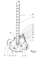
- Fig. 1
- eine perspektivische Darstellung der Vorrichtung,
- Fig. 2
- eine Draufsicht auf die Vorrichtung der Fig. 1,
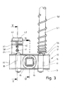
- Fig. 3
- eine Seitenansicht mit Blick auf einen Wasserzulauf,
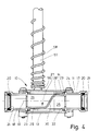
- Fig. 4
- einen Schnitt IV-IV durch die Vorrichtung, und
- Fig. 5
- einen Schnitt V-V durch die Vorrichtung.
- Fig. 1
- a perspective view of the device,
- Fig. 2
- 2 shows a top view of the device of FIG. 1,
- Fig. 3
- a side view overlooking a water inlet,
- Fig. 4
- a section IV-IV through the device, and
- Fig. 5
- a section VV through the device.
Bei der hier gezeigten Vorrichtung handelt es sich um einen Gefälleregler bzw. Gefälledruckregler einer Tränkeeinrichtung für Tiere, insbesondere Geflügel. Die Tränkeeinrichtung dient zur Versorgung der Tiere mit einer Flüssigkeit, insbesondere Wasser, das gegebenenfalls Zusätze wie zum Beispiel Medikamente enthalten kann.The device shown here is a Gradient regulator or gradient pressure regulator of a drinking device for animals, especially poultry. The drinking device serves to supply the animals with a liquid, in particular Water that may contain additives such as medication may contain.
Die im übrigen in den Figuren nicht gezeigte Tränkeeinrichtung ist hängend in einem Stall zur Aufnahme der Tiere angeordnet. Die Tränkevorrichtung verfügt über eine durch den Stall verlaufende, längliche Wasserversorgungsleitung mit einem beispielsweise viereckigen, gerundete Ecken aufweisenden Querschnitt. Am Wassereinlauf der Wasserversorgungsleitung ist ein Druckminderer angeordnet, der den Wasserdruck einer Wasserspeiseleitung auf den Betriebsdruck der Tränkeeinrichtung reduziert. Entlang der Wasserversorgungsleitung sind in regelmäßigen Abständen Tränkeventile angeordnet. Durch entsprechendes Betätigen der Tränkeventile können die Tiere ihren Wasserbedarf selbstständig decken.The drinking device not shown in the figures is hanging in a barn to house the animals. The watering device has a running through the barn elongated water supply line with a for example square cross-section with rounded corners. At the water inlet of the water supply line is a Pressure reducer arranged, the water pressure of a water feed line reduced to the operating pressure of the drinking device. Along the water supply line are regular Intervals drinking water valves arranged. By doing so The animals can use their drinking valves Cover water requirements independently.
Die Wasserversorgungsleitung verläuft vielfach zur Horizontalen leicht geneigt. Das ist insbesondere der Fall, wenn ein Stall geographisch bedingt auf schrägem Untergrund errichtet wird und/oder zum einfachen Reinigen die Wasserversorgungsleitungen ein künstliches Gefälle aufweisen. In solchen ausgehend von der Wassereinspeisung abwärtsgeneigt verlaufenden Wasserversorgungsleitungen steigt der Druck im Verlauf derselben stetig an. Zur Vergleichmäßigung des Wasserdrucks in solchen schräg verlaufenden Wasserversorgungsleitungen dient die erfindungsgemäße Vorrichtung. In der Regel sind mehrere solcher Vorrichtungen mit gleichmäßigen Abständen entlang der Wasserversorgungsleitung angeordnet. Eine solche Tränkeeinrichtung ist beispielsweise aus der US 5 870 970 bekannt. Hinsichtlich des prinzipiellen Aufbaus der Tränkeeinrichtung wird hierauf Bezug genommen. Auch hier sind entlang der geneigten Wasserversorgungsleitung mehrere Gefälleregler, sogenannte "Pressure Regulatoren", angeordnet. Bei der erfindungsgemäßen Vorrichtung handelt es sich um eine Weiterentwicklung bzw. Umgestaltung der aus der US 5 870 970 bekannten "Pressure Regulatoren".The water supply line is often horizontal slightly inclined. This is especially the case when a stall is erected geographically on sloping ground and / or for easy cleaning the water supply lines have an artificial gradient. In such starting from the Water supply sloping downward Water supply lines the pressure increases in the course of the same steadily on. To equalize the water pressure in such sloping water supply lines is used the device according to the invention. There are usually several such devices with uniform intervals along the Water supply line arranged. Such a drinking device is known for example from US 5 870 970. Regarding the basic structure of the drinking device referred to. Again, are inclined along the Water supply pipe several slope regulators, so-called "Pressure regulators" arranged. In the case of the invention Device is a further development or Redesign of the "Pressure Regulators ".
Die Vorrichtung weist im hier gezeigten Ausführungsbeispiel ein
kastenförmiges Gehäuse 10 mit einer im wesentlichen rechteckförmigen
Grundfläche (Fig. 2) auf. Das Gehäuse 10 ist aus
Kunststoff gebildet. Gegenüberliegende Seiten des Gehäuses 10
weisen jeweils zwei nach außen vorstehende Ausbuchtungen 11
auf.The device has in the embodiment shown here
box-shaped
Das Gehäuse 10 ist mehrteilig ausgebildet. Es setzt sich
zusammen aus einem Gehäusemittelteil 12, einer unteren, ebenen
Bodenplatte 13 und einer oberen, ebenfalls ebenen Deckelplatte
14. Das Gehäusemittelteil 12 ist von einer umlaufenden, aufrechten
Seitenwandung umgeben, die sich aus zwei parallelen
Längsseitenwandungen 15 und zwei parallelen Querseitenwandungen
16 zusammensetzt. Einer Querseitenwandung 16 ist ein Wasserzulaufstutzen
17 zugeordnet, während die gegenüberliegende
Querseitenwandung 16 einen Wasserablaufstutzen 18 aufweist. Der
Wasserzulaufstutzen 17 und der Wasserablaufstutzen 18 liegen
auf einer gemeinsamen Achse, nämlich der Längsmittelachse 19
des Gehäuses 10. Der Wasserzulaufstutzen 17 und der Wasserablaufstutzen
18 weisen jeweils einen quadratischen inneren
Querschnitt gleicher Größe bzw. Fläche auf, der mit dem äußeren
Querschnitt der Wasserversorgungsleitung korrespondiert. Mit
Abstand vom jeweiligen äußeren Ende ist im Inneren des
Wasserzulaufstutzens 17 und des Wasserablaufstutzens 18 eine
Dichtung 20 mit einer umlaufenden, elastisch verformbaren
Dichtlippe 21 angeordnet (Fig. 4).The
Die Vorrichtung ist in die Wasserversorgungsleitung einsetzbar.
Dort, wo die Vorrichtung unter gegebenen Druckverhältnissen
angeordnet werden soll, wird die Wasserversorgungsleitung
aufgetrennt. An der Trennstelle wird ein kurzer Abschnitt der
Wasserversorgungsleitung entfernt, damit zwischen den zueinanderweisenden
Enden der Wasserversorgungsleitung ein
Abstand entsteht, der eine Anordnung der Vorrichtung zwischen
diesen Enden der aufgetrennten Wasserversorgungsleitung
zulässt. Verbunden wird die Vorrichtung mit der Wasserversorgungsleitung,
indem an der Trennstelle derselben jeweils
ein kurzer Endbereich in den Wasserzulaufstutzen 17 bzw. den
Wasserablaufstutzen 18 eingeschoben wird. Die Einschubtiefe des
jeweiligen Abschnitts der Wasserversorgungsleitung in den
Wasserzulaufstutzen 17 und den Wasserablaufstutzen 18 wird
durch einen umlaufenden Kragen 22 am zur Innenseite des
Gehäuses 10 weisenden Ende des Wasserzulaufstutzens 17 und des
Wasserablaufstutzens 18 begrenzt. Dieser Kragen 22 schnürt
dadurch den inneren Querschnitt des Wasserzulaufstutzens 17 und
des Wasserablaufstutzens 18 geringfügig ein, und zwar bis etwa
zum inneren freien Querschnitt der Wasserversorgungsleitung.
Durch die Dichtungen 20 werden die in den Wasserzulaufstutzen
17 und den Wasserablaufstutzen 18 eingeschobenen Endbereiche
der Wasserversorgungsleitung gegenüber dem Gehäuse 10
abgedichtet.The device can be used in the water supply line.
Where the device under given pressure conditions
to be arranged, the water supply line
separated. A short section of the
Water supply line removed, so that between the mutually facing
Ends of the water supply line
Distance arises, which is an arrangement of the device between
these ends of the cut water supply line
allows. The device is connected to the water supply line,
by each at the point of separation
a short end area in the
Obere und untere offene Stirnseiten des Gehäusemittelteils 12
werden abgedeckt durch die Bodenplatte 13 und die Deckelplatte
14. Diese liegen auf bzw. unter den Stirnseiten der Längsseitenwandungen
15 und der Querseitenwandungen 16 des Gehäusemittelteils
12 an. Durch jeweils eine der Bodenplatte 13 und
der Deckelplatte 14 zugeordnete umlaufende Dichtung 23 werden
die Bodenplatte 13 und die Deckelplatte 14 gegenüber dem
Gehäusemittelteil 12 wasserdicht abgedichtet. Verbunden sind
die Bodenplatte 13 und die Deckelplatte 14 mit dem Gehäusemittelteil
12 durch Schrauben 24, die von außen durch die
Bodenplatte 13 und die Deckelplatte 14 hindurch in die Ausbuchtungen
11 des Gehäusemittelteils 12 eingeschraubt sind.Upper and lower open end faces of the housing
Im Inneren des Gehäuses 10 befindet sich eine Trennwand 27.
Diese unterteilt den Innenraum des Gehäuses 10 in zwei Kammern
25 und 26. In die untere Kammer 25 mündet der Wasserzulaufstutzen
17 ein. Das zulaufende Wasser strömt dadurch in die
untere Kammer 25. Die obere Kammer 26 ist mit dem Wasserablaufstutzen
18 verbunden, so dass durch die obere Kammer 26 Wasser
durch den Wasserablaufstutzen 18 abfließen kann. Die Trennwand
27 ist im Verlauf zwischen dem Wasserzulaufstutzen 17 und dem
Wasserablaufstutzen 18 zweifach abgewinkelt. Dazu verfügt die
Trennwand 27 über einen über dem Wasserzulaufstutzen 17
liegenden horizontalen Randabschnitt 28 und einen unter dem
Wasserablaufstutzen 18 liegenden, ebenfalls horizontalen Randabschnitt
29. Die in unterschiedlichen horizontalen Ebenen
liegenden Randabschnitte 28 und 29 sind verbunden durch einen
schräggerichteten Mittelabschnitt 30 der Trennwand 27. Der
Mittelabschnitt 30 ist etwas seitlich versetzt, befindet sich
also außermittig im Gehäuse 10. Dadurch weist der unter dem
Wasserablaufstutzen 18 liegende Randabschnitt 29 eine größere
Länge als der auf der anderen Seite des Mittelabschnitts 30
höherliegend angeordnete Randabschnitt 28.A
In der Trennwand 27, und zwar im breiteren Randabschnitt 29,
befindet sich eine Öffnung 31. Dieser Öffnung 31 ist eine
Ventilanordnung 32 zugeordnet (Fig. 5). Durch die Ventilanordnung
32 kann die Öffnung 31 bedarfsweise geöffnet oder
geschlossen werden. Dementsprechend wird ein Zulauf von Wasser
aus der mit dem Wasserzulaufstutzen 17 verbundenen Kammer 25
zur mit dem Wasserablaufstutzen 18 verbundenen Kammer 26 unterbrochen
oder freigegeben. Bei Bedarf können auch mehrere
Öffnungen 31 und Ventilanordnungen 32 vorgesehen sein.In the
Die Ventilanordnung 32 verfügt über einen Ventilsitz 33, der
der Öffnung 31 in der Trennwand 27 zugeordnet ist und einen
auf- und abbewegbaren Ventilstift 34 mit einer Dichtfläche 35,
die mit dem Ventilsitz 33 korrespondiert. Der längliche Ventilstift
34 ist auf einer vertikalen Längsmittelachse 36 auf- und
abbewegbar. Die Ventilanordnung 32, und zwar insbesondere der
Ventilstift 34, ist der zur Kammer 26 für abfließendes Wasser
weisenden Oberseite der Trennwand 27 zugeordnet.The
Der Ventilstift 34 ist auf- und abbewegbar geführt in einem
zylindrischen Einsteckteil 37. Das Einsteckteil 37 bildet
dadurch eine im gezeigten Ausführungsbeispiel zylindrische
Führung für den Ventilstift 34. Das Einsteckteil 37 wiederum
ist lösbar in einer Hülse 38 angeordnet. Die Hülse 38 ist mit
der Deckplatte 14 verbunden, und zwar im gezeigten Ausführungsbeispiel
einstückig. Die Hülse 38 ragt mit einem kleineren Teil
in die Kammer 26 im Inneren des Gehäuses 10 hinein, während ein
größerer Teil der Hülse 38 gegenüber der Deckelplatte 14 nach
oben vorsteht. Das Einsteckteil 37 verfügt über einen
umlaufenden Dichtring 39, mit dem es gegenüber der Hülse 38
abgedichtet ist. Dem gegenüber der Deckelplatte 14 nach oben
vorstehenden Teil der Hülse 38 ist ein Sicherungsbügel 40
zugeordnet. Dieser ist an zwei gegenüberliegenden Lagerstellen
41 an der Außenseite der Hülse 38 um eine horizontale Achse
schwenkbar gelagert. In einer Verschlußstellung liegt der
Sicherungsbügel 40 an der Oberseite des Einsteckteils 37 an und
hält dieses somit in der eingesteckten Position in der Hülse
38. Ein gegenüber der Oberseite des Einsteckteils 37
vorstehender, flacher Griff 42 wird von einer U-förmigen Ausbuchtung
43 des Sicherungsbügels 40 teilweise umgriffen,
wodurch das Einsteckteil 37 in der Hülse 38 im wesentlichen
unverdrehbar gehalten wird. Der Griff 42 weist in der Mitte
eine zylindrische Aufweitung 44 auf, die mit entsprechenden
Ausformungen 45 in der Ausbuchtung 43 des Sicherungsbügels 40
korrespondieren und dadurch eine Rastverbindung des Sicherungsbügels
40 in seiner das Ansteckteil 37 in der Hülse 38
sichernden Position bilden (Fig. 1).The valve pin 34 is guided up and down in one
Der Ventilstift 34 ist rotationssymmetrisch, nämlich
zylindrisch, ausgebildet. Er setzt sich zusammen aus zwei
Zylinderabschnitten 46 unterschiedlicher Durchmesser. Ein
unterer Zylinderabschnitt 46 weist einen kleineren Durchmesser
auf als ein sich darüber befindlicher oberer Zylinderabschnitt
47, dessen Länge im gezeigten Ausführungsbeispiel etwa das
Zweifache der Länge des unteren (kleineren) Zylinderabschnitts
46 beträgt. Mit einem größeren Teil des unteren Zylinderabschnitts
46 ragt der Ventilstift 34 bei geschlossener Ventilanordnung
32 aus dem Einsteckteil 37 nach unten heraus. Ein
unterer Endbereich des im Durchmesser kleineren Zylinderabschnitts
46 ist mit einer umlaufenden, kegelstumpfartigen
Abschrägung versehen, die die kegelstumpfartige Dichtfläche 35
bildet. Diese Dichtfläche 35 korrespondiert mit einem entsprechend
ausgebildeten, ebenfalls kegelstumpffömigen Ventilsitz
33 im Bereich der Öffnung 31 in der Trennwand 27. Der
kegelstumpfartige Ventilsitz 33 ist umlaufend an der oberen,
innenliegenden Kante einer Einsatzhülse 48 angeordnet. Die
Einsatzhülse 48 ist wasserdicht eingesetzt in einer zylindrischen
Ausnehmung eines umlaufenden Kragens 49 der Trennwand
27. Der Kragen 49 ist der zur oberen Kammer 26 weisenden Seite
der Trennwand 27 zugeordnet und umgibt die Öffnung 31 in der
Trennwand 27.The valve pin 34 is rotationally symmetrical, namely
cylindrical, formed. It is made up of two
Der Ventilstift 34 ist mit seinem oberen (im Durchmesser
größeren) Zylinderabschnitt 47 in einer unten offenen Sacklochbohrung
50 im Einsteckteil 37 auf- und abbewegbar geführt. Die
Sacklochbohrung 50 weist am unteren Ende eine umlaufende
Einschnürung 51 auf. Dadurch wird der Innendurchmesser der
Sacklochbohrung 50 am unteren Ende des Einsteckteils 37 eingeschnürt,
und zwar etwa bis auf den kleineren Durchmesser des
unteren Zylinderabschnitts 46. Die Abmessungen der Ventilanordnung
32 sind so getroffen, dass im geschlossenen Zustand
derselben die kegelstumpfförmige Dichtfläche 35 am unteren Ende
des Ventilstifts 34 mit dem gleichermaßen kegelstumpfförmig
ausgebildeten Ventilsitz 33 an der oberen Innenseite der
Einsatzhülse 48 vollflächig anliegen kann, also bei
geschlossener Ventilanordnung 32 eine flächige, kegelstumpfartige
Dichtung zwischen der Einsatzhülse 48 und dem Venitlstift
34 gegeben ist. Dabei liegt ein Absatz 52 zwischen den
unterschiedliche Durchmesser aufweisenden Zylinderabschnitten
46 und 47 des Ventilstifts 34 nicht an der Einschnürung 51 am
unteren Ende der Sacklochbohrung 50 im Einsteckteil 37 an
(Fig. 5). Die Länge des den oberen (größeren) Zylinderabschnitt
47 des Ventilstifts 34 im Einsteckteil 37 führenden Zylinderabschnitt
der Sacklochbohrung 50 ist wesentlicher größer als
die Länge des oberen Zylinderabschnitts 47. Im gezeigten Ausführungsbeispiel
ist der zylindrische Führungsabschnitt der
Sacklochbohrung 50 etwa doppelt so lang wie der obere Zylinderabschnitt
47 des Ventilstifts 34. Dadurch kann insbesondere zum
Spülen der Vorrichtung der Ventilstift 34 vollständig, das
heißt mit dem gesamten unteren Zylinderabschnitt 46 in die
Sacklochbohrung 50 des Einsteckteils 37 eintauchen. Außerdem
bietet die Sacklochbohrung 50 des Einsteckteils 37 genügend
Platz zur Aufnahme längerer Ventilstifte 34.The valve pin 34 is with its upper (in diameter
larger)
Bei aus der Hülse 38 herausgezogenem Einsteckteil 37 ist der
Ventilstift 34 hierin gegen Herausfallen gesichert durch die
Einschnürung 51 am unteren Ende der Sacklochbohrung 50. Ebenso
ist die maximale Einschubtiefe des Ventilstifts 34 im Einsteckteil
37 begrenzt durch einen umlaufenden Absatz 53 im Endbereich
der Sacklochbohrung 50.When pulled out of the
Ein Teilbereich des Einsteckteils 37 ist mit längsgerichteten
Schlitzen 54 versehen. Im gezeigten Ausführungsbeispiel sind
vier gleichmäßig auf den Umfang des Einsteckteils 37 verteilte
Schlitz 54 vorgesehen. Die gleich großen Schlitze 54 gehen aus
von der offenen Unterseite des Einsteckteils 37 und erstrecken
sich bis kurz vor dem oberen Absatz 53 der Sacklochbohrung 50.
Zwischen benachbarten Schlitzen 54 liegende Übergangsbereiche
des Einsteckteils 37 sind aufgrund der Schlitze 54 elastisch
aufweitbar, bilden nämlich Federzungen 55. Dadurch ist es
möglich, die untere Einschnürung 51 der Sacklochbohrung 50 des
Einsteckteils 37 derart aufzuweiten, dass der Ventilstift 34
mit seinem im Durchmesser größeren Zylinderabschnitt 47 durch
elastische Aufweitung der Federzunge 55 aus dem Einsteckteil 37
herausgezogen und gegebenenfalls wieder eingesetzt werden kann.
Ist das Einsteckteil 37 mit dem Ventilstift 34 in der Hülse 38
des Gehäuses 10 eingesetzt, hält die Hülse 38 die Federzungen
55 des Einsteckteils 37 zusammen, so dass bei montierter
Ventilanordnung 32 der Ventilstift 34 formschlüssig im Einsteckteil
37 gehalten ist.A portion of the
Von der oberen Kammer 26 für die austretende Flüssigkeit zweigt
ein Aufsteckstutzen 56 ab. Der Aufsteckstutzen 56 ist einstückig
verbunden mit der Deckelplatte 14 des Gehäuses 10. Auf
den Aufsteckstutzen 56 ist ein unterer Bereich eines länglichen,
senkrechten Rohrs 57 aufgeschoben. Das Rohr 57 dient
zur Entlüftung der Tränkeeinrichtung. Eine das Rohr 57 außen
umgebende Feder 58 dient zur Stabilisierung des Rohrs 57 und
zum Schutz desselben gegen Einknicken. Das Rohr 57 ist vorzugsweise
aus durchsichtigem Kunststoff gebildet, wodurch der
Wasserstand im Rohr 57 sichtbar ist und dadurch visuell der
Druck in der Tränkeeinrichtung sich ermitteln lässt. Das obere,
offene Ende des Rohrs 57 kann mit einem nicht gezeigten Ventil
versehen sein. Dieses Ventil ist verschließbar, wenn die
Tränkeeinrichtung mit höherem Druck gespült werden soll.Branches from the
Die Vorrichtung besteht im wesentlichen aus Kunststoff. Das
gilt vor allem für das Gehäuse 10. Hingegen sind der Ventilstift
34 und die Einsatzhülse 48 aus einem metallischen Werkstoff,
insbesondere rostfreiem Stahl, gebildet. Dadurch
bestehen die zur Dichtung der Ventilanordnung 32 dienenden
Flächen aus einem exakt bearbeitbaren und widerstandsfähigen
Material.The device consists essentially of plastic. The
applies especially to the
Das erfindungsgemäße Verfahren zum Verändern des Druckausgleichsverhältnisses der vorstehend beschriebenen Vorrichtung (Gefälleregler) läuft wie folgt ab:The inventive method for changing the pressure balance ratio the device described above (Gradient controller) works as follows:
Da der Ventilstift 34 durch seine Gewichtskraft die Ventilanordnung
32 öffnet und schließt, muss zur Einstellung des entsprechenden
Druckausgleichsverhältnisses, nämlich die Differenz
des Drucks in der Kammer 25 mit dem Wasserzulaufstutzen 17 im
Verhältnis zur Kammer 26 mit dem Wasserablaufstutzen 18, auf
die Neigung der Wasserversorgungsleitung abgestimmt werden.
Eine stärker geneigte Wasserversorgungsleitung erfordert einen
schwereren Ventilstift 34 als eine weniger geneigte Wasserversorgungsleitung.
Zur Vornahme einer entsprechenden Einstellung
wird im Einsteckteil 37 ein Ventilstift 34 mit einem
entsprechenden Gewicht eingesetzt. Die unterschiedlich schweren
Ventilstifte 34 verfügen über verschieden lange obere Zylinderabschnitte
47. Der im Durchmesser kleinere untere Zylinderabschnitt
46 bleibt in der Länge in der Regel unverändert.Because the valve pin 34 by its weight, the
Soll nun ein Ventilstift 34 durch einen anderen ausgetauscht
werden, wird zunächst der Sicherungsbügel 40 zur Seite
geschwenkt, so dass er den Griff 42 des Einsteckteils 37 freigibt.
Es kann dann das Einsteckteil 37 mit dem Ventilstift 34
aus der Hülse 38 nach oben herausgezogen werden. Nachdem das
Einsteckteil 37 mit dem Ventilstift 34 von der Vorrichtung
getrennt ist, wird der Ventilstift 34 aus dem Einsteckteil 37
herausgezogen, wobei die von den Schlitzen 54 getrennten
Federzungen 55 durch elastische Verformung nach außen gebogen
werden. Dabei weitet sich die Einschnürung 51 am unteren Ende
des Einsteckteils 37 so weit auf, dass der Ventilstift 34 mit
dem oberen, im Durchmesser größeren Zylinderabschnitt 47 nach
unten aus dem Einsteckteil 37 herausgezogen werden kann. Danach
kann ein anderer Ventilstift 34 unter elastischer Verformung
der Federzungen 55 von unten in das Einsteckteil 37 eingeschoben
werden. Durch anschließendes Zusammenziehen der Federzungen
55 in die Ausgangslage wird durch die Einschnürung 51
der Ventilstift 34 gegen Herausfallen aus dem Einsteckteil 37
gesichert.If one valve pin 34 is now to be replaced by another
, the
Durch eine entsprechend bemessene Länge der Sacklochbohrung 50
im Einsteckteil 37, die größer ist als zum Öffnen der Ventilanordnung
32 erforderlich, ist es möglich, unterschiedlich
lange Ventilstifte 34 dem Einsteckteil 37 zuzuordnen. Die
maximale Länge der Sacklochbohrung 50 im Einsteckteil 37 ist
dabei so gewählt, dass der Ventilstift 34 mit größter Länge
noch in ausreichendem Maße im Einsteckteil 37 auf- und abbewegbar
ist, um die Ventilanordnung 32 zu öffnen, und zwar auch im
Falle des Spülens der Tränkeeinrichtung. In der Regel ist die
Sacklochbohrung 50 so lang bemessen, dass der längste Ventilstift
34 so weit in das Einsteckteil 37 hineinbewegbar ist,
dass er sich vollständig in demselben befindet.By a correspondingly dimensioned length of the
Bei einer alternativen Ausgestaltung des Verfahrens ist vorgesehen,
das Einsteckteil 37 mit dem jeweiligen Ventilstift 34
als komplette Einheit auszutauschen. In diesem Falle ist es
nicht erforderlich, nach dem Herausziehen des Einsteckteils 37
aus dem Gehäuse 10 den Ventilstift 34 vom Einsteckteil 37 zu
trennen. Bei dieser Ausführungsform der Erfindung können
gegebenenfalls die Schlitze 54 der zylindrischen Mantelfläche
des Einsteckteils 37 entfallen, so dass die Führung für den
Ventilstift 34 vollständig zylindrisch ist und keine Federzungen
55 aufweist. In an alternative embodiment of the method,
the
Eine Vorrichtung nach einem zweiten (nicht gezeigten) Ausführungsbeispiel der Erfindung unterscheidet sich von der zuvor beschriebenen Vorrichtung hinsichtlich der Ventilanordnung 32. Auch die Ventilanordnung bei der hier zu beschreibenden Vorrichtung verfügt über einen Ventilstift. Dieser ist aber vollständig in einer Einsatzhülse untergebracht, und zwar so, dass er darin auf- und abbewegbar ist. Die Einsatzhülse ist mit einem unteren Teil fest im Kragen der Trennwand angeordnet.A device according to a second (not shown) embodiment the invention differs from that previously described device with respect to the valve assembly 32nd Also the valve arrangement in the one to be described here Device has a valve pin. But this is completely housed in an insert sleeve, so that that it can be moved up and down in it. The insert sleeve is with a lower part firmly arranged in the collar of the partition.
Die Einsatzhülse ist im Inneren gestuft, verfügt nämlich dort über zwei unterschiedliche Durchmesser. Ein oberer Teil der Einsatzhülse mit einem größeren Durchmesser dient zur Aufnahme des Ventilstifts. Ein unterer Teil der Einsatzhülse, der etwa die Höhe des Kragens aufweist, verfügt über einen kleineren Durchmesser. Am Übergang zwischen dem kleineren und dem größeren Durchmesser befindet sich ein vorzugsweise kegelförmiger Ventilsitz. Dieser korrespondiert mit einer Dichtfläche am unteren Ende des Ventilstifts, indem der Ventilstift zum Schließen der Ventilanordnung mit seiner Dichtfläche auf dem Ventilsitz dichtend aufliegt.The insert sleeve is stepped on the inside, namely has there over two different diameters. An upper part of the Insert sleeve with a larger diameter is used for mounting the valve pin. A lower part of the insert sleeve, which is about the height of the collar has a smaller one Diameter. At the transition between the smaller and the Larger diameter is preferably a conical one Valve seat. This corresponds to a sealing surface at the bottom of the valve pin by the valve pin to close the valve assembly with its sealing surface the valve seat rests.
Oberhalb des Ventilsitzes sind in der Wandung der Einsatzhülse mehrere Durchgangsbohrungen angeordnet. Vorzugsweise sind etwa vier bis acht gleich große Durchgangsbohrungen gleichmäßig auf den Umfang des Mantels der Einsatzhülse verteilt angeordnet. Bei geöffneter Ventilanordnung, also bei hoch bewegtem Ventilstift, gelangt das Wasser über die untere offene Stirnseite der Einsatzhülse ins Innere derselben und fließt durch die vom Ventilstift ganz oder größtenteils frei gegebenen Durchgangsbohrungen im Mantel der Einsatzhülse radial nach außen ab, und zwar etwa in horizontaler Richtung.Above the valve seat are in the wall of the insert sleeve several through holes arranged. Preferably are about four to eight equally sized through holes distributed the circumference of the jacket of the insert sleeve. With the valve arrangement open, i.e. with the valve pin moved up, the water passes through the lower open face of the Insert sleeve inside the same and flows through the from Valve pin completely or largely released through holes in the jacket of the insert sleeve radially outwards, and approximately in the horizontal direction.
Bei der hier gezeigten Vorrichtung erstreckt sich ein Oberteil der Einsatzhülse bis eine hülsenartige Erweiterung der Deckelplatte des Gehäuses hinein. Diese Hülse ist im Durchmesser größer als der Außendurchmesser der Einsatzhülse ausgebildet, so dass zwischen der Hülse und der Einsatzhülse ein Ringspalt entsteht, durch den Wasser zur Oberseite des Ventilstifts gelangen kann. Die Oberseite der Hülse ist durch einen Verschluss dichtend verschließbar. Durch ein Abnehmen des Deckels wird der Ventilstift in der Einsatzhülse zugänglich. Der Ventilstift kann dann zur Änderung des Druckausgleichsverhältnisses gegen einen anderen Ventilstift, insbesondere einen schweren oder leichteren Ventilstift, ausgetauscht werden. Nach diesem Austausch ist die Oberseite der Hülse an der Deckelplatte durch den Verschluss wieder dichtend verschließbar. In the device shown here, an upper part extends the insert sleeve up to a sleeve-like extension of the cover plate of the housing. This sleeve is in diameter larger than the outer diameter of the insert sleeve, so that there is an annular gap between the sleeve and the insert sleeve arises through the water to the top of the valve pin can reach. The top of the sleeve is through one Closing sealable. By removing the The valve pin in the insert sleeve is accessible from the cover. The valve pin can then be used to change the pressure balance ratio against another valve pin, in particular a heavy or lighter valve pin become. After this exchange, the top of the sleeve is on the cover plate can be closed again with a seal.
- 1010th
- Gehäusecasing
- 1111
- Ausbuchtungbulge
- 1212th
- GehäusemittelteilMiddle part of the housing
- 1313
- BodenplatteBase plate
- 1414
- DeckelplatteCover plate
- 1515
- LängsseitenwandungLong side wall
- 1616
- QuerseitenwandungTransverse side wall
- 1717th
- WasserzulaufstutzenWater inlet connection
- 1818th
- WasserablaufstutzenWater outlet connection
- 1919th
- LängsmittelachseLongitudinal central axis
- 2020th
- Dichtungpoetry
- 2121
- DichtlippeSealing lip
- 2222
- Kragencollar
- 2323
- Dichtungpoetry
- 2424th
- Schraubescrew
- 2525th
- Kammerchamber
- 2626
- Kammerchamber
- 2727
- Trennwandpartition wall
- 2828
- RandabschnittEdge section
- 2929
- RandabschnittEdge section
- 3030th
- MittelabschnittMiddle section
- 3131
- Öffnungopening
- 3232
- VentilanordnungValve arrangement
- 3333
- VentilsitzValve seat
- 3434
- VentilstiftValve pin
- 3535
- DichtflächeSealing surface
- 3636
- LängsmittelachseLongitudinal central axis
- 3737
- EinsteckteilInsert
- 3838
- HülseSleeve
- 3939
- DichtringSealing ring
- 4040
- Sicherungsbügelsafety catch
- 4141
- LagerstelleDepository
- 4242
- GriffHandle
- 4343
- Ausbuchtungbulge
- 4444
- AufweitungWidening
- 4545
- AusformungMolding
- 4646
- Zylinderabschnitt (unten)Cylinder section (bottom)
- 4747
- Zylinderabschnitt (oben)Cylinder section (top)
- 4848
- EinsatzhülseInsert sleeve
- 4949
- Kragencollar
- 5050
- SacklochbohrungBlind hole
- 5151
- EinschnürungConstriction
- 5353
- Absatzparagraph
- 5454
- Schlitzslot
- 5555
- FederzungeSpring tongue
- 5656
- AufsteckstutzenPush-on connector
- 5757
- Rohrpipe
- 5858
- Federfeather
Claims (11)
Applications Claiming Priority (2)
| Application Number | Priority Date | Filing Date | Title |
|---|---|---|---|
| DE19953656A DE19953656A1 (en) | 1999-11-08 | 1999-11-08 | Device for equalizing the pressure of a liquid and method for changing the pressure equalizing ratio |
| DE19953656 | 1999-11-08 |
Publications (3)
| Publication Number | Publication Date |
|---|---|
| EP1097635A2 true EP1097635A2 (en) | 2001-05-09 |
| EP1097635A3 EP1097635A3 (en) | 2003-01-02 |
| EP1097635B1 EP1097635B1 (en) | 2005-04-13 |
Family
ID=7928275
Family Applications (1)
| Application Number | Title | Priority Date | Filing Date |
|---|---|---|---|
| EP00122826A Expired - Lifetime EP1097635B1 (en) | 1999-11-08 | 2000-10-20 | Device for equalizing pressure in a liquid and method for changing the pressure balance proportion |
Country Status (9)
| Country | Link |
|---|---|
| US (1) | US6450121B1 (en) |
| EP (1) | EP1097635B1 (en) |
| AT (1) | ATE292886T1 (en) |
| BR (1) | BR0005259A (en) |
| DE (2) | DE19953656A1 (en) |
| DK (1) | DK1097635T3 (en) |
| ES (1) | ES2238958T3 (en) |
| MX (1) | MXPA00010767A (en) |
| PT (1) | PT1097635E (en) |
Cited By (1)
| Publication number | Priority date | Publication date | Assignee | Title |
|---|---|---|---|---|
| CN110521632A (en) * | 2019-10-08 | 2019-12-03 | 西安禽安禽用饮水设备有限公司 | An Intelligent Poultry Drinking Water Control System |
Families Citing this family (4)
| Publication number | Priority date | Publication date | Assignee | Title |
|---|---|---|---|---|
| WO2010115087A1 (en) | 2009-04-03 | 2010-10-07 | Ctb, Inc. | Pressure regulator for watering system |
| CN102246706A (en) * | 2011-04-22 | 2011-11-23 | 湖南瑞丹科技有限公司 | Water quantity automatic control type suspended cover type water feeding tank |
| DE102017002034A1 (en) | 2016-07-20 | 2018-01-25 | Lubing Maschinenfabrik Ludwig Bening Gmbh & Co. Kg | Pressure reducer for animal drinking bowls and method for adjusting at least one pressure reducer for animal drinking bowls |
| CN113057113B (en) * | 2021-03-18 | 2022-06-03 | 深圳市鸿昇智能科技有限公司 | Pressure regulating device for livestock water outlet device |
Citations (1)
| Publication number | Priority date | Publication date | Assignee | Title |
|---|---|---|---|---|
| US5870970A (en) | 1994-05-25 | 1999-02-16 | Plasson Maagan Michael Industries Ltd. | Water supply system and method particularly useful for poultry houses, and water pressure reducer for use in such system and method |
Family Cites Families (12)
| Publication number | Priority date | Publication date | Assignee | Title |
|---|---|---|---|---|
| US1526249A (en) * | 1923-12-06 | 1925-02-10 | Smith James Worley | Stock waterer |
| US1622069A (en) * | 1924-03-12 | 1927-03-22 | Thomson Charles Harry | Fluid-controlling valve |
| US1870927A (en) * | 1929-09-17 | 1932-08-09 | Schoene Kurt | Valve especially for pumps and compressors |
| DE2543319A1 (en) * | 1975-09-29 | 1977-04-07 | Pfeiffer Vakuumtechnik | Dead weight pressure relief valve - has vibration of valve head damped by rotary motion imparted by spiral groove |
| US4297846A (en) * | 1980-03-14 | 1981-11-03 | Benditalia S.P.A. | Two-compartments fluid reservoir |
| US5036881A (en) * | 1989-11-01 | 1991-08-06 | Southmayd George C | Hydrostatic relief valve |
| US5141023A (en) * | 1991-05-13 | 1992-08-25 | Otis Engineering Corporation | Flow actuated safety valve |
| US5184571A (en) * | 1991-10-22 | 1993-02-09 | Avtron, Inc. | Automatically self-cleaning watering system |
| DE9212207U1 (en) * | 1992-09-10 | 1992-12-03 | Lubing Maschinenfabrik Ludwig Bening Gmbh & Co Kg, 2847 Barnstorf | Pressure reducer for an animal drinking trough |
| IL126348A0 (en) * | 1997-09-30 | 1999-05-09 | Ziggity Systems Inc | Poultry watering system with fluid pressure control |
| US5967181A (en) * | 1997-11-24 | 1999-10-19 | Ctb, Inc. | Pressure regulator for watering system |
| US6009894A (en) * | 1998-10-23 | 2000-01-04 | Les Systems Et Procedes Dynapharm, Inc. | Airflow rate regulating device |
-
1999
- 1999-11-08 DE DE19953656A patent/DE19953656A1/en not_active Withdrawn
-
2000
- 2000-10-20 AT AT00122826T patent/ATE292886T1/en not_active IP Right Cessation
- 2000-10-20 PT PT00122826T patent/PT1097635E/en unknown
- 2000-10-20 EP EP00122826A patent/EP1097635B1/en not_active Expired - Lifetime
- 2000-10-20 ES ES00122826T patent/ES2238958T3/en not_active Expired - Lifetime
- 2000-10-20 DE DE50010041T patent/DE50010041D1/en not_active Expired - Fee Related
- 2000-10-20 DK DK00122826T patent/DK1097635T3/en active
- 2000-11-01 MX MXPA00010767A patent/MXPA00010767A/en active IP Right Grant
- 2000-11-03 US US09/705,485 patent/US6450121B1/en not_active Expired - Fee Related
- 2000-11-07 BR BR0005259-0A patent/BR0005259A/en not_active Application Discontinuation
Patent Citations (1)
| Publication number | Priority date | Publication date | Assignee | Title |
|---|---|---|---|---|
| US5870970A (en) | 1994-05-25 | 1999-02-16 | Plasson Maagan Michael Industries Ltd. | Water supply system and method particularly useful for poultry houses, and water pressure reducer for use in such system and method |
Cited By (1)
| Publication number | Priority date | Publication date | Assignee | Title |
|---|---|---|---|---|
| CN110521632A (en) * | 2019-10-08 | 2019-12-03 | 西安禽安禽用饮水设备有限公司 | An Intelligent Poultry Drinking Water Control System |
Also Published As
| Publication number | Publication date |
|---|---|
| EP1097635A3 (en) | 2003-01-02 |
| PT1097635E (en) | 2005-09-30 |
| DK1097635T3 (en) | 2005-08-15 |
| DE19953656A1 (en) | 2001-05-10 |
| BR0005259A (en) | 2001-07-24 |
| ES2238958T3 (en) | 2005-09-16 |
| ATE292886T1 (en) | 2005-04-15 |
| MXPA00010767A (en) | 2003-06-17 |
| US6450121B1 (en) | 2002-09-17 |
| DE50010041D1 (en) | 2005-05-19 |
| EP1097635B1 (en) | 2005-04-13 |
Similar Documents
| Publication | Publication Date | Title |
|---|---|---|
| DE69102532T2 (en) | SOIL DRAINAGE. | |
| DE102011051430B4 (en) | Wastewater drain with odor trap | |
| DE112019000734T5 (en) | Vortex fountain | |
| DE102015121192A1 (en) | Frame profile for a frame of a cabinet and a corresponding frame | |
| EP2045403A1 (en) | Outlet fitting with integrated overflow | |
| DE202015006212U1 (en) | drain arrangement | |
| DE202009012826U1 (en) | Drain, especially for floor-level showers | |
| EP1097635A2 (en) | Device for equalizing pressure in a liquid and method for changing the pressure balance proportion | |
| DE102018100327B4 (en) | Sequence with locking device | |
| EP0185109B1 (en) | Odour trap | |
| DE202015107000U1 (en) | drainage system | |
| DE3636328C2 (en) | Device for installation in the drainage system of bathtubs | |
| EP1775395A1 (en) | Draining device for sanitary installations | |
| EP3199715A2 (en) | Overflow for a basin, in particular rinsing basin | |
| DE60127918T2 (en) | Control device for a cistern, in particular multifunctional cistern to allow a drainage control | |
| DE10204683A1 (en) | Wash basin with covered overflow, has drainage valve in outlet with slanting valve seat and slanting sealing surface on valve body | |
| EP1574629A1 (en) | Discharger armature for a sanitary apparatus, especially for a shower tray | |
| DE19847655A1 (en) | Cistern filter | |
| DE102004061225B3 (en) | Sanitary water outlet fitting with at least one water outlet pipe | |
| CH709249A2 (en) | Cultivating device. | |
| DE19821817C1 (en) | Metering feed for fluid doses in pipeline | |
| DE29808776U1 (en) | Device for collecting and periodically introducing a quantum of liquid to be measured into a piping system | |
| DE29719558U1 (en) | Multi-chamber separator for waste water loaded with floating and sinking substances | |
| DE4414888A1 (en) | Drain fitting for shower basins | |
| DE1911510C (en) | Drain plug for sink or the like |
Legal Events
| Date | Code | Title | Description |
|---|---|---|---|
| PUAI | Public reference made under article 153(3) epc to a published international application that has entered the european phase |
Free format text: ORIGINAL CODE: 0009012 |
|
| AK | Designated contracting states |
Kind code of ref document: A2 Designated state(s): AT BE CH CY DE DK ES FI FR GB GR IE IT LI LU MC NL PT SE |
|
| AX | Request for extension of the european patent |
Free format text: AL;LT;LV;MK;RO;SI |
|
| PUAL | Search report despatched |
Free format text: ORIGINAL CODE: 0009013 |
|
| AK | Designated contracting states |
Kind code of ref document: A3 Designated state(s): AT BE CH CY DE DK ES FI FR GB GR IE IT LI LU MC NL PT SE |
|
| AX | Request for extension of the european patent |
Free format text: AL;LT;LV;MK;RO;SI |
|
| 17P | Request for examination filed |
Effective date: 20030117 |
|
| 17Q | First examination report despatched |
Effective date: 20030520 |
|
| AKX | Designation fees paid |
Designated state(s): AT BE CH CY DE DK ES FI FR GB GR IE IT LI LU MC NL PT SE |
|
| GRAP | Despatch of communication of intention to grant a patent |
Free format text: ORIGINAL CODE: EPIDOSNIGR1 |
|
| GRAS | Grant fee paid |
Free format text: ORIGINAL CODE: EPIDOSNIGR3 |
|
| GRAA | (expected) grant |
Free format text: ORIGINAL CODE: 0009210 |
|
| AK | Designated contracting states |
Kind code of ref document: B1 Designated state(s): AT BE CH CY DE DK ES FI FR GB GR IE IT LI LU MC NL PT SE |
|
| PG25 | Lapsed in a contracting state [announced via postgrant information from national office to epo] |
Ref country code: IE Free format text: LAPSE BECAUSE OF FAILURE TO SUBMIT A TRANSLATION OF THE DESCRIPTION OR TO PAY THE FEE WITHIN THE PRESCRIBED TIME-LIMIT Effective date: 20050413 Ref country code: FI Free format text: LAPSE BECAUSE OF FAILURE TO SUBMIT A TRANSLATION OF THE DESCRIPTION OR TO PAY THE FEE WITHIN THE PRESCRIBED TIME-LIMIT Effective date: 20050413 |
|
| REG | Reference to a national code |
Ref country code: GB Ref legal event code: FG4D Free format text: NOT ENGLISH |
|
| REG | Reference to a national code |
Ref country code: CH Ref legal event code: EP |
|
| REG | Reference to a national code |
Ref country code: IE Ref legal event code: FG4D Free format text: LANGUAGE OF EP DOCUMENT: GERMAN |
|
| REF | Corresponds to: |
Ref document number: 50010041 Country of ref document: DE Date of ref document: 20050519 Kind code of ref document: P |
|
| REG | Reference to a national code |
Ref country code: GR Ref legal event code: EP Ref document number: 20050401901 Country of ref document: GR |
|
| REG | Reference to a national code |
Ref country code: SE Ref legal event code: TRGR |
|
| REG | Reference to a national code |
Ref country code: DK Ref legal event code: T3 |
|
| GBT | Gb: translation of ep patent filed (gb section 77(6)(a)/1977) |
Effective date: 20050809 |
|
| REG | Reference to a national code |
Ref country code: ES Ref legal event code: FG2A Ref document number: 2238958 Country of ref document: ES Kind code of ref document: T3 |
|
| REG | Reference to a national code |
Ref country code: PT Ref legal event code: SC4A Effective date: 20050713 |
|
| PG25 | Lapsed in a contracting state [announced via postgrant information from national office to epo] |
Ref country code: AT Free format text: LAPSE BECAUSE OF NON-PAYMENT OF DUE FEES Effective date: 20051020 Ref country code: CY Free format text: LAPSE BECAUSE OF FAILURE TO SUBMIT A TRANSLATION OF THE DESCRIPTION OR TO PAY THE FEE WITHIN THE PRESCRIBED TIME-LIMIT Effective date: 20051020 |
|
| PG25 | Lapsed in a contracting state [announced via postgrant information from national office to epo] |
Ref country code: CH Free format text: LAPSE BECAUSE OF NON-PAYMENT OF DUE FEES Effective date: 20051031 Ref country code: MC Free format text: LAPSE BECAUSE OF NON-PAYMENT OF DUE FEES Effective date: 20051031 Ref country code: LU Free format text: LAPSE BECAUSE OF NON-PAYMENT OF DUE FEES Effective date: 20051031 Ref country code: LI Free format text: LAPSE BECAUSE OF NON-PAYMENT OF DUE FEES Effective date: 20051031 |
|
| REG | Reference to a national code |
Ref country code: IE Ref legal event code: FD4D |
|
| PLBE | No opposition filed within time limit |
Free format text: ORIGINAL CODE: 0009261 |
|
| STAA | Information on the status of an ep patent application or granted ep patent |
Free format text: STATUS: NO OPPOSITION FILED WITHIN TIME LIMIT |
|
| ET | Fr: translation filed | ||
| 26N | No opposition filed |
Effective date: 20060116 |
|
| REG | Reference to a national code |
Ref country code: CH Ref legal event code: PL |
|
| PGFP | Annual fee paid to national office [announced via postgrant information from national office to epo] |
Ref country code: NL Payment date: 20081005 Year of fee payment: 9 |
|
| PGFP | Annual fee paid to national office [announced via postgrant information from national office to epo] |
Ref country code: DE Payment date: 20081021 Year of fee payment: 9 Ref country code: DK Payment date: 20081013 Year of fee payment: 9 |
|
| PGFP | Annual fee paid to national office [announced via postgrant information from national office to epo] |
Ref country code: ES Payment date: 20081121 Year of fee payment: 9 Ref country code: PT Payment date: 20081003 Year of fee payment: 9 |
|
| PGFP | Annual fee paid to national office [announced via postgrant information from national office to epo] |
Ref country code: IT Payment date: 20081029 Year of fee payment: 9 Ref country code: BE Payment date: 20081009 Year of fee payment: 9 Ref country code: SE Payment date: 20081022 Year of fee payment: 9 |
|
| PGFP | Annual fee paid to national office [announced via postgrant information from national office to epo] |
Ref country code: FR Payment date: 20081014 Year of fee payment: 9 |
|
| PGFP | Annual fee paid to national office [announced via postgrant information from national office to epo] |
Ref country code: GB Payment date: 20081015 Year of fee payment: 9 Ref country code: GR Payment date: 20081002 Year of fee payment: 9 |
|
| BERE | Be: lapsed |
Owner name: LUBING MASCHINENFABRIK LUDWIG *BENING G.M.B.H. & C Effective date: 20091031 |
|
| REG | Reference to a national code |
Ref country code: PT Ref legal event code: MM4A Free format text: LAPSE DUE TO NON-PAYMENT OF FEES Effective date: 20100420 |
|
| REG | Reference to a national code |
Ref country code: NL Ref legal event code: V1 Effective date: 20100501 |
|
| EUG | Se: european patent has lapsed | ||
| REG | Reference to a national code |
Ref country code: DK Ref legal event code: EBP |
|
| REG | Reference to a national code |
Ref country code: FR Ref legal event code: ST Effective date: 20100630 |
|
| PG25 | Lapsed in a contracting state [announced via postgrant information from national office to epo] |
Ref country code: FR Free format text: LAPSE BECAUSE OF NON-PAYMENT OF DUE FEES Effective date: 20091102 Ref country code: PT Free format text: LAPSE BECAUSE OF NON-PAYMENT OF DUE FEES Effective date: 20100420 Ref country code: NL Free format text: LAPSE BECAUSE OF NON-PAYMENT OF DUE FEES Effective date: 20100501 Ref country code: DE Free format text: LAPSE BECAUSE OF NON-PAYMENT OF DUE FEES Effective date: 20100501 |
|
| PG25 | Lapsed in a contracting state [announced via postgrant information from national office to epo] |
Ref country code: GR Free format text: LAPSE BECAUSE OF NON-PAYMENT OF DUE FEES Effective date: 20100504 Ref country code: BE Free format text: LAPSE BECAUSE OF NON-PAYMENT OF DUE FEES Effective date: 20091031 |
|
| PG25 | Lapsed in a contracting state [announced via postgrant information from national office to epo] |
Ref country code: GB Free format text: LAPSE BECAUSE OF NON-PAYMENT OF DUE FEES Effective date: 20091020 |
|
| PG25 | Lapsed in a contracting state [announced via postgrant information from national office to epo] |
Ref country code: DK Free format text: LAPSE BECAUSE OF NON-PAYMENT OF DUE FEES Effective date: 20091031 |
|
| REG | Reference to a national code |
Ref country code: ES Ref legal event code: FD2A Effective date: 20110330 |
|
| PG25 | Lapsed in a contracting state [announced via postgrant information from national office to epo] |
Ref country code: IT Free format text: LAPSE BECAUSE OF NON-PAYMENT OF DUE FEES Effective date: 20091020 |
|
| PG25 | Lapsed in a contracting state [announced via postgrant information from national office to epo] |
Ref country code: SE Free format text: LAPSE BECAUSE OF NON-PAYMENT OF DUE FEES Effective date: 20091021 |
|
| PG25 | Lapsed in a contracting state [announced via postgrant information from national office to epo] |
Ref country code: ES Free format text: LAPSE BECAUSE OF NON-PAYMENT OF DUE FEES Effective date: 20110317 |
|
| PG25 | Lapsed in a contracting state [announced via postgrant information from national office to epo] |
Ref country code: ES Free format text: LAPSE BECAUSE OF NON-PAYMENT OF DUE FEES Effective date: 20091021 |