EP1096587A1 - Polymer electrolyte fuel cell - Google Patents
Polymer electrolyte fuel cell Download PDFInfo
- Publication number
- EP1096587A1 EP1096587A1 EP99925304A EP99925304A EP1096587A1 EP 1096587 A1 EP1096587 A1 EP 1096587A1 EP 99925304 A EP99925304 A EP 99925304A EP 99925304 A EP99925304 A EP 99925304A EP 1096587 A1 EP1096587 A1 EP 1096587A1
- Authority
- EP
- European Patent Office
- Prior art keywords
- polymer electrolyte
- layer
- fuel cell
- catalyst
- group
- Prior art date
- Legal status (The legal status is an assumption and is not a legal conclusion. Google has not performed a legal analysis and makes no representation as to the accuracy of the status listed.)
- Withdrawn
Links
Images


Classifications
-
- H—ELECTRICITY
- H01—ELECTRIC ELEMENTS
- H01M—PROCESSES OR MEANS, e.g. BATTERIES, FOR THE DIRECT CONVERSION OF CHEMICAL ENERGY INTO ELECTRICAL ENERGY
- H01M4/00—Electrodes
- H01M4/86—Inert electrodes with catalytic activity, e.g. for fuel cells
-
- H—ELECTRICITY
- H01—ELECTRIC ELEMENTS
- H01M—PROCESSES OR MEANS, e.g. BATTERIES, FOR THE DIRECT CONVERSION OF CHEMICAL ENERGY INTO ELECTRICAL ENERGY
- H01M4/00—Electrodes
- H01M4/86—Inert electrodes with catalytic activity, e.g. for fuel cells
- H01M4/8636—Inert electrodes with catalytic activity, e.g. for fuel cells with a gradient in another property than porosity
- H01M4/8642—Gradient in composition
-
- H—ELECTRICITY
- H01—ELECTRIC ELEMENTS
- H01M—PROCESSES OR MEANS, e.g. BATTERIES, FOR THE DIRECT CONVERSION OF CHEMICAL ENERGY INTO ELECTRICAL ENERGY
- H01M4/00—Electrodes
- H01M4/86—Inert electrodes with catalytic activity, e.g. for fuel cells
- H01M4/8605—Porous electrodes
-
- H—ELECTRICITY
- H01—ELECTRIC ELEMENTS
- H01M—PROCESSES OR MEANS, e.g. BATTERIES, FOR THE DIRECT CONVERSION OF CHEMICAL ENERGY INTO ELECTRICAL ENERGY
- H01M4/00—Electrodes
- H01M4/86—Inert electrodes with catalytic activity, e.g. for fuel cells
- H01M4/90—Selection of catalytic material
- H01M4/92—Metals of platinum group
- H01M4/925—Metals of platinum group supported on carriers, e.g. powder carriers
- H01M4/926—Metals of platinum group supported on carriers, e.g. powder carriers on carbon or graphite
-
- H—ELECTRICITY
- H01—ELECTRIC ELEMENTS
- H01M—PROCESSES OR MEANS, e.g. BATTERIES, FOR THE DIRECT CONVERSION OF CHEMICAL ENERGY INTO ELECTRICAL ENERGY
- H01M8/00—Fuel cells; Manufacture thereof
- H01M8/10—Fuel cells with solid electrolytes
-
- H—ELECTRICITY
- H01—ELECTRIC ELEMENTS
- H01M—PROCESSES OR MEANS, e.g. BATTERIES, FOR THE DIRECT CONVERSION OF CHEMICAL ENERGY INTO ELECTRICAL ENERGY
- H01M8/00—Fuel cells; Manufacture thereof
- H01M8/10—Fuel cells with solid electrolytes
- H01M8/1004—Fuel cells with solid electrolytes characterised by membrane-electrode assemblies [MEA]
-
- H—ELECTRICITY
- H01—ELECTRIC ELEMENTS
- H01M—PROCESSES OR MEANS, e.g. BATTERIES, FOR THE DIRECT CONVERSION OF CHEMICAL ENERGY INTO ELECTRICAL ENERGY
- H01M2300/00—Electrolytes
- H01M2300/0017—Non-aqueous electrolytes
- H01M2300/0065—Solid electrolytes
- H01M2300/0082—Organic polymers
-
- Y—GENERAL TAGGING OF NEW TECHNOLOGICAL DEVELOPMENTS; GENERAL TAGGING OF CROSS-SECTIONAL TECHNOLOGIES SPANNING OVER SEVERAL SECTIONS OF THE IPC; TECHNICAL SUBJECTS COVERED BY FORMER USPC CROSS-REFERENCE ART COLLECTIONS [XRACs] AND DIGESTS
- Y02—TECHNOLOGIES OR APPLICATIONS FOR MITIGATION OR ADAPTATION AGAINST CLIMATE CHANGE
- Y02E—REDUCTION OF GREENHOUSE GAS [GHG] EMISSIONS, RELATED TO ENERGY GENERATION, TRANSMISSION OR DISTRIBUTION
- Y02E60/00—Enabling technologies; Technologies with a potential or indirect contribution to GHG emissions mitigation
- Y02E60/30—Hydrogen technology
- Y02E60/50—Fuel cells
Definitions
- the present invention relates to a fuel cell comprising a polymer electrolyte for use in portable power sources, power sources for electric vehicles, cogeneration systems for home and the like and a method for producing the seine. More specifically, the present invention relates to an electrode for a fuel cell.
- a fuel cell using a polymer electrolyte is an electrochemical device for generating electric power and heat at the same time by electrochemically reacting a fuel gas containing hydrogen with an oxidant gas containing oxygen such as air.
- a gas seal material or a gasket is placed in the circumference of the electrodes so that they sandwich the polymer electrolyte membrane. Then, a large number of MEA's are laminated with electroconductive separator plates interposed between each thereof, and thereby a fuel cell as so-called laminated cell is condigured.
- the carbon powder with metallic catalyst carried thereon is in the form of particle falling in the range of several hundred angstroms to several microns.
- a catalytic reaction layer having a thickness of 30 to 100 microns is formed between the electrode and the solid electrolyte membrane by a coating process such as printing or the like.
- electrochemical reaction of the fuel gas and the oxidant gas proceeds.
- the electrode is usually made of a gas-permeable electroconductive material such as carbon paper or carbon cloth, and hydrogen gas can reach the catalytic reaction layer by permeating the electrode.
- a polymer electrolyte formed with a dried and solidified solution of the polymer electrolyte adheres.
- the hydrogen gas is oxidized to become hydrogen ions and is discharged into the polymer electrolyte.
- the electron generated by oxidation of the hydrogen gas moves to an outside electric circuit passing through the electroconductive carbon powder.
- This electrochemical reaction progresses in a broader area because of the hydrogen gas dissolved in the polymer electrolyte.
- the thickness of the catalytic reaction layer is varied according the production process thereof; however, in order to obtain a good cell performance, the catalytic reaction layer is usually designed to have a thickness of 30 to 100 microns.
- the area which contributes to the actual electrode reaction is considered only a part of 20 microns thick in contact with the polymer electrolyte membrane. This is because the generated hydrogen ion has a difficulty in reaching the polymer electrolyte membrane. Also, in the condition where the catalyst carrying carbon powder is not in electrical contact with other carbon powder or with the electroconductive electrode, although the hydrogen ion can easily move, the electron is prevented from moving to the outside circuit. As a result, there has been a problem that the catalytic reaction layer formed by coating comes to the state where a large part thereof does not contribute to the electrode reaction, which impairs its performance, and therefore a large quantity of platinum is needed for recovering its performance.
- the electrode for use in the polymer electrolyte fuel cell is produced by forming catalytic reaction layer comprising a noble metal carrying carbon powder on electroconductive porous electrode supporting material serving as gas diffusion layer.
- a porous electroconductive supporting material a carbon paper, a carbon cloth or the like made of carbon fiber or the like is used.
- These electrodes are generally formed on the supporting materials by means of screen printing process or transcription process with a noble metal carrying carbon fine powder prepared into an ink using an organic solvent such as isopropyl alcohol.
- inks for electrodes using aqueous solvents in place of organic solvents have been proposed.
- a part of the noble metal carrying carbon powder serving as the catalyst in the electrode penetrates into the electrode supporting material, which constitutes the gas diffusion layer.
- measures are required such as using a relatively large amount of electrode catalyst, or maintaining electroconductivity in the contact surface between the gas diffusion layer and the catalytic reaction layer by increasing cramping pressure of the cell.
- a method in which the electrode catalyst layers are primarily applied and formed on the polymer electrolyte membrane has been proposed. These electrodes and the polymer electrolyte membrane are bound to each other by means of hot-pressing or the like.
- the surface area of a so-called three phase zone which is formed by a micropore serving as a supply path for the reaction gases (fuel gas and oxidant gas), the hydrogen ion conductive polymer electrolyte, and the electronic conductive electrode supporting material, is an important factor, which influences the discharge characteristic of the cell.
- Japanese Patent Publication No. Hei 2-48632 is a method in which, after porous electrode supporting material is molded, a solution containing a dispersed resin, which constitutes an ion exchange membrane, is sprinkled onto the electrode supporting material and these electrode and the ion exchange membrane are hot-pressed. Still further, a powder comprising a polymer resin powder with a polymer electrolyte applied on the surface thereof is proposed in Japanese Laid-Open Patent Publication No. Hei 3-184266 and a method of mixing a powder of a polymer electrolyte into the electrode is proposed in Japanese Laid-Open Patent Publication No. Hei 3-295172, respectively.
- U.S.Patent No.5211984 is a method of preparing a dispersion in the form of an ink by dispersing a polymer electrolyte, a catalyst and a carbon powder in glycerin or tetrabutyl ammonium salt as a solvent, applying and forming the dispersion on a film made of polytetrafluoroethylene (hereinafter, this is referred to as "PTFE") and subsequently transcribing this film Onto the polymer electrolyte membrane surface.
- PTFE polytetrafluoroethylene
- the polymer electrolyte used for existing polymer electrolyte fuel cells exhibits the ion conductivity required when it is moist enough with water.
- the electrode reaction as a cell is a water-generation reaction in the three phase zone of the catalyst, the polymer electrolyte and the reaction gas, and if water vapor in the supplied gas or water generated by the electrode reaction is not discharged promptly and remains inside the electrode or the gas diffusion layer, gas diffusion is suppressed, thereby impairing the characteristics of the cell.
- the electrode for use in polymer electrolyte fuel cells measures are taken to facilitate moisturization of the polymer electrolyte and discharge of water.
- generally employed electrode is one formed with a noble metal carrying carbon powder serving as the catalytic reaction layer on a porous electroconductive electrode supporting material serving as the gas diffusion layer.
- a porous electroconductive electrode supporting material a carbon paper or a carbon cloth made of carbon fiber is used.
- the porous electroconductive supporting material is primarily subjected to water repellency treatment using a dispersion of PTFE material or the like to facilitate prompt discharge of water generated by the electrode reaction, maintaining the polymer electrolyte membrane and the polymer electrolyte in the electrodes in suitably moist condition.
- a method for discharging excessively generated water in the catalytic reaction layer by mixing a carbon powder subjected to water repellency treatment into the catalytic reaction layer.
- an object of the present invention is to solve the above-described problems by controlling the constitution of the electrodes in a fuel cell thereby to improve the efficiency of the electrode reaction in a polymer electrolyte fuel cell.
- the present invention relates to a polymer electrolyte fuel cell comprising a polymer electrolyte membrane and a pair of electrodes having each a catalytic reaction layer and a gas diffusion layer, the above polymer electrolyte membrane being disposed between the pair of electrodes, wherein a part of a carrier, which carries a catalyst particle, in the above catalytic reaction layer penetrates in the inside of the above polymer electrolyte membrane.
- carrier is a needle-shaped carbon fiber.
- the present invention relates to a polymer electrolyte fuel cell comprising a polymer electrolyte membrane, a catalytic reaction layer, and a pair of electrodes having each a catalytic reaction layer and a gas diffusion layer, the above polymer electrolyte membrane being sandwiched by the pair of electrodes, wherein the fuel cell further comprises a layer comprising an electroconductive fine particle between the above catalytic reaction layer and gas diffusion layer.
- an average primary particle diameter of the above electroconductive fine particle is 10 to 100 nm.
- the materials of the electroconductive fine particles, which constitute the layers comprising a conductive fine powder are different on both sides of the polymer electrolyte membrane.
- the above electroconductive fine particle is selected from the group consisting of an electroconductive fine particle made of carbon, an electroconductive fine particle made of metal, an electroconductive fine particle made of a carbon-polymer composite and an electroconductive fine particle made of a metal-polymer composite.
- the above carbon-polymer composite is a carbon powder with PTFE adhered thereon.
- the PTFE content of the layer comprising an electroconductive fine particle falls in the range of 5 to 75% by weight.
- the present invention relates to a polymer electrolyte fuel cell comprising a polymer electrolyte membrane and a pair of electrodes having each a catalytic reaction layer and a gas diffusion layer, the above polymer electrolyte membrane being sandwiched by the pair of electrodes, wherein at least either surface of a catalyst particle or a carrier, which carries the catalyst particle, in the catalytic reaction layer has a hydrogen ion diffusion layer.
- the above hydrogen ion diffusion layer is formed by chemically bonding a silane compound to at least either surface of the catalyst particle or the carrier, which carries the catalyst particle.
- the above hydrogen ion diffusion layer comprises an organic compound having a basic functional group and a hydrogen ion conductive solid electrolyte, and that the above organic compound modifies at least either surface of the catalyst particle or the carrier, which carries the catalyst particle.
- the above basic functional group contains a nitrogen atom having a lone pair.
- the above organic compound having a basic functional group is a silane compound.
- the above silane compound has a functional group capable of dissociating a hydrogen ion.
- the above silane compound has at least one of a hydrocarbon chain and a fluorocarbon chain.
- the above silane compound is chemically bonded to at least either surface of the catalyst particle or the carrier, which carries the catalyst, via at least one functional group selected from the group consisting of phenol hydroxide group, carboxyl group, lactone group, carbonyl group, quinone group and anhydride carboxylic acid group.
- the present invention relates to a polymer electrolyte fuel cell comprising a polymer electrolyte membrane and a pair of electrodes having each a catalytic reaction layer and a gas diffusion layer, the above polymer electrolyte membrane being sandwiched by the pair of electrodes, wherein the above catalytic reaction layer contains at least a catalyst body comprising a hydrophilic carbon material with a catalyst particle carried thereon and a water repellent carbon material.
- a hydrophilic layer is chemically bonded to at least a part of the surface of the catalyst particle.
- the above catalyst body is selectively disposed on the polymer electrolyte membrane side and the water repellent carbon material on the gas diffusion layer side, respectively in the catalytic reaction layer.
- the above water repellent carbon material has a monomolecular layer formed by chemically bonding a silane coupling agent having a hydrophobic moiety to at least a part of the carbon material surface.
- the hydrophilic carbon material has a layer formed by chemically bonding a silane coupling agent having a hydrophilic moiety to at least a part of the carbon material surface.
- the above silane coupling agent is chemically bonded to the above carbon material surface via at least one functional group selected from the group consisting of phenol hydroxide group, carboxyl group, lactone group, carbonyl group, quinone group and anhydride carboxylic acid group.
- the present invention may employ a variety of embodiments.
- embodiments and examples thereof according to the present invention will be described with regard to each of the above-described problems.
- a first embodiment of the present invention for solving the problem (1) as described above involves a polymer electrolyte fuel cell comprising a laminate consisting of plural electrode pairs each sandwiching a polymer electrolyte membrane, laminated with electroconductive separators interposed therebetween, and a gas supply/discharge means for supplying/discharging a fuel gas provided in one of the above electrodes and another gas supply/discharge means for supplying/discharging an oxidant gas provided in the other electrode, wherein a part of a carbon particle with an electrode reaction catalyst carried thereon penetrates into the inside of the above polymer electrolyte membrane.
- the catalyst carrying carbon particle is a needle-shaped fiber.
- the polymer electrolyte fuel cell as above can be produced by using a process of mixing a catalyst carrying carbon particle into a carrier gas to make it collide with the polymer electrolyte membrane thereby making a part of the carbon particle penetrate into the inside of the polymer electrolyte membrane.
- it can be produced by means of a process of electrostatically charging catalyst carrying carbon particles while accelerating them by an electric field to make them collide with the polymer electrolyte membrane, thereby making a part of the carbon powder penetrate into the inside of the polymer electrolyte membrane.
- the catalyst carrying carbon particles are made to penetrate or made to be inserted in the inside of the polymer electrolyte membrane, and therefore hydrogen ions generated by the electrode reaction can readily move to the inside of the polymer electrolyte membrane.
- movement of electrons can be facilitated by pressure welding electrodes of carbon paper or the like to one end of the carbon powder.
- a glassy carbon powder or a granulated acetylene black powder was made to carry 25% by weight of platinum particles having an average particle diameter of about 30 angstroms. This served as catalyst carrying carbon particles.
- the average particle diameter of the glassy carbon powder or granulated acetylene black was made to 2 to 10 microns.
- the above catalyst carrying carbon powder was dispersed and this was pressed slowly with a pressure of 2000 kgf / 10 cm with a pressure roller having a diameter of 10 cm so that the carbon particles were buried and penetrated into the polymer electrolyte membrane.
- pressing was done in varying conditions of temperatures and humidities; as a result, the higher the humidity and the higher the temperature, the higher the degree with which the carbon particles penetrated into the membrane.
- the amount of the catalyst carrying carbon powder made to penetrate into the membrane was about 0.01 to 0.5 mg/cm 2 , calculated in terms of the platinum amount, per one catalytic reaction layer with any carbon powder.
- the polymer electrolyte membrane was sandwiched by a cathode 12 and an anode 13, each made of a polyacrylonitryl type carbon fiber, and these were hot-pressed with a pressure of 10 kgf/cm 2 at 110 °C for 5 minutes thereby to bond the polymer electrolyte membrane 1, anode 2 and cathode 3 into one unit.
- This membrane electrode assembly is shown in FIG. 1.
- a laminated cell was constructed by laminating 10 cells of electrodes having a size of 5 cm by 5 cm. Discharge tests were conducted in supplying hydrogen to the anode and air to the cathode; when granulated acetylene black was used as the carbon powder, an output of 0.6 V - 0.5 A/cm 2 was obtained at a fuel utilization rate of 70% and an air utilization rate of 30%, although the amount used of platinum was as small as 0.3 mg/cm 2 . This was almost the equivalent performance of the conventional cell with the amount used of platinum of 0.5 g/cm 2 . A cell with a glassy carbon powder as the carbon powder exhibited inferior performance than the one with the acetylene black. Also, the performance dropped sharply when the amount used of platinum was smaller than 0.2 mg/cm 2 .
- the catalyst carrying carbon powder was made to collide at a high speed with the polymer electrolyte membrane by using nitrogen as the carrier gas.
- the gas flow rate of the nitrogen gas was changed in the range of 1 to 200 m/second and the nitrogen gas was moistened to avoid rapid drying of the electrolyte membrane.
- the average particle diameter of the carbon powder was made 0.1 to 20 microns. In this example, it was possible to make the carbon particles penetrate into the polymer electrolyte membrane without pressing the particles by roller press as done in Example 1. As a result of conducting discharge tests in the same manner as in Example. 1, better performance was generally obtained compared to Example 1.
- a needle-shaped carbon was used in place of the spherical carbon powder used in Example 2.
- the needle-shaped carbon used was a polyacrylonitrile type carbon fiber having as large a specific surface area as possible (10 m 2 /g or larger), with platinum carried thereon (0.01 to 0.03 mg/cm 2 ).
- the average length of the needle-shaped carbon used was 15 microns.
- an electric acceleration method was studied.
- a variety of carbon powders with catalyst platinum carried thereon were electrostatically charged by the corona discharge at the same time when they were sprayed from a nozzle.
- a voltage for acceleration was applied between an injector for injecting the carbon and a fixing device made of a metal for fixing the polymer electrolyte membrane.
- the voltages for acceleration were examined in the range of 100 V to 5000 V.
- the implantation amount of carbon powder was controlled by the duration of time. If the carbon powder was driven at a high acceleration voltage for such a long time, the polymer electrolyte membrane happened to be severely curved or damaged.
- the reason why driving the carbon particles with a carrier gas or by electrical acceleration permits a higher performance compared to pushing the carbon particles by means of roller press is that implantation of the carbon particles at a faster speed improves the connectability of the carbon surface with the polymer electrolyte.
- the electrodes serving as a current collector not only the carbon paper used in the present example but also a carbon cloth or an electroconductive sheet with a carbon powder mixed in a resin can be used.
- a good result can also be obtained when a method of primarily applying electroconductive carbon paste on the carbon surface contacting the polymer electrolyte membrane is employed.
- a second embodiment of the present invention is a polymer electrolyte fuel cell having electrodes each comprising a catalyst layer and a gas diffusion layer, the electrodes being provided on both sides of a polymer electrolyte membrane, wherein a layer comprising an electroconductive fine particle is disposed between the above catalytic reaction layer and the gas diffusion layer.
- the layer comprising an electroconductive fine particle with an electroconductive fine particle having an average primary particle diameter of 10 to 100 nm.
- the above electroconductive fine particle may comprise a different material at one side from the other side of the polymer electrolyte.
- the electroconductive fine particle may be at least one selected from carbon, metal, carbon-polymer composite, and metal-polymer composite. That is, the layer comprising an electroconductive fine particle may be constituted with one kind of electroconductive fine particles, or may be constituted with several kinds of electroconductive fine particles.
- the layer comprising a conductive fine particle should suitably contain 5 to 75% by weight of PTFE.
- a layer comprising an electroconductive fine particle is disposed between the catalytic reaction layer and the gas diffusion layer, the contact resistance between the electrode catalyst layer and the gas diffusion layer is decreased thereby to improve the cell characteristics.
- the effect thereof can be further improved.
- the amount of the noble metal catalyst used for the catalytic reaction layer can be decreased compared to the conventional method, and thus cost-reduction effect can be expected.
- a method such as hot pressing is normally employed.
- the use of a carbon material with PTFE adhered to the layer of an electroconductive fine particle provides an advantage that physical bonding property between the electrode catalyst layer and the gas diffusion layer is increased, thereby to facilitate handling.
- a secondary effect can also be expected that, since PTFE is introduced, a part of the water generated in the air electrode can be taken into the polymer electrolyte membrane and the residual generated water can be discharged into the gas diffusion layer side. In this case, it is more effective to make PTFE contents different in the air electrode from the fuel electrode.
- the layer of an electroconductive fine particle is disposed between the electrode catalyst layer and the gas diffusion layer, a fuel cell exhibiting higher performance compared to the conventional ones can be configured.
- Acetylene black having an average primary particle diameter of 50 nm was prepared into an ink with butyl acetate and applied onto a carbon paper (TGP-H-120, manufactured by Toray Industries Co., Ltd., membrane thickness of 360 ⁇ m) serving as a gas diffusion layer 1 by means of the screen printing process, and thereby an electroconductive fine particle layer 2 was formed.
- a carbon paper TGP-H-120, manufactured by Toray Industries Co., Ltd., membrane thickness of 360 ⁇ m
- an electrode catalyst powder comprising a carbon powder with platinum carried thereon at 25% by weight was prepared into an ink by mixing with a dispersion of polymer electrolyte (Flemion, manufactured by Asahi Glass Co., Ltd.) and butyl acetate, and the resulting ink was applied onto the above electroconductive fine particle layer by means of the screen printing process, as employed above, and thereby a catalytic reaction layer is formed.
- the amount of platinum per unit area was made 0.2 mg/cm 2 .
- FIG. 3 shows a schematic cross sectional view of an electrode of this assembly. This figure shows that a part of electroconductive fine particle layer 6 penetrates into the carbon paper (gas diffusion layer 5).
- numeral 7 denotes the catalytic reaction layer.
- electrodes comprising only a catalytic reaction layer and a gas diffusion layer having no electroconductive fine particle layer were also prepared. These electrodes were set in unit cell measuring devices to configure unit cells.
- Example 5 Next, studies were carried out in varying the average primary particle diameter of the carbon constituting the electroconductive fine particle layer. Unit cells similar to those in Example 5 were produced and the performance of these cells were examined in using five kinds of carbons having different particle diameters in addition to the acetylene black of 50 nm used in Example 5. The production method of the electrodes and the operation condition of the cells were the same as in Example 5. Table 1 shows the comparison of the cell voltages at the current density of 700 mA/cm 2 in these cells. Average primary particle diameter (nm) Cell voltage (V) 5 0.59 10 0.63 50 0.64 100 0.63 500 0.58
- Electrodes were produced by using titanium and nickel other than the carbon particles and the electrodes were set in unit cell measuring devices to examine the cell performances. As a result, the equal initial cell performances were observed in using any of the materials.
- the fuel cell according to the present invention has a decreased contact resistance compared to the conventional ones because the electroconductive fine particle layer was disposed between the catalytic reaction layer and the gas diffusion layer, and thus it exhibits improved cell characteristics. It was also found that the cell characteristics were higher when materials having a particle diameter of 10 to 100 nm were used. As for the electroconductive materials used, all the materials studied in this example exhibited good results.
- the electroconductive fine particle layer was formed by means of the screen printing process, however, any other method can be employed as long as it can form such layer between the catalytic reaction layer and the gas diffusion layer.
- the polymer electrolyte membrane, the electrode catalyst, and the gas diffusion layer used are not restricted to the ones employed in this example.
- the carbon powder with PTFE adhered thereto was prepared by mixing acetylene black, PTFE dispersion (D1, manufactured by DAIKIN INDUSTRIES, LTD.), and a surfactant (Triton X-100, manufactured by ACROSORGANISCO (U. S. A.)) by means of a colloid mill and subsequently heat-treating the resulting mixture.
- PTFE/C prepared was made to have PTFE content of 30% by weight.
- the obtained PTFE/C was screen-printed on the carbon paper in the same manner as in Example 5 to form an electroconductive fine particle layer.
- a catalytic reaction layer was formed in the same manner to form electrodes.
- the electrodes obtained were disposed on both sides of Nafion membrane, and this was hot-pressed to produce a membrane electrode assembly (MEA).
- MEA membrane electrode assembly
- PTFE amount was varied by adjusting the concentration of PTFE dispersion.
- Table 2 shows cell voltages at a current density of 700 mA/cm 2 with varied PTFE amounts.
- PTFE amount (% by weight)
- PTFE/C with compositions different in the fuel electrode from the air electrode were used in the electroconductive fine particle layer.
- PTFE/C with the carried PTFE amount at 60% by weight was used in the electroconductive fine particle layer in the fuel electrode
- PTFE/C with the carried PTFE amount at 30 % by weight was used in the electroconductive fine particle layer in the air electrode, and thus each electrode was produced in the same manner as in Example 2.
- the electrodes produced in this manner were each disposed on each side of Nafion membrane and these were hot-pressed, thereby to produce a membrane electrode assembly (MEA).
- MEA membrane electrode assembly
- This MEA was placed in a unit cell testing device in such a manner that the electrode using PTFE/C with carried PTFE amount of 60% came on the side of the fuel gas supply path and the cell performance was examined.
- the test conditions of the unit cell were the same as in Example 8.
- FIG. 6 shows the current-voltage characteristics of this unit cell compared to the case of Example 6, in which PTFE/C with carried PTFE amount of 30% by weight was used on both electrodes.
- a third embodiment of the present invention relates to a polymer electrolyte fuel cell comprising a pair of electrodes having each a catalytic reaction layer, the electrodes sandwiching a polymer electrolyte membrane, wherein a hydrogen ion diffusion layer is provided on either surface of a catalyst particle or a carrier of the catalyst particle.
- the above hydrogen ion diffusion layer can be formed by chemically bonding a silane compound to the surface of the catalyst particle or the carrier of the catalyst particle.
- the hydrogen ion diffusion layer can be formed with the above organic compound and a hydrogen ion-conductive solid electrolyte.
- the above basic functional group contains a nitrogen atom having a lone pair.
- the above organic compound having a basic functional group is effectively a silane compound.
- the above silane compound has a functional group capable of dissociating a hydrogen ion at the end and has at least one of a hydrocarbon chain and a fluorocarbon chain.
- the carbon particle or carbon fiber may be chemically bonded to a silane compound through the intermediary of at least one functional group selected front phenolic hydroxyl group, carboxyl group, lactone group, carbonyl group, quinone group and anhydride carboxylic acid group.
- the electrodes can be produced in the following manner.
- At least one kind of material to be bonded selected from catalyst particle, catalyst carrier and carbon fiber is immersed in a solvent containing a silane compound, thereby to make the silane compound chemically adsorbed on the surface of the above material to be bonded, and subsequently the silicon atom in a molecule of the silane compound is chemically bonded to the surface of the material to be bonded, thereby to form a hydrogen ion diffusion layer.
- a hydrolyzable group of the silane compound is hydrolyzed on the catalyst metal surface or the catalyst carrier carbon material surface by water contained in the solution or in the air, or water adsorbed on the catalyst surface.
- the hydrolyzable group converts into an activated silanol group ( ⁇ SiOH), and reacts with an oxide on the surface of the catalyst metal or functional group on the surface of the carbon material, which permits formation of a solid bond.
- a hydrogen ion dissociating functional group such as sulfonic acid group or carboxyl group
- a hydrogen ion conductive layer can be made to coat the catalyst surface in the monomolecular form.
- the monomolecular layer can be controlled to have a thickness in the range of several nm to several tens of nm.
- a polymer electrolyte exhibits gas supply ability sufficient for the electrode reaction of fuel cell within about several hundred nm in the direction of the depth thereof.
- the polymer electrolyte layer according to the third embodiment of the present invention can maintain sufficient gas dissolution property and does not inhibit the supply of the reaction gas by coating the catalyst surface as in the case that conventionally used PTFE dispersion particles of submicron order are used.
- FIG. 7 shows the state of the cross section of an electrode for fuel cell according to one example of the present invention.
- the catalyst powder is made to uniformly adsorb the polymer electrolyte layer, which permits close and uniform adhesion between a catalyst fine particle 13, a carbon fine powder 14 and a polymer electrolyte 15 inside a catalyst layer 12 of an electrode 11.
- the constitution of the catalyst layer 12 as above enables efficient formation of three channels extremely close to each other inside the same catalyst layer: namely, a gas channel 17 formed with pores of the carbon powder 14, which serves as a supply path for fuel gas such as hydrogen and oxidant gas such as oxygen; a hydrogen ion channel 18 formed by the polymer electrolyte layer 15; and an electron channel 16 formed by the carbon fine powder connected with each other.
- a gas channel 17 formed with pores of the carbon powder 14 which serves as a supply path for fuel gas such as hydrogen and oxidant gas such as oxygen
- a hydrogen ion channel 18 formed by the polymer electrolyte layer 15
- an electron channel 16 formed by the carbon fine powder connected with each other.
- 19 is a gas diffusion layer
- 20 is a polymer electrolyte membrane.
- a reaction represented by the formula: H 2 ⁇ 2H + + 2e - occurs in the hydrogen electrode
- a reaction represented by: 1/2O 2 + 2H + + 2e - ⁇ H 2 O occurs in the oxygen electrode.
- the electrode as shown in FIG. 7 when the electrode as shown in FIG. 7 is used, supply of hydrogen and oxygen gases and transfer of a hydrogen ion and an electron are done simultaneously and smoothly in a broad area, which increases the reaction speed and the reaction surface area, thereby permitting realization of a polymer electrolyte fuel cell exhibiting higher discharge performance.
- the catalyst inside the micropores that could not be coated by a conventionally used polymer electrolyte molecule of the order of several hundred nm, can be coated.
- the catalyst inside the micropores can be provided with a hydrogen ion channel and made to contribute to the reaction.
- the water repellency of the polymer layer can be increased by making the silane compound have a hydrocarbon chain, and the water repellency of the polymer layer can be further increased by making the silane compound have a fluorocarbon chain.
- water retention capacity of the electrodes is improved.
- the electrodes maintain a certain water retention capacity, and a high performance can be achieved. If the water repellency is increased, gas diffusion ability of the electrodes is improved and thereby a high performance can be achieved even when the fuel cell is operated for example at a high current density and a large quantity of water is generated, or when the fuel cell is operated in a high-humidified air.
- the hydrogen ion channel can be formed on the catalyst surface by using a hydrogen ion-dissociating functional group and a water repellent silane compound having a hydrocarbon chain
- the gas channel can be formed on the catalyst surface by using a silane compound with higher water repellency having a fluorocarbon chain.
- a hydrogen ion channel continuing from the catalyst inside the micropores to the electrolyte membrane surface can be formed and thereby the electrodes exhibiting a higher performance with a large reaction surface area and a small internal resistance can be realized.
- a hydrolyzable group of the silane compound is hydrolyzed, on the catalyst metal surface or the catalyst carrier carbon material surface, with water in the solution or in the air, or water adsorbed on the catalyst carrier.
- the above hydrolyzable group is converted into active silanol group ( ⁇ SiOH), which can form a strong bond by reacting with an oxide on the catalyst metal surface or a functional group on the carbon material surface.
- ⁇ SiOH active silanol group
- a polymer electrolyte layer can be formed by strongly pulling the polymer electrolyte onto the monomolecular surface, that is, close to the catalyst carrier surface.
- a hydrogen ion channel which is a minute hydrogen ion conductive layer, can be formed on the catalyst and catalyst carrier surface.
- the proportion of coating the catalyst metal is increased because of the presence of the polymer electrolyte in the vicinity of the catalyst, which enabled formation of the hydrogen ion channel effectively transferring a hydrogen ion generated by the catalyst reaction and improved catalyst efficiency as well.
- the main chain skeleton of the silane compound forming the monomolecular layer is a hydrocarbon chain
- the water repellency of the hydrocarbon chain is relatively week, and therefore the whole catalyst layer is in the wet state.
- a hydrogen fluoride chain shows high water repellency
- a monomolecular layer 81 is formed in using a silane compound having a hydrogen fluoride chain, and when a polymer electrolyte having a hydrogen fluoride chain (for example. Flemion manufactured by Asahi Glass Co., Ltd.) is used, a water repellent layer 83 can be formed between the monomolecular layer 81 and a polymer electrolyte layer 82 by the water repellency effect of both. At this time, water present in the water repellent layer 83 is facilitated to take out the reaction-generated water by the water repellency effect of both layers, and an effect of humidifying the inside of the electrodes in an appropriate condition can be maintained.
- a polymer electrolyte having a hydrogen fluoride chain for example. Flemion manufactured by Asahi Glass Co., Ltd.
- a hydrogen ion channel can be formed on the catalyst surface
- a silane compound having a hydrogen fluoride chain when used, a silane compound having a hydrogen fluoride chain is used, a gas channel can be formed on the catalyst surface.
- a silane compound was adsorbed directly by chemical adsorption under nitrogen gas atmosphere, thereby a monomolecular protection film 22 comprising a silane compound is formed.
- the silane compound CH 3 -(CH 2 )n-SiCl 3 (n is a positive number of 10 or over and not over than 25) was used, and n-hexane dissolved to have a concentration of 1% by weight was prepared, into which the above-described carbon powder with platinum particle carried thereon was immersed.
- a -OH group or an oxide is contained.
- the carbon powder 14 used was a carbon powder having a surface functional group such as phenolic hydroxyl group, carboxyl group, lactone group, carbonyl group, quinone group and anhydride carboxylic acid group on the surface thereof.
- a monomolecular adsorption film 22 is formed with a silane compound to have a thickness of about 2 to 10 nm on the surface of the catalyst metal 13 and the surface of the carbon carrier 14. It was also possible to form the above film to have a thickness of about 1 to 100 nm by changing the molecular weight of the monomolecular.
- the material for chemical adsorption are not restricted to the silane compound used above, and any material can be used as long as it contains groups having bonding property to -OH group or oxide, for example, SiCl group and the like.
- silane compounds containing for example sulfonic acid group or carboxyl group as hydrogen ion dissociating functional groups as shown below could be hydrolyzed for use. That is, SiCl 3 -(CH 2 )n-SO 2 Cl (n is an integer), SiCl 3 -(CH 2 )n-COOCH 3 (n is an integer), SiCl 3 -(CH 2 )n-(C 6 H 4 )-SO 2 Cl (n is an integer), SiCl 3 -(CH 2 )n-(C 6 H 4 )-COOCH 3 (n is an integer) and the like.
- a hydrogen ion conductive monomolecular layer 23 was formed on the surface of the catalyst metal 13 and the catalyst carrier 14.
- a silane compound containing a fluorine in a part of the linear hydrocarbon chain thereof that is, SiCl 3 -(CH 2 ) 2 -CF 3 was dissolved in cyclic silicone oil (KF994, manufactured by Shin-Etsu Chemical Co., Ltd.) for use, and a water repellent monomolecular layer 21 was formed on the carbon carrier surface in the same manner as shown in Example 9 above.
- cyclic silicone oil KF994, manufactured by Shin-Etsu Chemical Co., Ltd.
- silane compound containing fluorine in a part of the linear hydrocarbon chain SiCl 3 -(CH 2 ) 2 -(CF 2 )m-CF 3 (m is an integer of 0 to 9) could also be used.
- silane compounds containing sulfonic acid group or carboxyl group and the like and containing fluorine in a part of the linear hydrocarbon chain could also be used. That is to say, an effect can be obtained by using SiCl 3 -(CH 2 ) 2 -(CF 2 )m- SO 2 Cl (n and m are integers), SiCl 3 -(CH 2 ) 2 -(CF 2 )m-COOCH 3 (n and m are integers), SiCl 3 -(CH 2 ) 2 -(CF 2 )m-(C 6 H 4 )-SO 2 Cl (n and m are integers), SiCl 3 -(CH 2 ) 2 -(CF 2 )m-(C 6 H 4 )-COOCH 3 (m is an integer) and hydrolyzing these.
- carbon fine powder 14 carrying this and platinum catalyst ultra fine particles 13 having a particle diameter of around 1 nm to 10 nm at 20% by weight was prepared.
- This carbon fine powder 14 was mixed with butanol and dispersed with a ball mill, and subsequently applied onto a carbon paper (TGP-H-120, manufactured by Toray Industries, Inc., membrane thickness of 360 ⁇ m) thereby to prepare the electrode 11 with the catalyst layer formed thereon.
- the catalyst layer 12 was formed by applying these onto the carbon paper (TGP-H-120, manufactured by Toray Industries, Inc., film thickness of 360 ⁇ m) serving as the gas diffusion layer 19, which gave the electrode 11.
- the carbon paper TGP-H-120, manufactured by Toray Industries, Inc., film thickness of 360 ⁇ m
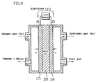
- the electrodes thus produced were disposed on both sides of a polymer electrolyte membrane (Nafion 112, manufactured by Du Pont) 10 and these were hot-pressed to produce a membrane electrode assembly, and then unit cells obtained were tested by preparing fuel cell measuring cells as shown in FIG. 11.
- numeral 20 is the polymer electrolyte membrane.
- numerals 24 and 25 are the anode and the cathode, respectively.
- the addition amount of the polymer electrolyte was 1.0 mg/cm 2 per apparent electrode surface, and equal characteristics were obtained in the range of 0.1 to 3.0 mg/cm 2 . Also, the addition amount of platinum was made 0.5 mg/cm 2 per electrode surface in the same manner.
- Unit cells produced according to the methods of Examples 9 and 11 and Comparative Example 1 were named A, B and X, respectively. Also, a unit cell using a catalytic reaction layer prepared by mixing the catalyst powder treated as in Example 9 and the carbon carrier treated as in Example 10 was named C.
- FIG. 12 shows the current-voltage characteristics of the cells A, B, C and X according to the examples and Comparative Example 1 of the present invention.
- Table 3 shows the current density characteristics when the cell voltage was 850 mV, which is a reaction rate-determining region, and the cell voltages when the current density of the cells was 1000 A/cm 2 .
- the current density at the cell voltage of 850 mV was 9 mA/cm 2 in the cell X of the Comparative Example 1, whereas in the cells A, B and C using the electrodes of this example maintained a current density of 48, 50 and 50 mA/cm 2 , respectively, which were excellent characteristics of more than 5 times of the comparative example.
- the reason for this is considered that the electrodes of the present invention have a reaction surface area of more than 5 times of the electrodes of the comparative example.
- a monomolecular layer of a polymer having a film thickness of about 1 to 100 nm could be formed. Since the monomolecular size was sufficiently small, the catalyst inside the micropores which polymer electrolyte molecules of several hundred nm order such as "Nafion solution" could not adsorb could be coated, and a hydrogen ion channel was formed in the catalyst inside the micropores and could contribute to the reaction, and as a result, high current density could be obtained.
- the cell voltage at the current density of 1000 mA/cm 2 was 0.29 V in the cell C of the comparative Example, whereas the cells A, B and C could maintain higher values of 0.55, 0.64 and 0.66, respectively.
- the reason for this is considered that since the electrodes of the present invention have a large reaction surface area, as mentioned above, higher characteristics could be obtained even when the cell was operated at a high current density as compared to the comparative example.
- the hydrogen ion conductive monomolecular layer itself contains a fluorine in a part of the hydrocarbon chain, which permitted improved gas solubility and improved gas supply ability to the catalyst and thereby the characteristics in the high current density region were improved.
- a catalytic reaction layer was formed by mixing the catalyst powder with adsorbed thereon a hydrogen ion conductive monomolecular layer treated as in Example 9 and the carbon carrier with adsorbed thereon a monomolecular layer containing a fluorine in a part of the linear hydrocarbon chain according to Example 10, which is considered to have further increased the gas supply ability in the catalyst layer thereby to improve the characteristics in the high current density region.
- FIG. 14 shows, on the surface of carbon particles 92 carrying 20% by weight of catalyst particles 91 comprising platinum in the form of particle having a diameter of around 1 to 10 nm, a silane compound was adsorbed directly by chemical adsorption under a nitrogen gas atmosphere and a monomolecular protection film comprising the silane compound was formed.
- a silane compound was adsorbed directly by chemical adsorption under a nitrogen gas atmosphere and a monomolecular protection film comprising the silane compound was formed.
- CH 3 -(CH 2 )n-Si(OCH 3 ) 3 (n is an integer of 2 to 10) having a linear hydrocarbon chain was used as the silane compound, an ethanol solution dissolving the same at a concentration of 1% by weight was prepared, into which the above-mentioned platinum particle carrying carbon powder was immersed, and this was heated at 60 °C for one hour.
- a natural oxidized film which contains -OH group and oxide.
- the carbon powder 92 used was a carbon powder with surface functional group such as phenolic hydroxyl group, carboxyl group, lactone group, carbonyl group, quinone group, or anhydride carboxylic acid group are present on the surface thereof.
- a monomolecular adsorption film 93 of a silane compound was formed to have a thickness of around 2 to 10 nm on the surface of the catalyst metal 91 and the surface of the carbon carrier 92. Also, it could be formed to have a thickness of about 1 to 100 nm by changing the molecular amount of the monomolecular.
- the material for chemical adsorption is not restricted to the silane compound used above as long as it contains group capable of bonding with -OH group or oxide, for example, ⁇ Si(OCH 3 ), ⁇ Si(OC 2 H 5 ) groups and the like.
- silane compounds having amid group or amine group as the basic functional group containing a nitrogen atom having a lone pair such as Si(OCH 3 ) 3 -(CH 2 )n-NH 2 (n is an integer of 2 to 10), Si(OCH 3 ) 3 -(CH 2 )m-NH-(CH 2 )n-NH 2 (m and n are integers of 2 to 10), Si(OCH 3 ) 3 -(CH 2 )n-(C 6 H 4 )-NH 2 (n is an integer of 2 to 10), Si(OCH 3 ) 3 -(CH 2 )m-N(CH 3 ) 2 (m is an integer of 2 to 10), Si(OCH 3 ) 3 -(CH 2 )n-(C 6 H 4 )-N(CH 3 ) 2 (n is an integer of 2 to 10), Si(OC 2 H 5 ) 3 -(CH 2 )n-N(CH 2 CH 2 OH) 2 (CH 2 )n (n (n (n
- Si(OCH 3 ) 3 -(CH 2 )n-(CF 2 )m-NH 2 (n and m are integers of 2 to 10)
- Si(OCH 3 ) 3 -(CH 2 )m-NH-(CH 2 )n-(CF 2 )l-NH 2 (m, n and l are integers of 2 to 7)
- Si(OCH 3 ) 3 -(CH 2 )n-(CF 2 )m-(C 6 H 4 )-NH 2 (n and m are integers of 2 to 7)
- Si(OCH 3 ) 3 -(CH 2 )n-(CF 2 )m-(C 6 H 4 )-NH 2 (n and m are integers of 2 to 7)
- Electrode catalyst powders described in Examples 12 and 13 and Comparative Example 2 above were applied onto carbon papers (TGP-H-120, manufactured by Toray Industries, Inc., film thickness 360 ⁇ m) serving as the gas diffusion layers to form the catalytic reaction layers, thereby obtaining the electrodes.
- carbon papers TGP-H-120, manufactured by Toray Industries, Inc., film thickness 360 ⁇ m
- the electrodes thus produced were disposed on both sides of a polymer electrolyte membrane (Nafion 112, manufactured by Du Pont) 20, and these were subjected to hot-pressing and thereby a membrane electrode assembly was produced.
- a polymer electrolyte membrane Nafion 112, manufactured by Du Pont
- tests were conducted by preparing fuel cell measurement cells as shown in FIG. 10.
- Discharge tests of the cells were carried out by supplying hydrogen gas to the anode 24 and air to the cathode 25 of these unit cells and adjusting the cell temperature to 75 °C, the fuel utilization rate to 80%, the air utilization rate to 30% and the gas humidification so that the hydrogen gas and the air had their dew points of 75 °C and 65 °C, respectively.
- Cells produced by using the electrodes prepared in Examples 12 and 13 and Comparative Example 2 were called respectively D (hydrocarbon chain type), E (fluorocarbon chain type), and Y (non surface-treated type).
- FIG. 15 shows the current-voltage characteristics of the cells D, E and Y according to the examples and the comparative example of the present invention. Further, Table 4 shows cell voltages when the operation current density of the cell were made 300 mA/cm 2 , which was a low current density, and also 700 mA/cm 2 , which was a high current density.
- the cells D and E have further improved characteristics than the cell Y despite that the amounts of polymer electrolyte and platinum catalyst contained in the electrodes are about the same, and the reason for this is considered that the silane compound having a basic functional group covered the catalyst carrier surface and formed a monomolecular layer, and this monomolecular layer further formed a minute polymer electrolyte layer in the vicinity of the catalyst carrier, which enabled further efficient hydrogen ion exchange.
- the carbon powder serving as the catalyst carrier was subjected to surface treatment, however the constitution of the present invention can be used for the catalyst metal itself as long as it is a catalyst metal containing -OH group or oxide on the surface.
- a fourth embodiment of the present invention has characteristics in electrodes in a fuel cell. That is to say, the fourth embodiment is a fuel cell, comprising an membrane electrode assembly formed by laminating a hydrogen ion conductive polymer electrolyte membrane, a pair of electrodes sandwiching the above hydrogen ion conductive polymer electrolyte membrane and a pair of diffusion layers sandwiching the above electrodes, wherein the above electrodes include at least a catalyst comprising a hydrophilic carbon material with catalyst particles carried thereon, a hydrogen ion conductive polymer electrolyte and a water repellent carbon material.
- a hydrophilic layer is chemically bonded to at least a part of the catalyst particle surface.
- the catalyst comprising a hydrophilic carbon material with catalyst particles carried thereon is selectively disposed on the hydrogen ion conductive polymer electrolyte membrane side, and the water repellent carbon material is selectively disposed on the gas diffusion layer side.
- the water repellent carbon material comprises a monomolecular layer formed by chemically bonding a silane coupling agent having a hydrophobic portion to a part of or entire surface of the carbon material.
- the hydrophilic carbon material comprises a layer formed by chemically bonding a silane coupling agent having a hydrophilic portion to a part of or entire surface of the carbon material.
- the above carbon material is chemically bonded to the silane coupling agent through the intermediary of at least one functional group selected from among phenolic hydroxyl group, carboxyl group, lactone group, carbonyl group, quinone group, and anhydride carboxylic acid group.
- the present invention also relates to a production method of the above-mentioned electrodes. That is to say, the above electrodes can be produced by immersing at least one kind of catalyst particles or carbon material in a solvent containing a silane coupling agent thereby making the silane coupling agent chemically adsorbed onto at least a part of the catalyst particle surface or the carbon material surface, and subsequently chemically bonding the silicon atom in a molecule of the silane coupling agent to the catalyst particle surface or the carbon material surface.
- the catalytic reaction layer is constituted by a polymer electrolyte, a hydrophilic carbon material and a water repellent material, water is adequately retained by the hydrophilic carbon material in the vicinity of the three phase zone where the electrode reaction occurs, and water generated in excess is promptly discharged by the adjacent water repellent carbon material.
- the electrodes retain a certain water retention capacity because of the hydrophilic carbon material, and thus high characteristics can be expected.
- excess generated water is promptly discharged by the water repellent carbon material disposed in the very vicinity of the hydrophilic carbon material, therefore flooding phenomenon does not readily occur, and thus the cell performance is improved.
- the polymer electrolyte membrane side is under higher-humidified atmosphere, which improves ion conductivity of the polymer electrolyte membrane and improves the cell characteristics.
- hydrolyzable group of the silane coupling agent having a hydrophobic portion is hydrolyzed on the surface of the carbon particles by water in the solvent or in the air, or water adsorbed on the carbon surface. It is, then, converted into active silanol group ( ⁇ SiOH), and reacts with functional group on the carbon surface to form a strong bond. As a consequence, a microscopic monomolecular water repellent layer of several nm to several tens of nm is formed on the carbon particle surface.
- hydrolyzable group of the silane coupling agent is hydrolyzed by water in the solvent or in the air, or water adsorbed onto the carbon surface in the same manner as previously. Then, it is converted into active silanol group ( ⁇ SiOH) and reacts with functional group on the carbon surface to form a strong bond.
- this silane coupling agent contain a hydrophilic group such as sulfonic acid group, carboxyl group and the like, the catalyst surface is made hydrophilic and the moist condition around the three-phase zone is maintained.
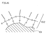
- a monomolecular layer comprising a silane coupling agent was formed by making the entire surface of the carbon powder adsorb directly a silane coupling agent by chemical adsorption under a nitrogen gas atmosphere.
- a silane coupling agent CH 3 -(CH 2 )n-SiCl 3 (n is an integer of 10 to 25) which contains a linear hydrocarbon chain was used, and a hexane solvent dissolving the same at 1% by weight was prepared and the above carbon particles were immersed therein.
- the carbon particles used at this time were a graphitizable carbon with a phenolic hydroxyl group and a carboxyl group remaining on the surface thereof, and a monomolecular water repellent layer comprising the silane coupling agent was formed by subjecting these functional groups and -SiCl 3 of the silane coupling agent to hydrochloric acid elimination reaction.
- FIG. 16 shows this state.
- 101 is a carbon particle and 102 is a monomolecular water repellent layer.
- the thickness of the monomolecular water repellent layer 102 was about 2 to 10 nm.
- the membrane thickness of the same could be made 1 to 100 nm.
- the material for chemical adsorption it is not restricted to the silane base surfactant used in this example as long as it contains group capable of bonding with -OH group such as ⁇ SiCl group and the like.
- a hydrophilic carbon powder with platinum carried thereon at 25% by weight, which serves as an electrode catalyst, and the above water repellent carbon material were mixed, to which a solution dispersing a polyfluorocarbon type polymer electrolyte containing pendant -SO 3 H group(FSS-1, manufactured by Asahi Grass Co., Ltd.) and butanol were added to prepare an ink.
- a solution dispersing a polyfluorocarbon type polymer electrolyte containing pendant -SO 3 H group(FSS-1, manufactured by Asahi Grass Co., Ltd.) and butanol were added to prepare an ink.
- a carbon paper TGP-H-120, manufactured by Toray Industries, Inc., film thickness of 360 ⁇ m
- the platinum carrying carbon powder used was a hydrophilic one having many surface functional groups (VulcanXC72R, manufactured by Cabot). Also, the platinum amount per unit area was made 0.5 mg/cm 2 . Further, the mixing ratio of the platinum carrying hydrophilic carbon powder, water repellent carbon material and polyfluorocarbon type polymer electrolyte was 100:20:3 after preparation.
- the electrode B' for comparison was one produced by forming a noble metal carrying carbon powder serving as the catalyst and a water repellent agent on a porous electroconductive electrode supporting material serving as the gas diffusion layer, as a conventionally proposed constitution.
- the porous electroconductive electrode material the same carbon paper used for the electrode A' above (TGP-H-120, manufactured by Toray Industries, Inc., film thickness of 360 ⁇ m) was used, and this was primarily subjected to water repellency treatment by using a solution dispersing a polyfluorocarbon type polymer electrolyte containing pendant -SO 3 H group (FSS-1, manufactured by Asahi Glass Co., Ltd.).
- the carbon powder used was a water repellent one having a few surface functional groups (Denka Black, manufactured by DENKI KAGAKU KOGYO KABUSHIKI KAISHA). Also, as the water repellency agent, a solution dispersing a polyfluorocarbon type polymer electrolyte containing pendant -SO 3 H group (FSS-1, manufactured by Asahi Glass Co., Ltd.) was used. Apart from this, the constitution was made the same as the electrode A' above.
- the respective electrode A' of this example thus produced and the electrode B' of the comparative example were disposed on both sides of respective polymer electrolyte membranes (Nafion 112, manufactured by Du Pont), and these were hot-pressed to produce membrane electrode assemblies. These were set in unit cell measuring devices as shown in FIG. 11 to configure unit cells.
- numerals 20, 24 and 25 denote the membrane electrode assembly mentioned above.
- electrodes were produced by placing the catalytic reaction layer on the polymer electrolyte side and the water repellent carbon particles on the gas diffusion layer side, and the characteristics thereof were evaluated.
- the catalyst carrying carbon powder and the water repellent carbon powder treated with the silane coupling agent as shown in Example 14 were prepared into separate inks and were applied to form the electrodes. This is shown in FIG. 18.
- a water repellent carbon powder (Denka Black, manufactured by DENKI KAGAKU KOGYO KABUSHIKI KAISHA) was prepared into an ink using butanol, and this was screen-printed on a carbon paper ( TGP-H-120, manufactured by Toray Industries, Inc., film thickness of 360 ⁇ m).
- a catalyst carrying carbon powder 106 was prepared into an ink by using a solution dispersing a polyfluorocarbon type polymer electrolyte with pendant -SO 3 H group (FSS-1, manufactured by Asahi Glass Co., Ltd.) and butanol, and this ink was applied onto the above carbon paper 108 coated with the above water repellent carbon powder 107 by the screen printing process, thereby producing electrodes.
- FSS-1 polyfluorocarbon type polymer electrolyte with pendant -SO 3 H group
- Example 15 710 Electrode A' 690 Electrode B' 620
- Example 15 From Table 5, it is found that, by using the electrodes with the electrode catalyst layer disposed on the polymer electrolyte membrane side and the water repellent carbon particles disposed on the gas diffusion layer side, as employed in Example 15, the equal characteristics can be obtained as the one using the carbon powder treated with a silane coupling agent in Example 14. From this, it is found that a cell with further excellent characteristics can be configured by using electrodes with an electrode catalyst layer disposed on the polymer electrolyte membrane side and a water repellent carbon particles on the gas diffusion layer side.
- the catalyst carrying carbon powder was treated with a silane coupling agent was described referring to FIG. 19.
- a silane coupling agent used in Example 14 and ClSO 2 -(CH 2 )n-(CF 2 )m-SiCl 3 (n and m are integers of 10 to 25) having a hydrocarbon chain and a fluorocarbon chain in the main chain and having sulfonic acid group at the end in place of the silane coupling agent used in Example 14, a monomolecular film 110 having sulfonic acid group on the respective surfaces of platinum particles 109 and carbon particles 101 was formed.
- This monomolecular layer is hydrophilic because of having sulfonic acid group at the end.
- the silane coupling agent is not restricted to the silane base surfactant as described in the example as long as it contains a hydrophilic portion.
- Electrodes were prepared in the same manner as in Example 14 and a unit cell as shown in FIG. 11 was produced by using the same.
- Example 14 When the characteristics of the cell were evaluated under the same conditions as in Example 14, the voltage at the current density of 700 mA/cm 2 was 720 mV. This is a higher characteristic than the cell prepared in Example 14, and the reason for this is considered that wet property around the three phase zone was improved by subjecting the catalyst fine particle carrying carbon powder to water repellency treatment with the silane coupling agent.
- a chlorosilane type surfactant having sulfonic acid group was used as the silane coupling agent, however any type of agents, as long as they have a hydrophilic portion, for example those having carboxyl group and the like, can be used.
- both of the catalyst fine particles and the carbon particles were treated, however only one of them may be treated as long as they are applicable in the present invention.
- the carbon powder and the catalyst carrying carbon powder used are not restricted to the ones used in this example as long as they are applicable in the present invention.
- a layer comprising electroconductive fine particles is disposed between the catalytic reaction layer and the gas diffusion layer, which decreases the contact resistance between the catalytic reaction layer and the gas diffusion layer, thereby improving the cell characteristics. Also, if the layer comprising electroconductive fine particles penetrates partially into the gas diffusion layer, the effect thereby is further improved. Further, since the catalytic reaction layer never penetrates into the gas diffusion layer, the amount used of the noble metal catalyst for use in the catalytic reaction layer can be reduced more than conventionally, and thus a cost reduction effect can be expected.
- the electrodes for fuel cell according to the third embodiment of the present invention are characterized in that the surface of the catalyst particles or catalyst carrier has hydrogen ion diffusion function, and has a functional polymer adsorbed thereon.
- a monomolecular polymer electrolyte layer can be uniformly adsorbed on the catalyst metal surface or the carbon surface with catalyst carried thereon, and a hydrogen ion channel can be formed in the catalyst inside the micropores.
- the reaction surface area is enlarged, which permits realization of a polymer electrolyte fuel cell exhibiting a higher discharge performance.
- the hydrophilicity of this polymer layer can be increased by making a silane compound have a hydrocarbon chain, and thus the electrodes can maintain a certain water retention capacity and high performance can be obtained even when the fuel cell is operated at a low current density and little water generates, or the fuel cell is operated in a low-humidified air.
- the water repellency of the polymer layer can be increased by making it have a fluorocarbon chain, and the gas diffusion ability of the electrodes can be improved and a high performance can be obtained even when the fuel cell is operated at a high current density and a large quantity of water generates, or when the fuel cell is operated in high-humidified air.
- the electrodes of the present invention are characterized in that functional polymer having hydrogen ion diffusion function is adsorbed on the surface of the catalyst particles or the catalyst carrier.
- This functional polymer functions as a polymer electrolyte layer.
- a silane compound having basic functional group is used to form this, and a monomolecular layer is formed as the functional polymer.
- a minute polymer electrolyte layer is formed close to the catalyst, and efficient hydrogen ion channel and a gas channel are formed.
- a polymer electrolyte fuel cell exhibiting a high discharge performance can be realized.
- the noble metal catalyst amount used for the catalytic reaction layer can be reduced without deteriorating the discharge characteristics, and thereby a cost reduction is made possible.
- the electrode catalyst that is the most suitable for the operation conditions of the fuel cell can be prepared.
- the catalytic reaction layer is constituted by a polymer electrolyte, hydrophilic catalyst carrying carbon particles and water repellent carbon particles, appropriate moisture condition is maintained by the hydrophilic catalyst carrying carbon particles around the three-phase zone where the electrode reaction occurs, and water generated in excess is promptly discharged by the adjacent water repellent carbon.
- the polymer electrolyte membrane side is under highly humidified atmosphere, which improves ion conductivity of the polymer electrolyte membrane to improve the cell characteristics.
- a hydrolyzable group of the silane coupling agent having a hydrophobic portion is hydrolyzed by water in the solution or in the air or water adsorbed on the carbon surface, and it is converted into an active silanol group ( ⁇ SiOH) and reacts with functional group on the carbon surface to form a strong bond.
- ⁇ SiOH active silanol group
- hydrolyzable group of the silane coupling agent is hydrolyzed, in the same manner as above, by water in the solution or in the air or water adsorbed on the carbon surface, and it is converted into active silanol group ( ⁇ SiOH) and reacts with functional group on the carbon surface to form a strong bond.
- this silane coupling agent have a hydrophilic group such as sulfonic acid group, carboxyl group or the like, the catalyst surface is rendered hydrophilic, and thereby moisture condition around the three-phase zone is maintained.
- the polymer electrolyte fuel cell of the present invention exhibits an excellent performance with an efficient electrode reaction; by providing a layer comprising an electroconductive fine particle between the catalytic reaction layer and the gas diffusion layer in the electrodes; by providing a hydrogen ion diffusion layer on at least either surface of the catalyst particle or the carrier, which carries the catalyst particle in the catalytic reaction layer; or by constituting the catalytic reaction layer with at least a catalyst comprising a hydrophilic carbon material with catalyst particles carried thereon and a water repellent carbon material.
Landscapes
- Chemical & Material Sciences (AREA)
- Chemical Kinetics & Catalysis (AREA)
- Electrochemistry (AREA)
- General Chemical & Material Sciences (AREA)
- Engineering & Computer Science (AREA)
- Life Sciences & Earth Sciences (AREA)
- Manufacturing & Machinery (AREA)
- Sustainable Development (AREA)
- Sustainable Energy (AREA)
- Materials Engineering (AREA)
- Fuel Cell (AREA)
- Inert Electrodes (AREA)
Abstract
Description
| Average primary particle diameter (nm) | Cell voltage (V) |
| 5 | 0.59 |
| 10 | 0.63 |
| 50 | 0.64 |
| 100 | 0.63 |
| 500 | 0.58 |
| PTFE amount (% by weight) | Cell voltage (V) |
| 1 | 0.63 |
| 5 | 0.66 |
| 10 | 0.67 |
| 25 | 0.68 |
| 50 | 0.68 |
| 75 | 0.67 |
| 80 | 0.57 |
| Cell | Current density (mA/cm2) | Voltage (V) |
| A | 48 | 0.55 |
| B | 50 | 0.64 |
| C | 50 | 0.66 |
| X | 9 | 0.29 |
| Cell | Cell voltage (mV) | |
| I=300mA/cm2 | i=700mA/cm2 | |
| D | 770 | 670 |
| E | 750 | 690 |
| | 700 | 600 |
| Cell voltage (mV) | |
| Example 15 | 710 |
| Electrode A' | 690 |
| Electrode B' | 620 |
Claims (20)
- A polymer electrolyte fuel cell comprising a polymer electrolyte membrane and a pair of electrodes having each a catalytic reaction layer and a gas diffusion layer, said polymer electrolyte membrane being disposed between the pair of electrodes,
wherein a part of a carrier, which carries a catalyst particle, in said catalytic reaction layer penetrates into the inside of said polymer electrolyte membrane. - The polymer electrolyte fuel cell in accordance with claim 1, wherein said carrier is needle-shaped carbon fiber.
- A polymer electrolyte fuel cell comprising a polymer electrolyte membrane and a pair of electrodes having each a catalytic reaction layer and a gas diffusion layer, said polymer electrolyte membrane being sandwiched by the pair of electrodes,
wherein said fuel cell further comprises a layer comprising an electroconductive fine particle between said catalytic reaction layer and the gas diffusion layer. - The polymer electrolyte fuel cell in accordance with claim 3, wherein a part of said layer comprising an electroconductive fine particle penetrates into said gas diffusion layer.
- The polymer electrolyte fuel cell in accordance with claim 3 or 4, wherein materials for electroconductive particles, which constitute said layer comprising an electroconductive fine particle, are different on respective sides of the polymer electrolyte membrane.
- The polymer electrolyte fuel cell in accordance with claim 3, wherein said electroconductive fine particle is carbon powder with PTFE adhered thereto.
- A polymer electrolyte fuel cell comprising a polymer electrolyte membrane and a pair of electrodes each having a catalytic reaction layer and a gas diffusion layer, said polymer electrolyte membrane being disposed between the pair of electrodes,
wherein a hydrogen ion diffusion layer is provided on at least either surface of a catalyst particle or a carrier, which carries the catalyst particle in said catalytic reaction layer. - The polymer electrolyte fuel cell in accordance with claim 7, wherein said hydrogen ion diffusion layer is formed by chemically bonding a silane compound onto at least either surface of said catalyst particle or said carrier, which carries the catalyst particle;
- The polymer electrolyte fuel cell in accordance with claim 7, wherein said hydrogen ion diffusion layer comprises an organic compound having a basic functional group and a hydrogen ion conductive electrolyte, and said organic compound modifies at least either surface of the catalyst particle or the carrier, which carries the catalyst particle.
- The polymer electrolyte fuel cell in accordance with claim 7, wherein said basic functional group contains a nitrogen atom having a lone pair.
- The polymer electrolyte fuel cell in accordance with claim 9, wherein said organic compound having a basic functional group is a silane compound.
- The polymer electrolyte fuel cell in accordance with claim 8 or 11, wherein said silane compound has a functional group capable of dissociating a hydrogen ion.
- The polymer electrolyte fuel cell in accordance with claim 8, 11 or 12, wherein said silane compound has at least either a hydrocarbon chain or a fluorocarbon chain.
- The polymer electrolyte fuel cell in accordance with any of claims 11 to 14, wherein said silane compound is chemically bonded to at least either surface of the catalyst particle or the carrier, which carries the catalyst particle, through the intermediary of at least one kind of functional group selected from the group consisting of phenolic hydroxyl group, carboxyl group, lactone group, carbonyl group, quinone group and anhydride carboxylic acid group.
- A polymer electrolyte fuel cell comprising a polymer electrolyte membrane and a pair of electrodes each having a catalytic reaction layer and a gas diffusion layer, said polymer electrolyte membrane being disposed between the pair of electrodes,
wherein said catalytic reaction layer contains at least a water repellent carbon material and a catalyst body comprising a hydrophilic carbon material with a catalyst particle carried thereon. - The polymer electrolyte fuel cell in accordance with claim 15, wherein a hydrophilic layer is chemically bonded to at least a part of the catalyst particle surface.
- The polymer electrolyte fuel cell in accordance with claim 15 or 16, wherein said catalyst is selectively disposed on the polymer electrolyte membrane side and the water repellent carbon material is disposed on the gas diffusion layer side in said catalytic reaction layer.
- The polymer electrolyte fuel cell in accordance with claim 15 or 16, wherein said water repellent carbon material has a monomolecular layer formed by chemically bonding a silane compound having a hydrophobic portion to at least a part of the carbon material surface.
- The polymer electrolyte fuel cell in accordance with claim 15 or 16, wherein said hydrophilic carbon material has a monomolecular layer formed by chemically bonding a silane compound having a hydrophilic portion to at least a part of the carbon material surface.
- The polymer electrolyte fuel cell in accordance with claim 18 or 19, wherein said silane compound is chemically bonded to the carbon material surface through the intermediary of at least one kind of functional group selected from the group consisting of phenolic hydroxyl group, carboxyl group, lactone group, carbonyl group, quinone group and anhydride carboxylic acid group.
Applications Claiming Priority (9)
| Application Number | Priority Date | Filing Date | Title |
|---|---|---|---|
| JP10168174A JP2000003714A (en) | 1998-06-16 | 1998-06-16 | Polymer electrolyte fuel cell and method of manufacturing the same |
| JP16817498 | 1998-06-16 | ||
| JP29034098A JP3444530B2 (en) | 1998-10-13 | 1998-10-13 | Fuel cell |
| JP29034098 | 1998-10-13 | ||
| JP02824599A JP3992866B2 (en) | 1999-02-05 | 1999-02-05 | FUEL CELL ELECTRODE AND METHOD FOR PRODUCING THE SAME |
| JP2824599 | 1999-02-05 | ||
| JP4118499 | 1999-02-19 | ||
| JP04118499A JP3565077B2 (en) | 1999-02-19 | 1999-02-19 | Electrode for fuel cell and method for producing the same |
| PCT/JP1999/003123 WO1999066578A1 (en) | 1998-06-16 | 1999-06-10 | Polymer electrolyte fuel cell |
Publications (2)
| Publication Number | Publication Date |
|---|---|
| EP1096587A1 true EP1096587A1 (en) | 2001-05-02 |
| EP1096587A4 EP1096587A4 (en) | 2009-03-04 |
Family
ID=27458841
Family Applications (1)
| Application Number | Title | Priority Date | Filing Date |
|---|---|---|---|
| EP99925304A Withdrawn EP1096587A4 (en) | 1998-06-16 | 1999-06-10 | FUEL CELL COMPRISING A POLYMER ELECTROLYTE |
Country Status (5)
| Country | Link |
|---|---|
| US (2) | US6746793B1 (en) |
| EP (1) | EP1096587A4 (en) |
| KR (1) | KR100413645B1 (en) |
| CN (3) | CN1516311A (en) |
| WO (1) | WO1999066578A1 (en) |
Cited By (15)
| Publication number | Priority date | Publication date | Assignee | Title |
|---|---|---|---|---|
| FR2826781A1 (en) * | 2001-06-29 | 2003-01-03 | Commissariat Energie Atomique | BILOUS DIFFUSER FUEL CELL ASSEMBLY AND CREATION METHOD |
| WO2002039533A3 (en) * | 2000-11-09 | 2003-02-27 | Ird As | Membrane electrode assemblies for direct methanol fuel cells and methods for their production |
| WO2003047015A3 (en) * | 2001-11-28 | 2004-02-26 | 3M Innovative Properties Co | Fuel cell gas diffusion layer coating process and treated article |
| WO2002084767A3 (en) * | 2001-04-11 | 2005-06-16 | Cabot Corp | Fuel cells and other products containing modified carbon products |
| EP1298747A3 (en) * | 2001-09-27 | 2005-12-21 | Honda Giken Kogyo Kabushiki Kaisha | Method and apparatus for producing fuel cell electrodes |
| EP1318559A3 (en) * | 2001-12-04 | 2006-02-08 | Umicore AG & Co. KG | Method for the production of membrane electrode assemblies for fuel cells |
| EP1349224A4 (en) * | 2000-12-05 | 2007-05-16 | Matsushita Electric Industrial Co Ltd | POLYELECTROLYTE FUEL CELL AND METHOD OF OPERATING IT |
| EP1383184A4 (en) * | 2001-04-27 | 2008-04-16 | Matsushita Electric Industrial Co Ltd | ELECTRODE FOR FUEL CELL AND METHOD FOR MANUFACTURING THE ELECTRODE |
| US7662505B2 (en) | 2002-10-31 | 2010-02-16 | Panasonic Corporation | Porous electrode, and electrochemical element made using the same |
| EP1427041A3 (en) * | 2002-11-29 | 2011-03-09 | Honda Motor Co., Ltd. | Optimized catalyst coverage for solid polymer electrolyte membrane fuel cell electrodes |
| EP2357043A3 (en) * | 2003-07-09 | 2011-10-05 | Maxwell Technologies, Inc. | Electrode and process for manufacturing such electrode |
| EP1879249A4 (en) * | 2005-04-28 | 2012-03-28 | Canon Kk | Hydrophobic catalyst layer for solid polymer fuel cell, method for producing same, solid polymer fuel cell and method for manufacturing same |
| US8213156B2 (en) | 2003-07-09 | 2012-07-03 | Maxwell Technologies, Inc. | Particle based electrodes and methods of making same |
| US8815443B2 (en) | 2003-07-09 | 2014-08-26 | Maxwell Technologies, Inc. | Dry-particle based adhesive and dry film and methods of making same |
| DE112005001131B4 (en) | 2004-05-20 | 2018-05-17 | General Motors Corp. | A fuel cell assembly |
Families Citing this family (37)
| Publication number | Priority date | Publication date | Assignee | Title |
|---|---|---|---|---|
| US6916575B2 (en) | 2001-03-08 | 2005-07-12 | Matsushita Electric Industrial Co., Ltd. | Polymer electrolyte type fuel cell |
| US20030022055A1 (en) * | 2001-04-11 | 2003-01-30 | Jameel Menashi | Fuel cells and other products containing modified carbon products |
| TW589760B (en) * | 2001-08-09 | 2004-06-01 | Sumitomo Chemical Co | Polymer electrolyte composition and fuel cell |
| US7569302B2 (en) * | 2002-11-05 | 2009-08-04 | Panasonic Corporation | Fuel cell for generating electric power |
| CN100530442C (en) * | 2003-04-28 | 2009-08-19 | 旭硝子株式会社 | Solid polymer electrolyte material, production method thereof and membrane electrode assembly for solid polymer electrolyte fuel cell |
| JP4293831B2 (en) * | 2003-05-16 | 2009-07-08 | 三洋電機株式会社 | Fuel cell |
| US7306874B2 (en) * | 2003-11-20 | 2007-12-11 | General Motors Corporation | PEM fuel cell stack with coated flow distribution network |
| US7396611B2 (en) * | 2003-12-15 | 2008-07-08 | Plug Power Inc. | Fuel cell catalyst layer |
| JP4304101B2 (en) * | 2003-12-24 | 2009-07-29 | 本田技研工業株式会社 | Electrolyte membrane / electrode structure and fuel cell |
| KR100599774B1 (en) * | 2004-06-07 | 2006-07-13 | 삼성에스디아이 주식회사 | Membrane / electrode assembly for fuel cell, manufacturing method thereof and fuel cell comprising same |
| EP1829147A2 (en) | 2004-11-16 | 2007-09-05 | Battelle Memorial Institute | Solution based enhancements of fuel cell components and other electrochemical systems and devices |
| JP5066916B2 (en) * | 2004-12-01 | 2012-11-07 | コニカミノルタホールディングス株式会社 | Fuel cell electrode catalyst, fuel cell electrode and fuel cell |
| FR2879823A1 (en) * | 2004-12-16 | 2006-06-23 | Sagem | Heterogeneous catalytic electrode comprises a diffusion layer, where the diffusion layer is associated with a catalytic layer comprising active catalyst particles |
| KR20070114219A (en) * | 2005-04-27 | 2007-11-29 | 가부시끼가이샤 도시바 | Catalyst Layer Electrode for Fuel Cell and Fuel Cell |
| KR100696621B1 (en) * | 2005-05-11 | 2007-03-19 | 삼성에스디아이 주식회사 | Electrode base material for fuel cell, manufacturing method thereof and membrane-electrode assembly comprising same |
| JP4749088B2 (en) * | 2005-08-26 | 2011-08-17 | 三洋電機株式会社 | Operation method of fuel cell power generator |
| TWI267219B (en) * | 2005-08-29 | 2006-11-21 | Ind Tech Res Inst | Composition, complex and method for enhancing catalysts utilization |
| WO2008026666A1 (en) * | 2006-08-28 | 2008-03-06 | Toyota Jidosha Kabushiki Kaisha | Reinforced electrolyte membrane for fuel cell, method for production thereof, membrane-electrode assembly for fuel cell, and solid polymer-type fuel cell having the assembly |
| JP4506740B2 (en) * | 2006-09-14 | 2010-07-21 | トヨタ自動車株式会社 | Catalyst structure for fuel cell, membrane electrode assembly, fuel cell, and method for producing catalyst structure for fuel cell |
| CN100527494C (en) * | 2006-09-15 | 2009-08-12 | 新源动力股份有限公司 | PTFE/C Composite Powder for Low Temperature Fuel Cell Electrode and Its Application |
| KR100759436B1 (en) * | 2006-11-20 | 2007-10-04 | 삼성에스디아이 주식회사 | Membrane-electrode assembly for fuel cell, manufacturing method thereof and fuel cell system comprising same |
| JP5105888B2 (en) * | 2007-02-01 | 2012-12-26 | キヤノン株式会社 | Gas diffusion electrode, fuel cell, and method of manufacturing gas diffusion electrode |
| US8026017B2 (en) | 2007-03-16 | 2011-09-27 | The United States Of America As Represented By The Secretary Of The Army | High voltage methanol fuel cell assembly using proton exchange membranes and base/acid electrolytes |
| US8304143B2 (en) * | 2008-11-25 | 2012-11-06 | GM Global Technology Operations LLC | Conductive and hydrophilic coating for PEMFC bipolar plate |
| WO2011030720A1 (en) | 2009-09-10 | 2011-03-17 | 日産自動車株式会社 | Method for manufacturing fuel cell gas diffusion layer, fuel cell gas diffusion layer, and fuel cell |
| JP4807536B2 (en) * | 2010-01-07 | 2011-11-02 | 独立行政法人日本原子力研究開発機構 | Hydrogen combustion catalyst, method for producing the same, and hydrogen combustion method |
| KR101309160B1 (en) * | 2011-08-11 | 2013-09-17 | 삼성에스디아이 주식회사 | Catalyst layer composition for fuel cell, and electrode for fuel cell, method of preparing electrode for fuel cell, membrane-electrode assembly for fuel cell, and fuel cell system using the same |
| CN102306807A (en) * | 2011-08-17 | 2012-01-04 | 华南理工大学 | Cathode of film-free air microbial fuel cell and manufacturing method thereof |
| JP5877494B2 (en) | 2011-08-25 | 2016-03-08 | 日産自動車株式会社 | Fuel cell electrode catalyst layer, fuel cell electrode, fuel cell membrane electrode assembly, and fuel cell |
| JP6003878B2 (en) * | 2013-12-25 | 2016-10-05 | トヨタ自動車株式会社 | Fuel cell system |
| CN105603718B (en) * | 2016-02-05 | 2019-02-19 | 济南圣泉集团股份有限公司 | A kind of composite fiber, its preparation method and use |
| KR102272379B1 (en) * | 2017-06-23 | 2021-07-02 | 코오롱인더스트리 주식회사 | Electrode with organic metal-oxide, method for manufacturing the same, membrane-electrode assembly comprising the same, and fuel cell comprising the membrane-electrode assembly |
| US20190027738A1 (en) * | 2017-07-18 | 2019-01-24 | Ph Matter, Llc | Multi-functional electrode additive |
| KR20210084646A (en) * | 2018-11-26 | 2021-07-07 | 더 보드 오브 트러스티스 오브 더 리랜드 스탠포드 쥬니어 유니버시티 | Method of Forming Catalyst Layer with Extended Surface Area and Catalyst Layer for Polymer Electrolyte Fuel Cell |
| JP7121912B2 (en) * | 2019-03-04 | 2022-08-19 | トヨタ自動車株式会社 | Negative electrode for non-aqueous lithium-ion secondary battery, and non-aqueous lithium-ion secondary battery using the same |
| CN111682186B (en) * | 2020-06-28 | 2021-09-17 | 蜂巢能源科技有限公司 | Silicon-carbon composite material, preparation method and application thereof |
| CN114335570B (en) * | 2021-12-22 | 2024-05-17 | 苏州大学 | Gas diffusion layer for fuel cell and preparation method and application thereof |
Family Cites Families (24)
| Publication number | Priority date | Publication date | Assignee | Title |
|---|---|---|---|---|
| JPS61295388A (en) | 1985-06-21 | 1986-12-26 | Japan Storage Battery Co Ltd | Production of ion exchange resin membrane-electrode joined body |
| JPS61295387A (en) | 1985-06-21 | 1986-12-26 | Japan Storage Battery Co Ltd | Production of ion exchange resin membrane-electrode joined body |
| ES2017622B3 (en) | 1985-12-09 | 1991-03-01 | Dow Chemical Co | AN IMPROVED SOLID POLYMER ELECTROLYTE ELECTRODE. |
| US4826554A (en) | 1985-12-09 | 1989-05-02 | The Dow Chemical Company | Method for making an improved solid polymer electrolyte electrode using a binder |
| JPH0665036B2 (en) | 1986-03-07 | 1994-08-22 | 田中貴金属工業株式会社 | Gas diffusion electrode and manufacturing method thereof |
| ZA876142B (en) | 1987-08-19 | 1989-02-20 | ||
| US4804592A (en) | 1987-10-16 | 1989-02-14 | The United States Of America As Represented By The United States Department Of Energy | Composite electrode for use in electrochemical cells |
| JPH01286256A (en) | 1988-05-12 | 1989-11-17 | Matsushita Electric Ind Co Ltd | Electrodes for fuel cells |
| JPH03184266A (en) | 1989-12-13 | 1991-08-12 | Toshiba Corp | Fuel cell with solid electrolyte |
| JPH03295172A (en) | 1990-04-13 | 1991-12-26 | Mitsubishi Heavy Ind Ltd | Junction body of solid polymer electrolyte film and electrode |
| JPH04264367A (en) | 1991-02-19 | 1992-09-21 | Fuji Electric Co Ltd | Solid macromolecule electrolyte type fuel cell |
| US5211984A (en) | 1991-02-19 | 1993-05-18 | The Regents Of The University Of California | Membrane catalyst layer for fuel cells |
| JPH0536418A (en) | 1991-03-13 | 1993-02-12 | Fuji Electric Co Ltd | Solid polymer electrolyte fuel cell and method of manufacturing the same |
| US5272017A (en) * | 1992-04-03 | 1993-12-21 | General Motors Corporation | Membrane-electrode assemblies for electrochemical cells |
| JP3100754B2 (en) * | 1992-05-20 | 2000-10-23 | 三菱電機株式会社 | Method for manufacturing electrochemical device using solid polymer electrolyte membrane |
| US5350643A (en) * | 1992-06-02 | 1994-09-27 | Hitachi, Ltd. | Solid polymer electrolyte type fuel cell |
| JP2842150B2 (en) | 1992-06-02 | 1998-12-24 | 株式会社日立製作所 | Polymer electrolyte fuel cell |
| US5460896A (en) | 1993-01-22 | 1995-10-24 | Kabushiki Kaisha Equos Research | Fuel cell |
| JPH07282814A (en) | 1994-04-01 | 1995-10-27 | Tanaka Kikinzoku Kogyo Kk | Method for manufacturing gas diffusion electrode |
| JP3549241B2 (en) | 1994-04-22 | 2004-08-04 | ジャパンゴアテックス株式会社 | Electrode for polymer solid electrolyte fuel cell and joined body thereof with polymer solid electrolyte |
| BE1008455A3 (en) | 1994-06-07 | 1996-05-07 | Vito | ELECTRODE GAS DIFFUSION WITH CATALYST FOR AN ELECTROCHEMICAL CELL WITH SOLID ELECTROLYTE AND METHOD FOR MANUFACTURING SUCH ELECTRODE. |
| JP3555196B2 (en) * | 1994-09-19 | 2004-08-18 | トヨタ自動車株式会社 | Fuel cell and method of manufacturing the same |
| JPH09245801A (en) | 1996-03-11 | 1997-09-19 | Tanaka Kikinzoku Kogyo Kk | Polymer solid oxide fuel cell electrode and method for producing the same |
| JPH09265992A (en) | 1996-03-29 | 1997-10-07 | Mazda Motor Corp | Fuel cell electrode structure |
-
1999
- 1999-06-10 CN CNA2003101239308A patent/CN1516311A/en active Pending
- 1999-06-10 CN CNB998074764A patent/CN1159788C/en not_active Expired - Fee Related
- 1999-06-10 CN CNA2003101239312A patent/CN1516312A/en active Pending
- 1999-06-10 EP EP99925304A patent/EP1096587A4/en not_active Withdrawn
- 1999-06-10 WO PCT/JP1999/003123 patent/WO1999066578A1/en not_active Ceased
- 1999-06-10 KR KR10-2000-7014308A patent/KR100413645B1/en not_active Expired - Fee Related
- 1999-06-10 US US09/719,664 patent/US6746793B1/en not_active Expired - Fee Related
-
2004
- 2004-03-10 US US10/797,676 patent/US20040170885A1/en not_active Abandoned
Cited By (19)
| Publication number | Priority date | Publication date | Assignee | Title |
|---|---|---|---|---|
| WO2002039533A3 (en) * | 2000-11-09 | 2003-02-27 | Ird As | Membrane electrode assemblies for direct methanol fuel cells and methods for their production |
| EP1349224A4 (en) * | 2000-12-05 | 2007-05-16 | Matsushita Electric Industrial Co Ltd | POLYELECTROLYTE FUEL CELL AND METHOD OF OPERATING IT |
| WO2002084767A3 (en) * | 2001-04-11 | 2005-06-16 | Cabot Corp | Fuel cells and other products containing modified carbon products |
| EP1383184A4 (en) * | 2001-04-27 | 2008-04-16 | Matsushita Electric Industrial Co Ltd | ELECTRODE FOR FUEL CELL AND METHOD FOR MANUFACTURING THE ELECTRODE |
| WO2003003490A3 (en) * | 2001-06-29 | 2004-01-22 | Commissariat Energie Atomique | Fuel cell assembly with a two-layer diffuser and production method of same |
| FR2826781A1 (en) * | 2001-06-29 | 2003-01-03 | Commissariat Energie Atomique | BILOUS DIFFUSER FUEL CELL ASSEMBLY AND CREATION METHOD |
| EP1298747A3 (en) * | 2001-09-27 | 2005-12-21 | Honda Giken Kogyo Kabushiki Kaisha | Method and apparatus for producing fuel cell electrodes |
| WO2003047015A3 (en) * | 2001-11-28 | 2004-02-26 | 3M Innovative Properties Co | Fuel cell gas diffusion layer coating process and treated article |
| EP1318559A3 (en) * | 2001-12-04 | 2006-02-08 | Umicore AG & Co. KG | Method for the production of membrane electrode assemblies for fuel cells |
| US7662505B2 (en) | 2002-10-31 | 2010-02-16 | Panasonic Corporation | Porous electrode, and electrochemical element made using the same |
| EP1427041A3 (en) * | 2002-11-29 | 2011-03-09 | Honda Motor Co., Ltd. | Optimized catalyst coverage for solid polymer electrolyte membrane fuel cell electrodes |
| EP2357043A3 (en) * | 2003-07-09 | 2011-10-05 | Maxwell Technologies, Inc. | Electrode and process for manufacturing such electrode |
| US8213156B2 (en) | 2003-07-09 | 2012-07-03 | Maxwell Technologies, Inc. | Particle based electrodes and methods of making same |
| US8815443B2 (en) | 2003-07-09 | 2014-08-26 | Maxwell Technologies, Inc. | Dry-particle based adhesive and dry film and methods of making same |
| US9525168B2 (en) | 2003-07-09 | 2016-12-20 | Maxwell Technologies, Inc. | Dry-particle based adhesive and dry film and methods of making same |
| US10547057B2 (en) | 2003-07-09 | 2020-01-28 | Maxwell Technologies, Inc. | Dry-particle based adhesive and dry film and methods of making same |
| DE112005001131B4 (en) | 2004-05-20 | 2018-05-17 | General Motors Corp. | A fuel cell assembly |
| EP1879249A4 (en) * | 2005-04-28 | 2012-03-28 | Canon Kk | Hydrophobic catalyst layer for solid polymer fuel cell, method for producing same, solid polymer fuel cell and method for manufacturing same |
| US8722220B2 (en) | 2005-04-28 | 2014-05-13 | Canon Kabushiki Kaisha | Hydrophobic catalyst layer for polymer electrolyte fuel cell and method of producing the same, and polymer electrolyte fuel cell and method of producing the same |
Also Published As
| Publication number | Publication date |
|---|---|
| CN1516312A (en) | 2004-07-28 |
| KR100413645B1 (en) | 2003-12-31 |
| EP1096587A4 (en) | 2009-03-04 |
| WO1999066578A1 (en) | 1999-12-23 |
| CN1516311A (en) | 2004-07-28 |
| US20040170885A1 (en) | 2004-09-02 |
| CN1305647A (en) | 2001-07-25 |
| KR20010074511A (en) | 2001-08-04 |
| US6746793B1 (en) | 2004-06-08 |
| CN1159788C (en) | 2004-07-28 |
Similar Documents
| Publication | Publication Date | Title |
|---|---|---|
| US6746793B1 (en) | Polymer electrolyte fuel cell | |
| EP1304753B1 (en) | Polyelectrolyte fuel cell | |
| JP4656683B2 (en) | Polymer electrolyte fuel cell | |
| EP1775788B1 (en) | Gas diffusion electrode and solid polymer electrolyte fuel cell | |
| EP1950826B1 (en) | Gas diffusion electrode substrate, gas diffusion electrode and process for its production, and fuel cell | |
| KR100421708B1 (en) | Fuel cell and method of menufacture thereof | |
| EP1601035A1 (en) | Polymer electrolyte fuel cell and method for producing the same | |
| JP3992866B2 (en) | FUEL CELL ELECTRODE AND METHOD FOR PRODUCING THE SAME | |
| JP3565077B2 (en) | Electrode for fuel cell and method for producing the same | |
| JP3444530B2 (en) | Fuel cell | |
| KR20070086110A (en) | Solution-based fuel cell components, electrochemical systems and devices | |
| JP2002289230A (en) | Polymer electrolyte fuel cell | |
| EP1298751A2 (en) | Polymer electrolyte fuel cell and production method thereof | |
| JP3459615B2 (en) | Electrode for fuel cell and fuel cell | |
| US6946214B2 (en) | Manufacturing method of fuel cell electrode and fuel cell using thereof | |
| JP2003109604A (en) | Gas diffusion electrode for fuel cell and method for producing the same | |
| KR102213590B1 (en) | Method for fabricating catalyst layer for high durability carbon-based fuel cell, catalyst layer for high durability carbon-based fuel cell fabricated by the method and membrane electrode assembly comprising the same | |
| JP2002063912A (en) | Method for manufacturing polymer electrolyte fuel cell | |
| JPH10334922A (en) | Polymer electrolyte fuel cell and method of manufacturing the polymer electrolyte fuel cell | |
| JP3962548B2 (en) | Polymer electrolyte fuel cell | |
| JP2001057217A (en) | Polymer electrolyte fuel cell | |
| JP2005228755A (en) | Polymer electrolyte fuel cell | |
| JP3433172B2 (en) | Polymer electrolyte fuel cell | |
| CN1985392B (en) | polymer electrolyte fuel cell | |
| JP2009009768A (en) | Manufacturing method of electrolyte membrane / electrode assembly and fuel cell |
Legal Events
| Date | Code | Title | Description |
|---|---|---|---|
| PUAI | Public reference made under article 153(3) epc to a published international application that has entered the european phase |
Free format text: ORIGINAL CODE: 0009012 |
|
| 17P | Request for examination filed |
Effective date: 20001213 |
|
| AK | Designated contracting states |
Kind code of ref document: A1 Designated state(s): DE FR GB IT |
|
| RIN1 | Information on inventor provided before grant (corrected) |
Inventor name: OHARA, HIDEO Inventor name: MORITA, JUNJI Inventor name: KANBARA, TERUHISA Inventor name: SUGAWARA, YASUSHI Inventor name: UCHIDA, MAKOTO Inventor name: HATOH, KAZUHITO Inventor name: YASUMOTO, EIICHI Inventor name: GYOTEN, HISAAKI |
|
| RAP1 | Party data changed (applicant data changed or rights of an application transferred) |
Owner name: PANASONIC CORPORATION |
|
| A4 | Supplementary search report drawn up and despatched |
Effective date: 20090129 |
|
| RIC1 | Information provided on ipc code assigned before grant |
Ipc: H01M 8/10 20060101ALI20090123BHEP Ipc: H01M 8/02 20060101ALI20090123BHEP Ipc: H01M 4/86 20060101AFI20090123BHEP |
|
| 17Q | First examination report despatched |
Effective date: 20110719 |
|
| STAA | Information on the status of an ep patent application or granted ep patent |
Free format text: STATUS: THE APPLICATION IS DEEMED TO BE WITHDRAWN |
|
| 18D | Application deemed to be withdrawn |
Effective date: 20130103 |