EP1775788B1 - Gas diffusion electrode and solid polymer electrolyte fuel cell - Google Patents
Gas diffusion electrode and solid polymer electrolyte fuel cell Download PDFInfo
- Publication number
- EP1775788B1 EP1775788B1 EP05753501.5A EP05753501A EP1775788B1 EP 1775788 B1 EP1775788 B1 EP 1775788B1 EP 05753501 A EP05753501 A EP 05753501A EP 1775788 B1 EP1775788 B1 EP 1775788B1
- Authority
- EP
- European Patent Office
- Prior art keywords
- gas diffusion
- water
- layer
- microporous
- electrode
- Prior art date
- Legal status (The legal status is an assumption and is not a legal conclusion. Google has not performed a legal analysis and makes no representation as to the accuracy of the status listed.)
- Expired - Fee Related
Links
Images


Classifications
-
- H—ELECTRICITY
- H01—ELECTRIC ELEMENTS
- H01M—PROCESSES OR MEANS, e.g. BATTERIES, FOR THE DIRECT CONVERSION OF CHEMICAL ENERGY INTO ELECTRICAL ENERGY
- H01M8/00—Fuel cells; Manufacture thereof
- H01M8/02—Details
- H01M8/0202—Collectors; Separators, e.g. bipolar separators; Interconnectors
- H01M8/023—Porous and characterised by the material
- H01M8/0239—Organic resins; Organic polymers
-
- H—ELECTRICITY
- H01—ELECTRIC ELEMENTS
- H01M—PROCESSES OR MEANS, e.g. BATTERIES, FOR THE DIRECT CONVERSION OF CHEMICAL ENERGY INTO ELECTRICAL ENERGY
- H01M4/00—Electrodes
- H01M4/86—Inert electrodes with catalytic activity, e.g. for fuel cells
- H01M4/8605—Porous electrodes
-
- H—ELECTRICITY
- H01—ELECTRIC ELEMENTS
- H01M—PROCESSES OR MEANS, e.g. BATTERIES, FOR THE DIRECT CONVERSION OF CHEMICAL ENERGY INTO ELECTRICAL ENERGY
- H01M4/00—Electrodes
- H01M4/86—Inert electrodes with catalytic activity, e.g. for fuel cells
- H01M4/8636—Inert electrodes with catalytic activity, e.g. for fuel cells with a gradient in another property than porosity
-
- H—ELECTRICITY
- H01—ELECTRIC ELEMENTS
- H01M—PROCESSES OR MEANS, e.g. BATTERIES, FOR THE DIRECT CONVERSION OF CHEMICAL ENERGY INTO ELECTRICAL ENERGY
- H01M4/00—Electrodes
- H01M4/86—Inert electrodes with catalytic activity, e.g. for fuel cells
- H01M4/8647—Inert electrodes with catalytic activity, e.g. for fuel cells consisting of more than one material, e.g. consisting of composites
- H01M4/8657—Inert electrodes with catalytic activity, e.g. for fuel cells consisting of more than one material, e.g. consisting of composites layered
-
- H—ELECTRICITY
- H01—ELECTRIC ELEMENTS
- H01M—PROCESSES OR MEANS, e.g. BATTERIES, FOR THE DIRECT CONVERSION OF CHEMICAL ENERGY INTO ELECTRICAL ENERGY
- H01M8/00—Fuel cells; Manufacture thereof
- H01M8/02—Details
- H01M8/0202—Collectors; Separators, e.g. bipolar separators; Interconnectors
- H01M8/023—Porous and characterised by the material
- H01M8/0234—Carbonaceous material
-
- H—ELECTRICITY
- H01—ELECTRIC ELEMENTS
- H01M—PROCESSES OR MEANS, e.g. BATTERIES, FOR THE DIRECT CONVERSION OF CHEMICAL ENERGY INTO ELECTRICAL ENERGY
- H01M8/00—Fuel cells; Manufacture thereof
- H01M8/10—Fuel cells with solid electrolytes
- H01M8/1007—Fuel cells with solid electrolytes with both reactants being gaseous or vaporised
-
- Y—GENERAL TAGGING OF NEW TECHNOLOGICAL DEVELOPMENTS; GENERAL TAGGING OF CROSS-SECTIONAL TECHNOLOGIES SPANNING OVER SEVERAL SECTIONS OF THE IPC; TECHNICAL SUBJECTS COVERED BY FORMER USPC CROSS-REFERENCE ART COLLECTIONS [XRACs] AND DIGESTS
- Y02—TECHNOLOGIES OR APPLICATIONS FOR MITIGATION OR ADAPTATION AGAINST CLIMATE CHANGE
- Y02E—REDUCTION OF GREENHOUSE GAS [GHG] EMISSIONS, RELATED TO ENERGY GENERATION, TRANSMISSION OR DISTRIBUTION
- Y02E60/00—Enabling technologies; Technologies with a potential or indirect contribution to GHG emissions mitigation
- Y02E60/30—Hydrogen technology
- Y02E60/50—Fuel cells
Landscapes
- Chemical & Material Sciences (AREA)
- Chemical Kinetics & Catalysis (AREA)
- Electrochemistry (AREA)
- General Chemical & Material Sciences (AREA)
- Life Sciences & Earth Sciences (AREA)
- Engineering & Computer Science (AREA)
- Manufacturing & Machinery (AREA)
- Sustainable Development (AREA)
- Sustainable Energy (AREA)
- Composite Materials (AREA)
- Inert Electrodes (AREA)
- Fuel Cell (AREA)
Description
- The present invention relates to a gas diffusion electrode and a solid polymer electrolyte fuel cell.
- A fuel cell is a device which directly converts chemical energy owned by fuel into electrical energy without being converted into thermal energy or mechanical energy on the way. The fuel cell has high power generation efficiency, and it is largely expected that the fuel cell will be developed and put into practical use as a power generation device in the next generation.
- As a fuel cell mounted on an automobile, a solid polymer electrolyte fuel cell using an ion exchange membrane has attracted attention. Next, a description will be made of basic construction and operation of the solid polymer electrolyte fuel cell.
- The solid polymer electrolyte fuel cell is constructed as a complex cell in which a plurality of simplex cells (hereinafter, also referred to as "unit cells") as basic units of power generation are stacked on one another.
- Each unit cell is constructed as a membrane electrode assembly (MEA) in which a so-called anode-side gas diffusion electrode is sandwiched on a fuel electrode or positive electrode (hereinafter, also referred to as an "anode") of a solid polymer electrolyte membrane and a so-called cathode-side gas diffusion electrode is sandwiched on an oxidant electrode or negative electrode (hereinafter, also referred to as a "cathode") thereof. On individual outsides of the anode-side electrode and the cathode-side electrode, each unit cell includes an anode-side separator and a cathode-side separator, each of which has a gas flow passage and a coolant flow passage.
- The anode-side gas diffusion electrode has an electrode catalyst layer on an outside of the solid polymer electrolyte membrane, and a fuel gas diffusion layer on an outside of the electrode catalyst layer. The cathode-side gas diffusion layer also has an electrode catalyst layer on an outside of the solid polymer electrolyte membrane, and an oxidant gas diffusion layer on an outside of the electrode catalyst layer.
- In the solid polymer electrolyte fuel cell, gaseous fuel (hereinafter, also referred to as "fuel gas") containing hydrogen is supplied to the anode, and a gaseous oxidant (hereinafter, referred to as "oxidant gas") containing oxygen is supplied to the cathode. Then, a reaction of the following Expression (1) occurs on the anode-side gas diffusion electrode, and a reaction of the following Expression (2) occurs on the cathode-side gas diffusion electrode.
H2 → 2H+ + 2e- (1)
1/2O2 + 2H+ + 2e- → H2O + Q (heat of reaction) (2)
Hence, a reaction of the following Expression (3) apparently progresses in each unit cell of the fuel cell.
H2 + 1/2O2 → H2O + Q (3)
- This reaction involves electromotive force required for a movement of elementary charges (e-), and the electromotive force can be taken out as electrical energy to the outside.
- As understood from the Expression (1), protons (hydrogen ions) are generated on the anode-side gas diffusion electrode, and the protons move to the cathode-side gas diffusion electrode while using, as transfer media, proton exchange groups in the solid polymer electrolyte membrane. The proton exchange groups in the solid polymer electrolyte membrane reduce specific resistance thereof when a moisture content of the electrolyte membrane is saturated, and act as proton-conductive electrolytes.
- In order to maintain the solid polymer electrolyte membrane in a state of containing the moisture, reaction gas humidified in advance by an appropriate apparatus is supplied to each unit cell. Thus, the moisture of the solid polymer electrolyte membrane is restricted from being evaporated, and the solid polymer electrolyte membrane can be thus prevented from being dried.
- As understood from the Expression (2), in the solid polymer electrolyte fuel cell, in the case of generating the power, an oxidation reaction progresses in the electrode catalyst layer of the cathode-side gas diffusion electrode, and at the same time, water is generated. In each unit cell, the water thus generated flows to a downstream side together with the oxidant gas. Therefore, there has been a tendency that there coexist the moisture (water) contained in the oxidant gas in order to humidify the solid polymer electrolyte membrane and the water generated following the power generation reaction and that the moisture retained in a downstream region of each unit cell is increased, and there has been a possibility that the region concerned becomes supersaturated to generate liquid droplets, resulting in inhibition of good diffusion of the oxidant gas.
- With regard to the above-described point, it is possible to reduce a total amount of the moisture retained in the downstream region of each unit cell by reducing the moisture for humidifying the supplied oxidant gas. However, in such a case, when power generation efficiency is enhanced by increasing a utilization ratio of the oxidant gas, a large amount of the water is generated in the electrode catalyst layer, and it has been necessary to make contrivance to effectively cope with the generation of the liquid droplets owing to the above-described supersaturation.
- As described above, in the cathode-side gas diffusion electrode, it has been desired to rapidly eliminate the water generated following the power generation reaction of each unit cell from the electrode catalyst layer, more preferably, it has been desired to rapidly discharge the generated water from the gas diffusion layer to the gas flow passage, that is, to improve a drainage function.
- Each electrode constructing the above-described unit cell forms the gas diffusion layer by a porous carbon material having gas diffusibility and conductivity, and specifically, by carbon cloth, carbon felt, carbon paper, or the like, which is made of carbon fiber, and uses the gas diffusion layer as a charge collector. By forming each gas diffusion layer by the material as described above, the fuel gas and the oxidation gas are supplied successively to the respective electrodes, and such a cell reaction progresses continuously to stabilize the power generation.
- Moreover, there is disclosed, as the gas diffusion layer, the one produced in such a manner that, in order to restrict the retention (flooding) of the water, the carbon paper or the carbon cloth as a porous substrate is immersed into a fluid dispersion of polytetrafluoroethylene (hereinafter, referred to as "PTFE") or a copolymer of tetrafluoroethylene and hexafluoropropylene (hereinafter, referred to as "FEP"), followed by drying. However, in the gas diffusion layer produced by this method, though an effect of draining the liquid droplets has been obtained in the inside thereof, it has been difficult to completely drain the water generated in the electrode catalyst layer.
- Furthermore, in United States Patent No.
5,620,807 , there is disclosed a solid polymer electrolyte fuel cell in which a fuel gas microporous layer and an oxidant gas microporous layer are formed between the anode-side electrode catalyst layer and the fuel gas diffusion layer and between the cathode-side electrode catalyst layer and the oxidant gas diffusion layer, respectively. In this solid polymer electrolyte fuel cell, the microporous layers each of which is formed of at least one layer different in porosity from the fuel gas diffusion layer and the oxidant gas diffusion layer are formed, it is made easy to move the fuel gas and the oxidant gas to the anode-side gas diffusion electrode and the cathode-side gas diffusion electrode, or it is made easy to drain the water generated in the cathode-side gas diffusion electrode to an oxidant gas flow groove in the case of the electrode reaction, and electromotive force in a high current density region is thus enhanced. However, in the solid polymer electrolyte fuel cell with such a construction, it has been impossible to ensure moisture retention in each electrode catalyst layer. - In this connection, as a fuel cell capable of operating even under a low humidification condition by ensuring the moisture retention, in Japanese Patent Unexamined Publication No.
2001-93533 - Moreover, in Japanese Patent Unexamined Publication No.
H9-245800 - In this connection, fuel cells are disclosed, in each of which the drainability is enhanced by inclining properties of the gas diffusion layer continuously or step by step.
- In Japanese Patent Unexamined Publication No.
2003-109604 - Japanese Patent No.
6 0650039 B2 - Moreover, in Japanese Patent Unexamined Publication No.
2003-59498 - However, in the fuel cell of the technology described in Japanese Patent Unexamined Publication No.
2003-109604 - Moreover, in the technology described in Japanese Patent Unexamined Publication No.
2003-59498 - In particular, in the case of using the fuel cell as a power source for a mobile unit such as the automobile, it is necessary to install an onboard humidification apparatus for humidifying the fuel gas and the oxidant gas, which are supplied to the anode-side and cathode-side gas diffusion electrodes, respectively, and it is required to operate the fuel cell with low humidification in order to suppress power consumption for the humidification and to save fuel consumption.
- In this connection, there is also a method of reducing a humidification amount of the oxidant gas in order to operate the fuel cell with low humidification. However, when the humidification amount of the oxidant gas is reduced too much, there are apprehensions that the solid polymer electrolyte membrane tends to be dried, that power generation performance of the fuel cell is decreased, and that the solid polymer electrolyte membrane is deteriorated. Therefore, it is required to enhance the moisture retention of a portion of the solid polymer electrolyte membrane by preventing the solid polymer electrolyte membrane from being dried even under the low humidification condition.
- The present invention has been made in consideration for the above-described problems.
- In order to solve the above-described problems, a gas diffusion electrode according to an aspect of the present invention includes: an electrode catalyst layer; microporous layers arranged on the electrode catalyst layer and including at least two layers which are first and second microporous layers formed of materials having different water repellencies, wherein the second microporous layer disposed on the electrode catalyst layer side is composed to have higher water repellency than the first microporous layer; and an oxidant gas diffusion substrate disposed on the microporous layers and made of carbon fiber.
- A solid polymer electrolyte fuel cell according to another aspect of the present invention includes: a solid polymer electrolyte membrane; electrode catalyst layers arranged on both surfaces of the solid polymer electrolyte membrane; microporous layers arranged on one of the surfaces of a gas diffusion electrode and including at least two layers which are first and second microporous layers formed of materials having different water repellencies, wherein the second microporous layer disposed on the electrode catalyst layer side is composed to have higher water repellency than the first microporous layer; and a separator disposed on the other surface of the gas diffusion electrode.
-
-
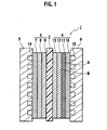
FIG. 1 is a cross-sectional view of a single cell constructing a solid polymer electrolyte fuel cell according to an embodiment of the present invention. -
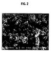
FIG. 2 is an enlarged cross-sectional picture obtained by observing a portion A of a firstmicroporous layer 11 shown inFIG. 1 by a field emission scanning electron microscope. -
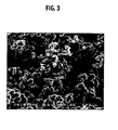
FIG. 3 is an enlarged cross-sectional picture obtained by observing a portion A of a secondmicroporous layer 2 shown inFIG. 1 by the field emission scanning electron microscope. -
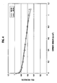
FIG. 4 is a view showing characteristics of cell voltages of Example 1. -
FIG. 5 is a view showing characteristics of cell voltages of Example 2. -
FIG. 6 is a view showing characteristics of cell voltages of Example 3. -
FIG. 7 is a view showing characteristics of cell voltages of Example 4. -
FIG. 8 is a view showing characteristics of cell voltages of Comparative example. - A description will be made below of a solid polymer electrolyte fuel cell and a cathode-side gas diffusion electrode according to an embodiment of the present invention with reference to the accompanying drawings.
-
FIG. 1 is a cross-sectional view of a single cell constructing the solid polymer electrolyte fuel cell according to the embodiment of the present invention. Asingle cell 1 is composed in such a manner that an anode-sidegas diffusion electrode 3 and a cathode-sidegas diffusion electrode 4 are arranged on both surfaces of asolid polymer membrane 2 and that an anode-side separator 5 and a cathode-side separator 6 are arranged on both surfaces of the joinedgas diffusion electrodes - The anode-side
gas diffusion electrode 3 is composed by sequentially stacking a fuel gasdiffusion layer substrate 7, amicroporous layer 8, and anelectrode catalyst layer 9, which are adjacent to the anode-side separator 5. Meanwhile, the cathode-sidegas diffusion electrode 4 is composed by sequentially stacking an oxidant gasdiffusion layer substrate 10, afirst microporous layer 11, asecond microporous layer 12, and anelectrode catalyst layer 13, which are adjacent to the cathode-side separator 6. - On the anode-
side separator 5 on a position side where the fuel gasdiffusion layer substrate 7 is disposed, a fuelgas flow passage 14 is formed, and through the fuelgas flow passage 14, fuel gas containing hydrogen is supplied to the anode. Moreover, on the cathode-side separator 6 on a position side where the oxidant gasdiffusion layer substrate 10 is disposed, an oxidant gas flow passage 15 is formed, and through the oxidant gas flow passage 15, oxidant gas containing oxygen is supplied to the cathode. - The
first microporous layer 11 andsecond microporous layer 12 of the cathode-sidegas diffusion electrode 4 are composed of microporous carbon layers having different water repellencies. An enlarged cross-sectional picture of a portion A in thefirst microporous layer 11 is shown inFIG. 2 , and an enlarged cross-sectional picture of a portion B in thesecond microporous layer 12 is shown inFIG. 3 . Note that the respective pictures shown inFIG 2 andFIG. 3 are obtained by observing the portion A in thefirst microporous layer 1 and the portion B in thesecond microporous layer 12 while enlarging the same portions A and B to magnification of 50000 by using a field emission scanning electron microscope ((UHR-FE-SEM) S5000, made by Hitachi, Ltd.) with an acceleration voltage of 2 kV. As shown in the pictures ofFIG. 2 andFIG. 3 , a mean diameter of pores present in thefirst microporous layer 11 is made smaller than a mean diameter of pores present in thesecond microporous layer 12, and water repellency of thesecond microporous layer 12 is made higher than that of thefirst microporous layer 11. Therefore, water generated in theelectrode catalyst layer 13 is pushed back without being allowed to pass through thesecond microporous layer 12 having the higher water repellency, and does not flow out from the cathode-side separator 6 side. As a result, theelectrode catalyst layer 13 and the solidpolymer electrolyte membrane 2 can be prevented from being dried. On the contrary, since water repellency of thefirst microporous layer 11 is made lower than that of thesecond microporous layer 12, the generated water is squeezed out to the oxidant gasdiffusion layer substrate 10 side and easily drained therefrom even in the case where the generated water enters the microporous layers. - It is preferable that the oxidant gas
diffusion layer substrate 10 of the cathode-sidegas diffusion electrode 4 be a porous substrate formed of cloth, carbon paper, nonwoven fabric, or the like, which is made of carbon fiber. - Moreover, it is preferable that the mean diameters of the pores present in the above-described
microporous layers porous substrate 10 made of the carbon fiber. The mean diameters of the pores of the microporous layers are differentiated, thus making it possible to easily drain the generated water from the microporous layers 11 and 12 to theporous substrate 10 no matter whether a treatment for the carbon fiber constructing the porous substrate may be a water-repellent treatment or a hydrophilic treatment, or no matter whether the carbon fiber may be hydrophilic or water-repellent. - Preferably, the mean diameters of the pores of the microporous layers 11 and 12 are set at 20 nm to 200 nm, more preferably, at 30 nm to 150 nm. Reasons for the above are as follows. When the mean diameters of the pores of the microporous layers 11 and 12 fall to less than 20 nm, drainability of the water generated in the electrode catalyst layer is entirely decreased, and a difference in drainability between the first microporous layer and the second microporous layer is reduced. On the contrary, when the mean diameters of the pores of the microporous layers 11 and 12 exceed 200 nm, the moisture retention of the electrode catalyst layer cannot be maintained. Hence, by defining the mean diameters of the pores of the microporous layers 11 and 12 within the above-described range, the excessive generated water which is generated in the
electrode catalyst layer 13 and enters the pores of the microporous layers 11 and 12 can be rapidly drained from theelectrode catalyst layer 13 owing to a capillary phenomenon, and the solidpolymer electrolyte membrane 2 can be prevented from being dried. - The above-described
microporous layers fist microporous layer 11 at 5 % by weight to 20 % by weight, and it is preferable to set the content of the water-repellent material in thesecond microporous layer 12 at 20 % by weight to 50 % by weight. As described above, the water repellencies of the microporous layers 11 and 12 are changed by changing the contents of the water-repellent resin by using the same type of carbon particles. Accordingly, either one of the carbon particles used as the microporous layers 11 and 12 does not become corroded, and durability of the microporous layers 11 and 12 is enhanced. - It is preferable to use a fluorine-based resin material as the water-repellent resin material, and in particular, it is preferable to use polytetrafluoroethylene or a copolymer of tetrafluoroethylene and hexafluoropropylene. By using the fluorine-based resin material, the durability of the microporous layers 11 and 12 is enhanced.
- Moreover, the above-described
microporous layers second microporous layer 12, a material containing hydrophobic carbon particles having a small specific surface area can also be used, and for thefirst microporous layer 11, a material containing hydrophilic carbon particles having a large specific surface area can also be used. As described above, thesecond microporous layer 12 is formed of the material containing the hydrophobic carbon particles, and a content of such a water-repellent resin composition in thesecond microporous layer 12 is reduced to the minimum, thus making it possible to reduce an influence given to the durability of the microporous layers 11 and 12, such as creep and mechanical deformation thereof. Moreover, thefirst microporous layer 11 is formed of the material containing the hydrophilic carbon materials, thus making it possible to retain the moisture on the surfaces of the hydrophilic carbon particles. Accordingly, even under an operating condition with low humidification and a low current density, humidities of the electrode catalyst layer and the solid polymer membrane can be maintained to be high, and the electrode catalyst layer and the solid polymer membrane can be prevented from being dried. Furthermore, with regard to the carbon particles forming the microporous layers, for example, it is preferable to set the specific surface area of the hydrophobic carbon particles at 200 m2/g or less, and it is preferable to set the specific surface area of the hydrophilic carbon particles at 200 m2/g or more. - The gas diffusion electrode is formed, in which the microporous layers which are the
first microporous layer 11 and thesecond microporous layer 12 are formed only on the cathode side as one surface of the solid polymer electrolyte membrane, thus making it possible to maintain the water repellencies and the moisture retentions in the microporous layers. Therefore, according to the solid polymer electrolyte fuel cell using the gas diffusion electrode with the above-described construction, even under an operating condition with wide humidity range and current density range, dry out of the solid polymer membrane and flooding can be prevented, and stable power generation performance can be obtained. - Next, a description will be made of more specific examples.
- Catalyst layers were formed on both surfaces of a polymer electrolyte membrane (Nafion 111 membrane, made by United States DuPont Corporation). As a catalyst which forms the catalyst layers, a Pt-carrying carbon catalyst (TEC 10E50E) with a carrying amount of 50% was used.
- A 5% Nafion solution (prepared by Aldrich Corporation), ultra pure water, IPA, and the Pt-carrying carbon catalyst were mixed together by every predetermined amount, were then agitated and mixed by using a rotary homogenizer, and catalyst ink was thus prepared. Note that the catalyst ink was prepared by the mixing while weighing ionomer and carbon so that weight ratios thereof could be 1.1: 1.0.
- Next, by using a screen printing method, the prepared catalyst ink was printed on one surface of each of two pieces of sheet-like PTFE so that the Pt-carrying amount could be 0.4 mg/cm2. Then, the catalyst ink thus printed was transferred to the polymer electrolyte membrane (Nafion 111 membrane) by a hot-pressing operation (150°C, 20 kgf/cm2, 5 minutes). Thus, a catalyst coated membrane (CCM) was fabricated.
- Carbon paper (TPG-H-090, made by Toray Industries, Inc.) was immersed into a PTFE-based fluid dispersion (Neoflon, prepared by Daikin Industries, Ltd.) diluted by pure water to have a predetermined concentration, followed by drying.
- First, the PTFE-based fluid dispersion (Neoflon, prepared by Daikin Industries, Ltd.) and carbon black particles (acetylene black: Denka Black AB-6 (specific surface area: 68 m2/g), made by Denki Kagaku Kogyo Kabushiki Kaisha) were dispersively mixed together in a wet process so that a ratio of the PTFE could be 20%. Thus, slurry was prepared. Next, the PTFE-based fluid dispersion (Neoflon, prepared by Daikin Industries, Ltd.) and carbon black particles (Vulcan XC-72R (specific surface area: 254 m2/g), made by Cabot Corporation) were dispersively mixed together in the wet process so that the ratio of the PTFE could be 20%. Thus, slurry was prepared.
- Thereafter, on filter paper of which surface is smooth, a solution of Denka Black OAB100 and 20% PTFE was applied, and then water was suction-extracted therefrom. Thereafter, on the filter paper, a solution of Vulcan XC-72R and 20% PTFE was applied, and water was suction-extracted therefrom one more time.
- Moreover, by the hot-pressing operation, the slurries were transferred onto the fabricated carbon paper already subjected to the water-repellent treatment, and were dried at room temperature, followed by a heat treatment at 340°C for 5 minutes. Thus, an MEA was fabricated.
- In Example 2, the fabrication method of the microporous layers was changed. Specifically, first, slurry was prepared, in which the PTFE-based fluid dispersion (prepared by Daikin Industries, Ltd.) and the carbon black particles (acetylene black:
Denka Black OAB 100, made by Denki Kagaku Kogyo Kabushiki Kaisha) were dispersively mixed together so that the ratio of the PTFE could be 20%. Next, slurry was prepared, in which the PTFE-based fluid dispersion (Daikin Industries, Ltd.) and carbon black particles (Ketjenblack EC (specific surface area: 800 m2/g): carbon black made by Ketjenblack International Corporation) were dispersively mixed together so that the ratio of the PTFE could be 20%. - Thereafter, on the filter paper of which surface is smooth, the solution of Denka Black OAB100 and 20% PTFE was applied, and then water was suction-extracted therefrom. Thereafter, on the filter paper, a solution of Ketjenblack EC and 20% PTFE was applied, and water was suction-extracted therefrom one more time.
- Moreover, by the hot-pressing operation, the slurries were transferred onto carbon paper already subjected to the water-repellent treatment, which was fabricated by using a similar method to that of Example 1, and were dried at the room temperature, followed by the heat treatment at 340°C for 15 minutes. Thus, an MEA was fabricated.
- In Example 3, the fabrication method of the microporous layers was changed. Specifically, first, slurry was prepared, in which the PTFE-based fluid dispersion (prepared by Daikin Industries, Ltd.) and the carbon black particles (Vulcan XC-72R, made by Cabot Corporation) were dispersively mixed together in the wet process so that the ratio of the PTFE could be 20%. Next, slurry was prepared, in which the PTFE-based fluid dispersion (prepared by Daikin Industries, Ltd.) and the carbon black particles (Vulcan XC-72R, made by Cabot Corporation) were dispersively mixed together in the wet process so that the ratio of the PTFE could be 40%.
- Thereafter, on the filter paper of which surface is smooth, a solution in which the ratio of the PTFE was 40% was applied, and then water was suction-extracted therefrom. Thereafter, on the filter paper, a solution in which the ratio of the PTFE was 20% was applied, and water was suction-extracted therefrom one more time. Subsequently, by the hot-pressing operation, the slurries were transferred onto the carbon paper already subjected to the water-repellent treatment, which was fabricated by using the similar method to that of Example 1, and were dried at the room temperature, followed by the heat treatment at 340°C for 15 minutes. Thus, an MEA was fabricated.
- In Example 4, the fabrication method of the microporous layers was changed. Specifically, first, slurry was prepared, in which the PTFE-based fluid dispersion (prepared by Daikin Industries, Ltd.) and the carbon black particles (Vulcan XC-72R, made by Cabot Corporation) were dispersively mixed together so that the ratio of the PTFE could be 20%. Next, slurry was prepared, in which the PTFE-based fluid dispersion (prepared by Daikin Industries, Ltd.) and the carbon black particles (Ketjenblack EC, made by Ketjenblack International Corporation) were dispersively mixed together in the wet process so that the ratio of the PTFE could be 20%.
- Thereafter, on the filter paper of which surface is smooth, the solution in which the ratio of the PTFE was 40% was applied, and then water was suction-extracted therefrom. Thereafter, on the filter paper, the solution in which the ratio of the PTFE was 20% was applied, and water was suction-extracted therefrom one more time. Subsequently, by the hot-pressing operation, the slurries were transferred onto the carbon paper already subjected to the water-repellent treatment, which was fabricated by using the similar method to that of Example 1, and were dried at the room temperature, followed by the heat treatment at 340°C for 15 minutes. Thus, an MEA was fabricated.
- Catalyst layers were individually formed on both surfaces of the polymer electrolyte membrane (Nafion 111 membrane, made by US DuPont Corporation). As a catalyst which forms the catalyst layers, the Pt-carrying carbon catalyst (TEC 10E50E) with a Pt-carrying amount of 50% was used.
- The 5% Nafion solution (prepared by Aldrich Corporation), the ultra pure water, the IPA, and the Pt-carrying carbon catalyst were mixed together by every predetermined amount, were then agitated and mixed by using the rotary homogenizer, and the catalyst ink was thus prepared. Note that the catalyst ink was prepared by the mixing while weighing the ionomer and the carbon so that weight ratios thereof could be 1.1: 1.0.
- Next, by using the screen printing method, the prepared catalyst ink was printed on both surfaces of the sheet-like PTFE so that the Pt-carrying amount could be 0.4 mg/cm2. Then, the catalyst ink thus printed was transferred to the polymer electrolyte membrane (Nafion 111 membrane) by the hot-pressing operation (150°C, 20 kgf/cm2, 5 minutes). Thus, a catalyst coated membrane (CCM) was fabricated.
- The carbon paper (TPG-H-090, made by Toray Industries, Inc.) was immersed into the PTFE-based fluid dispersion (Neoflon, prepared by Daikin Industries, Ltd.) diluted by the pure water to have the predetermined concentration, followed by drying.
- The carbon black particles (Vulcan XC-72R, made by Cabot Corporation) and the PTFE-based fluid dispersion (Neoflon, prepared by Daikin Industries, Ltd.) were dispersively mixed together in the wet process. Thus, slurry was prepared. The prepared slurry was applied to the filter paper of which surface is smooth, and then water was suction-extracted therefrom. Thereafter, by the hot-pressing operation, the slurry was transferred onto the carbon paper subjected to the water-repellent treatment. Subsequently, the slurry was dried at the room temperature, followed by the heat treatment at 340°C for 15 minutes. Thus, an MEA was fabricated.
- For the MEAs obtained from Examples 1 to 4 and Comparative example 1, which are described above, current-voltage (I-V) characteristics were measured. Note that the current-voltage (I-V) characteristics of the MEAs were measured by using the CCMs fabricated using the above-described production methods and a GDL and by assembling the MEAs to a cell voltage characteristics measuring jig under conditions where the anode and the cathode corresponded to the hydrogen and the air, respectively, a cell temperature was 70°C, a relative humidity of the anode was 100 RH%, and a relative humidity of the cathode was 40 RH% and 100 RH%. Measurement results of the current-voltage characteristics of the respective MEAs for Examples and Comparative example are shown in
FIG. 4 to FIG. 8 . - Moreover, resistance values of the cells, which were measured under conditions where the humidification was low (relative humidity of cathode: 40 RH%) and the current density was low (current density: 0.4 A/cm2), are shown in Table 1.
[Table 1] Resistance value of cell [mΩ·cm2] Example 1 131 Example 2 117 Example 3 121 Example 4 103 Comparative Example 110 - As a result of evaluating the characteristics of the respective cases, as shown in
FIG. 8 , it was proven that the cell voltage in the high current range was decreased under the condition where the humidification was high, and that the drainability and the gas diffusibility under the operation where the current density was high were decreased in the cathode. As opposed to this, in Example 1 to Example 4, which are shown inFIG. 4 to FIG. 7 , it was possible to restrict the decrease of the cell voltage in the high current range even under the condition where the humidification was high. As a result, it was proven that the drainability and the gas diffusibility under the operation where the current density was high were enhanced in the cathode, thus making it possible to prevent the flooding in the high current range even under the condition where the humidification was high. Moreover, it was proven that, by adopting the respective constructions from Example 1 to Example 4, the moisture retention was enhanced, thus making it possible to prevent the solid polymer membrane from being dried even in the case of performing the operation where the humidification was low. - It will be apparent for those skilled in the art that other various embodiments or various modifications may be contrived within the scope of claims, which is shown next.
- The gas diffusion electrode according to the present invention enhances the drainability of the generated water from the electrode catalyst layer to the gas diffusion layer, and the moisture retention and gas diffusibility of the electrode catalyst layer, and imparts the stable power generation characteristics to the fuel cell. Moreover, the solid polymer electrolyte fuel cell according to the present invention is good in terms of the drainability of the generated water and the moisture retention and gas diffusibility of the electrode catalyst layer even under the operating conditions where the humidification is low and high and the current density is low and high, and imparts thereto the stable power generation characteristics over the wide humidity range and current density range. Industrial applicabilities of both are high.
Claims (7)
- A gas diffusion electrode (4), comprising:an electrode catalyst layer (13);microporous layers (11, 12) arranged on the electrode catalyst layer (13), the microporous layers (11, 12) including at least two layers which are first and second microporous layers (11, 12) formed of materials having different water repellencies, wherein the second microporous layer (12) disposed on the electrode catalyst layer side is composed to have higher water repellency than the first microporous layer (11); andan oxidant gas diffusion substrate (10) disposed on the first microporous layer (11) and formed of carbon fiber;wherein a mean diameter of pores present in the microporous layers (11, 12) is 20 nm to 200 nm.
- A gas diffusion electrode (4) according to claim 1, wherein the mean diameter is smaller than a mean diameter of pores present in the oxidant gas diffusion substrate (10).
- A gas diffusion electrode (4) according to any one of claims 1 and 2, wherein the microporous layers (11, 12) are formed of a material containing carbon particles and water-repellent resin, a content of the water-repellent resin contained in the second microporous layer (12) is 20 % by weight to 50 % by weight, and a content of the water-repellent resin contained in the first microporous layer (11) is 5 % by weight to 20 % by weight.
- A gas diffusion electrode (4) according to any one of claims 1 and 2, wherein the microporous layers (11, 12) are formed of a material containing carbon particles and water-repellent resin, the second microporous layer (12) is formed of a material containing hydrophobic carbon particles, and the first microporous layer (11) is formed of a material containing hydrophilic carbon particles.
- A gas diffusion electrode (4) according to claim 4, wherein a specific surface area of the hydrophobic carbon particles is 200 m2/g or less, and a specific surface area of the hydrophilic carbon particles is 200 m2/g or more.
- A gas diffusion electrode (4) according to any one of claims 3 and 4, wherein the water-repellent resin is fluorine-based resin of polytetrafluoroethylene or a copolymer of tetrafluoroethylene and hexafluoropropylene.
- A solid polymer electrolyte fuel cell, comprising:a solid polymer electrolyte membrane;a gas diffusion electrode (4) according to any one of claims 1 to 6 disposed on the solid polymer electrolyte membrane; anda separator disposed on the gas diffusion electrode (4).
Applications Claiming Priority (2)
| Application Number | Priority Date | Filing Date | Title |
|---|---|---|---|
| JP2004182784A JP4691914B2 (en) | 2004-06-21 | 2004-06-21 | Gas diffusion electrode and solid polymer electrolyte fuel cell |
| PCT/JP2005/011339 WO2005124903A1 (en) | 2004-06-21 | 2005-06-21 | Gas diffusion electrode and solid-state high-molecular electrolyte type fuel cell |
Publications (3)
| Publication Number | Publication Date |
|---|---|
| EP1775788A1 EP1775788A1 (en) | 2007-04-18 |
| EP1775788A4 EP1775788A4 (en) | 2009-11-11 |
| EP1775788B1 true EP1775788B1 (en) | 2013-05-29 |
Family
ID=35510023
Family Applications (1)
| Application Number | Title | Priority Date | Filing Date |
|---|---|---|---|
| EP05753501.5A Expired - Fee Related EP1775788B1 (en) | 2004-06-21 | 2005-06-21 | Gas diffusion electrode and solid polymer electrolyte fuel cell |
Country Status (5)
| Country | Link |
|---|---|
| US (1) | US7749639B2 (en) |
| EP (1) | EP1775788B1 (en) |
| JP (1) | JP4691914B2 (en) |
| CA (2) | CA2571753C (en) |
| WO (1) | WO2005124903A1 (en) |
Families Citing this family (50)
| Publication number | Priority date | Publication date | Assignee | Title |
|---|---|---|---|---|
| US7722979B2 (en) * | 2005-10-14 | 2010-05-25 | Gm Global Technology Operations, Inc. | Fuel cells with hydrophobic diffusion medium |
| US20070154777A1 (en) * | 2006-01-05 | 2007-07-05 | Matsushita Electric Industrial Co., Ltd. The Penn State Research Foundation | Cathode electrodes for direct oxidation fuel cells and systems operating with concentrated liquid fuel at low oxidant stoichiometry |
| CN100472872C (en) * | 2006-02-01 | 2009-03-25 | 松下电器产业株式会社 | Direct oxidation fuel cell and method for operating direct oxidation fuel cell system |
| JP5165205B2 (en) * | 2006-03-14 | 2013-03-21 | 本田技研工業株式会社 | Membrane electrode structure for polymer electrolyte fuel cell |
| TWI318477B (en) | 2006-10-18 | 2009-12-11 | Ind Tech Res Inst | Fuel cell systems |
| US7704629B2 (en) * | 2007-01-22 | 2010-04-27 | Panasonic Corporation | Direct oxidation fuel cells with improved cathode gas diffusion media for low air stoichiometry operation |
| JP5207019B2 (en) * | 2007-02-05 | 2013-06-12 | ソニー株式会社 | Polymer electrolyte fuel cell and electronic device equipped with the same |
| US20080206615A1 (en) * | 2007-02-22 | 2008-08-28 | Paul Nicotera | Gas diffusion layer with controlled diffusivity over active area |
| US7785752B2 (en) * | 2007-03-07 | 2010-08-31 | Panasonic Corporation | Fuel cell electrode and method for producing the same |
| JP5151217B2 (en) | 2007-04-03 | 2013-02-27 | 株式会社日立製作所 | Fuel cell |
| JP5233183B2 (en) * | 2007-04-27 | 2013-07-10 | 株式会社エクォス・リサーチ | Fuel cell and fuel cell system. |
| US20080280164A1 (en) * | 2007-05-11 | 2008-11-13 | 3M Innovative Properties Company | Microporous carbon catalyst support material |
| JP5298469B2 (en) * | 2007-07-04 | 2013-09-25 | 日産自動車株式会社 | Gas diffusion electrode for fuel cell |
| JP5260009B2 (en) * | 2007-09-25 | 2013-08-14 | 株式会社Eneosセルテック | Membrane electrode assembly and fuel cell |
| KR101483125B1 (en) * | 2008-02-05 | 2015-01-15 | 삼성에스디아이 주식회사 | Membrane and electrode assembly for fuel cell, manufacturing method thereof, and fuel cell employing the same |
| JP5188872B2 (en) * | 2008-05-09 | 2013-04-24 | パナソニック株式会社 | Direct oxidation fuel cell |
| KR100984553B1 (en) * | 2008-07-30 | 2010-09-30 | 인하대학교 산학협력단 | Membrane electrode assembly for high concentration methanol fuel cells |
| JP5195286B2 (en) * | 2008-10-28 | 2013-05-08 | 旭硝子株式会社 | Manufacturing method of membrane electrode assembly for polymer electrolyte fuel cell |
| CN102257661B (en) * | 2009-09-10 | 2014-05-28 | 松下电器产业株式会社 | Gas diffusion layer and process for production thereof, and fuel cell |
| JP5238888B2 (en) * | 2009-10-16 | 2013-07-17 | パナソニック株式会社 | Membrane electrode assembly for fuel cell and fuel cell using the same |
| JP5441753B2 (en) * | 2010-02-19 | 2014-03-12 | Jx日鉱日石エネルギー株式会社 | Membrane electrode assembly and fuel cell |
| US8304145B2 (en) * | 2010-02-19 | 2012-11-06 | GM Global Technology Operations LLC | High tortuosity diffusion medium |
| WO2011109815A1 (en) * | 2010-03-05 | 2011-09-09 | A123 Systems, Inc. | Design and fabrication of electrodes with gradients |
| JP5924530B2 (en) * | 2011-06-17 | 2016-05-25 | 日産自動車株式会社 | Gas diffusion layer for fuel cells |
| JP5987440B2 (en) * | 2011-06-17 | 2016-09-07 | 日産自動車株式会社 | Fine porous layer sheet for fuel cell and method for producing the same |
| JP5630408B2 (en) * | 2011-09-13 | 2014-11-26 | トヨタ自動車株式会社 | Fuel cell |
| TWI568888B (en) * | 2011-09-15 | 2017-02-01 | 第諾拉工業公司 | Gas-diffusion electrode |
| JP5614462B2 (en) * | 2011-12-26 | 2014-10-29 | 東レ株式会社 | Gas diffusion electrode base material for fuel cell, membrane electrode assembly, and fuel cell |
| WO2013103338A1 (en) * | 2012-01-04 | 2013-07-11 | Utc Power Corporation | Reinforced microporous layer |
| KR20130114921A (en) * | 2012-04-10 | 2013-10-21 | 삼성에스디아이 주식회사 | Electrode for fuel cell, method of fabricating the same, and membrane-electrode assembly for fuel cell and fuel cell system including the same |
| JP5293859B1 (en) * | 2012-05-11 | 2013-09-18 | 大日本印刷株式会社 | Conductive porous layer for battery and method for producing the same |
| KR101881139B1 (en) * | 2012-06-29 | 2018-08-20 | 주식회사 제이앤티지 | Microporous layer used for fuel cell, gas diffusion layer comprising the same and fuel cell comprising the same |
| JP5862485B2 (en) | 2012-07-02 | 2016-02-16 | トヨタ自動車株式会社 | Method for forming gas diffusion layer for fuel cell |
| CN104541395A (en) * | 2012-07-19 | 2015-04-22 | 百拉得动力系统公司 | Microporous layer with hydrophilic additives |
| EP2911226B1 (en) * | 2012-10-19 | 2017-12-06 | Panasonic Intellectual Property Management Co., Ltd. | Fuel cell gas diffusion layer and method for manufacturing same |
| JP5614468B2 (en) * | 2013-03-08 | 2014-10-29 | 日産自動車株式会社 | Manufacturing method of gas diffusion electrode for fuel cell |
| JP6098430B2 (en) * | 2013-04-15 | 2017-03-22 | 旭硝子株式会社 | Polymer electrolyte fuel cell |
| CN103956505B (en) * | 2014-04-16 | 2016-04-13 | 武汉理工新能源有限公司 | A kind of fuel battery gas diffusion layer with water-retaining property and preparation method thereof and membrane electrode assembly and application |
| US20160049668A1 (en) * | 2014-08-15 | 2016-02-18 | GM Global Technology Operations LLC | Fuel cell with improved reactant distribution |
| CN105742666B (en) * | 2014-12-11 | 2018-05-18 | 中国科学院大连化学物理研究所 | A kind of fuel cell carbon nanotube gas diffusion layer and its preparation and application |
| CA2988934C (en) * | 2015-08-27 | 2023-11-21 | Toray Industries, Inc. | Gas diffusion electrode |
| CN108541350B (en) | 2015-12-24 | 2020-12-11 | 东丽株式会社 | Gas diffusion electrode and method for producing same |
| KR20180095845A (en) | 2015-12-24 | 2018-08-28 | 도레이 카부시키가이샤 | Gas diffusion electrode |
| WO2017110692A1 (en) | 2015-12-24 | 2017-06-29 | 東レ株式会社 | Gas diffusion electrode and fuel cell |
| US20190020040A1 (en) * | 2016-01-27 | 2019-01-17 | Toray Industries, Inc. | Gas diffusion electrode, microporous layer paint and production method thereof |
| CA3015334C (en) | 2016-03-29 | 2023-11-07 | Toray Industries, Inc. | Gas diffusion electrode base, laminate and fuel cell |
| GB201914335D0 (en) * | 2019-10-04 | 2019-11-20 | Johnson Matthey Fuel Cells Ltd | Membrane electrode assembly |
| KR20220096257A (en) * | 2020-12-30 | 2022-07-07 | 주식회사 제이앤티지 | Gas diffusion layer comprising a microporous layer having a through-path and/or a concentration gradient of a water-repellent resin in the thickness direction, and fuel cell comprising the same |
| WO2023157745A1 (en) * | 2022-02-18 | 2023-08-24 | 東レ株式会社 | Gas diffusion electrode for fuel cells |
| CN117039011A (en) * | 2023-07-28 | 2023-11-10 | 安徽瑞氢动力科技有限公司 | Composite microporous layer, preparation method thereof and proton exchange membrane fuel cell |
Family Cites Families (14)
| Publication number | Priority date | Publication date | Assignee | Title |
|---|---|---|---|---|
| JPH0665039B2 (en) * | 1986-07-03 | 1994-08-22 | 株式会社日立製作所 | Fuel cell using three-layer gas diffusion electrode |
| JPH0650039B2 (en) | 1988-10-28 | 1994-06-29 | 東京電力株式会社 | Form carrier for shield method |
| US5620807A (en) | 1995-08-31 | 1997-04-15 | The Dow Chemical Company | Flow field assembly for electrochemical fuel cells |
| JP3591123B2 (en) | 1996-03-08 | 2004-11-17 | トヨタ自動車株式会社 | Fuel cell and fuel cell electrode |
| JP3095746B1 (en) | 1999-09-21 | 2000-10-10 | メカテック有限会社 | Stacked battery manufacturing equipment |
| US6350539B1 (en) * | 1999-10-25 | 2002-02-26 | General Motors Corporation | Composite gas distribution structure for fuel cell |
| JP2001216973A (en) * | 2000-02-01 | 2001-08-10 | Toray Ind Inc | Electrode and its production as well as fuel cell using the same |
| JP3594533B2 (en) | 2000-05-30 | 2004-12-02 | 三洋電機株式会社 | Fuel cell |
| WO2002009221A1 (en) | 2000-07-25 | 2002-01-31 | Apollo Energy Systems, Incorporated | Additives to the gas supply of fuel cells with circulating electrolytes and means to regenerate used stacks |
| JP2003059498A (en) * | 2001-08-10 | 2003-02-28 | Equos Research Co Ltd | Fuel cell |
| JP5079195B2 (en) * | 2001-09-27 | 2012-11-21 | パナソニック株式会社 | Gas diffusion electrode for fuel cell and manufacturing method thereof |
| JP2003217599A (en) * | 2002-01-23 | 2003-07-31 | Matsushita Electric Ind Co Ltd | Solid polymer type fuel cell |
| TW558833B (en) * | 2002-09-09 | 2003-10-21 | Ind Tech Res Inst | Gas diffusion electrode and the method for making the same |
| JP6065039B2 (en) * | 2015-03-09 | 2017-01-25 | ダイキン工業株式会社 | Hot water supply control system |
-
2004
- 2004-06-21 JP JP2004182784A patent/JP4691914B2/en not_active Expired - Fee Related
-
2005
- 2005-06-21 US US11/571,010 patent/US7749639B2/en active Active
- 2005-06-21 CA CA2571753A patent/CA2571753C/en not_active Expired - Fee Related
- 2005-06-21 CA CA2767154A patent/CA2767154C/en not_active Expired - Fee Related
- 2005-06-21 WO PCT/JP2005/011339 patent/WO2005124903A1/en not_active Application Discontinuation
- 2005-06-21 EP EP05753501.5A patent/EP1775788B1/en not_active Expired - Fee Related
Also Published As
| Publication number | Publication date |
|---|---|
| JP4691914B2 (en) | 2011-06-01 |
| US20080299430A1 (en) | 2008-12-04 |
| CA2571753A1 (en) | 2005-12-29 |
| EP1775788A1 (en) | 2007-04-18 |
| EP1775788A4 (en) | 2009-11-11 |
| US7749639B2 (en) | 2010-07-06 |
| JP2006004879A (en) | 2006-01-05 |
| WO2005124903A1 (en) | 2005-12-29 |
| CA2767154C (en) | 2015-01-06 |
| CA2767154A1 (en) | 2005-12-29 |
| CA2571753C (en) | 2012-04-17 |
Similar Documents
| Publication | Publication Date | Title |
|---|---|---|
| EP1775788B1 (en) | Gas diffusion electrode and solid polymer electrolyte fuel cell | |
| JP4326179B2 (en) | Polymer electrolyte fuel cell | |
| KR100513183B1 (en) | Fuel cell | |
| US7803490B2 (en) | Direct methanol fuel cell | |
| US20070202388A1 (en) | Membrane Electrode Unit | |
| JP2006324104A (en) | Gas diffusion layer for fuel cell and fuel cell using this | |
| JP5034172B2 (en) | Gas diffusion layer for fuel cell and fuel cell using the same | |
| US11811070B2 (en) | Fuel cell membrane electrode assembly and polymer electrolyte fuel cell | |
| JP5105888B2 (en) | Gas diffusion electrode, fuel cell, and method of manufacturing gas diffusion electrode | |
| JP5151217B2 (en) | Fuel cell | |
| JP2005228755A (en) | Polymer electrolyte fuel cell | |
| JP2003178780A (en) | Polymer electrolyte type fuel cell system and operating method of polymer electrolyte type fuel cell | |
| JP2001307749A (en) | Solid polymer fuel battery and stack of the same | |
| JP2005174835A (en) | Electrode | |
| JP2006085984A (en) | Mea for fuel cell and fuel cell using this | |
| JP4686992B2 (en) | Solid polymer fuel cell and power generation method thereof | |
| JP2006049115A (en) | Fuel cell | |
| JP2009043688A (en) | Fuel cell | |
| JP2008071633A (en) | Solid polymer electrolyte fuel cell | |
| US10707510B2 (en) | Membrane electrode assembly | |
| JP2002289201A (en) | Fuel cell | |
| JP2002289200A (en) | Fuel battery | |
| JP2006019128A (en) | Gas diffusion layer and fuel cell using this | |
| US20230112131A1 (en) | Reversible shunts for overcharge protection in polymer electrolyte membrane fuel cells | |
| JP2006120507A (en) | Solid polymer fuel cell |
Legal Events
| Date | Code | Title | Description |
|---|---|---|---|
| PUAI | Public reference made under article 153(3) epc to a published international application that has entered the european phase |
Free format text: ORIGINAL CODE: 0009012 |
|
| 17P | Request for examination filed |
Effective date: 20061222 |
|
| AK | Designated contracting states |
Kind code of ref document: A1 Designated state(s): DE FR GB |
|
| DAX | Request for extension of the european patent (deleted) | ||
| RBV | Designated contracting states (corrected) |
Designated state(s): DE FR GB |
|
| A4 | Supplementary search report drawn up and despatched |
Effective date: 20091012 |
|
| 17Q | First examination report despatched |
Effective date: 20110907 |
|
| GRAP | Despatch of communication of intention to grant a patent |
Free format text: ORIGINAL CODE: EPIDOSNIGR1 |
|
| RIN1 | Information on inventor provided before grant (corrected) |
Inventor name: YAMAMOTO, MASAHIRO C/O NISSAN MOTOR CO., LTD. Inventor name: WAKI, NORIHISA C/O NISSAN MOTOR CO., LTD. Inventor name: ICHIKAWA, SATORU C/O NISSAN MOTOR CO., LTD. |
|
| GRAS | Grant fee paid |
Free format text: ORIGINAL CODE: EPIDOSNIGR3 |
|
| GRAA | (expected) grant |
Free format text: ORIGINAL CODE: 0009210 |
|
| AK | Designated contracting states |
Kind code of ref document: B1 Designated state(s): DE FR GB |
|
| REG | Reference to a national code |
Ref country code: GB Ref legal event code: FG4D |
|
| REG | Reference to a national code |
Ref country code: DE Ref legal event code: R096 Ref document number: 602005039805 Country of ref document: DE Effective date: 20130725 |
|
| PLBE | No opposition filed within time limit |
Free format text: ORIGINAL CODE: 0009261 |
|
| STAA | Information on the status of an ep patent application or granted ep patent |
Free format text: STATUS: NO OPPOSITION FILED WITHIN TIME LIMIT |
|
| 26N | No opposition filed |
Effective date: 20140303 |
|
| REG | Reference to a national code |
Ref country code: DE Ref legal event code: R097 Ref document number: 602005039805 Country of ref document: DE Effective date: 20140303 |
|
| REG | Reference to a national code |
Ref country code: FR Ref legal event code: PLFP Year of fee payment: 12 |
|
| REG | Reference to a national code |
Ref country code: FR Ref legal event code: PLFP Year of fee payment: 13 |
|
| REG | Reference to a national code |
Ref country code: FR Ref legal event code: PLFP Year of fee payment: 14 |
|
| PGFP | Annual fee paid to national office [announced via postgrant information from national office to epo] |
Ref country code: DE Payment date: 20180605 Year of fee payment: 14 |
|
| PGFP | Annual fee paid to national office [announced via postgrant information from national office to epo] |
Ref country code: FR Payment date: 20180511 Year of fee payment: 14 |
|
| PGFP | Annual fee paid to national office [announced via postgrant information from national office to epo] |
Ref country code: GB Payment date: 20180403 Year of fee payment: 14 |
|
| REG | Reference to a national code |
Ref country code: DE Ref legal event code: R119 Ref document number: 602005039805 Country of ref document: DE |
|
| GBPC | Gb: european patent ceased through non-payment of renewal fee |
Effective date: 20190621 |
|
| PG25 | Lapsed in a contracting state [announced via postgrant information from national office to epo] |
Ref country code: DE Free format text: LAPSE BECAUSE OF NON-PAYMENT OF DUE FEES Effective date: 20200101 Ref country code: GB Free format text: LAPSE BECAUSE OF NON-PAYMENT OF DUE FEES Effective date: 20190621 |
|
| PG25 | Lapsed in a contracting state [announced via postgrant information from national office to epo] |
Ref country code: FR Free format text: LAPSE BECAUSE OF NON-PAYMENT OF DUE FEES Effective date: 20190630 |