EP1096102A1 - Leitergelenk - Google Patents
Leitergelenk Download PDFInfo
- Publication number
- EP1096102A1 EP1096102A1 EP00121424A EP00121424A EP1096102A1 EP 1096102 A1 EP1096102 A1 EP 1096102A1 EP 00121424 A EP00121424 A EP 00121424A EP 00121424 A EP00121424 A EP 00121424A EP 1096102 A1 EP1096102 A1 EP 1096102A1
- Authority
- EP
- European Patent Office
- Prior art keywords
- ladder
- shaft
- joint according
- release lever
- recesses
- Prior art date
- Legal status (The legal status is an assumption and is not a legal conclusion. Google has not performed a legal analysis and makes no representation as to the accuracy of the status listed.)
- Granted
Links
- 230000006835 compression Effects 0.000 claims abstract description 6
- 238000007906 compression Methods 0.000 claims abstract description 6
- 239000004020 conductor Substances 0.000 claims description 28
- 210000002414 leg Anatomy 0.000 description 11
- 239000000463 material Substances 0.000 description 9
- 239000011324 bead Substances 0.000 description 6
- 210000001331 nose Anatomy 0.000 description 5
- 238000004519 manufacturing process Methods 0.000 description 3
- 238000003892 spreading Methods 0.000 description 2
- 230000004888 barrier function Effects 0.000 description 1
- 230000005540 biological transmission Effects 0.000 description 1
- 210000000887 face Anatomy 0.000 description 1
- 210000003746 feather Anatomy 0.000 description 1
- 238000003825 pressing Methods 0.000 description 1
- 238000003860 storage Methods 0.000 description 1
- 210000000689 upper leg Anatomy 0.000 description 1
Images



Classifications
-
- E—FIXED CONSTRUCTIONS
- E06—DOORS, WINDOWS, SHUTTERS, OR ROLLER BLINDS IN GENERAL; LADDERS
- E06C—LADDERS
- E06C1/00—Ladders in general
- E06C1/02—Ladders in general with rigid longitudinal member or members
- E06C1/32—Ladders with a strut which is formed as a ladder and can be secured in line with the ladder
Definitions
- the invention relates to a conductor joint, which two around a joint axis Rotatably connected shafts, the shafts made of two U-profiles are formed, which with the end faces of the free ends the thighs meet.
- Conductor joints of this type are known from the prior art. These well-known Conductor joints are made with rivet or screw connections with a Ladder beam connected. To do this, the shafts of the conductor joint in the ladder bars are inserted so that shafts and ladder bars are in one Overlap area. Then in recesses of the ladder stile and in recesses in the shafts of the conductor joint, the fastening elements used.
- the invention is therefore based on the object of proposing a ladder joint, which has stems that are permanently fixed in a simple manner and can be connected wobble-free with a ladder bar.
- At least one Leg with at least one recess open to its end face is provided, which is intended for receiving fasteners.
- the Ladder bars are drilled at the appropriate points so that fasteners, e.g. Spreading elements in holes in the ladder stiles and in the cutouts at the ends of the U-profiles can be used.
- the fasteners push the two U-profiles apart, so that the webs connecting the two legs of the U-profiles against the Inner rail surface can be pressed.
- the shafts are therefore large on the inside of the ladder stiles. This leads to a special one stable and wobble-free connection between ladder stiles and ladder joint, since the connection on the narrow side of the spars for force transmission represents the advantageous position.
- the cutouts in the one another abutting legs are arranged in pairs opposite each other.
- the cutouts advantageously have a semicircular surface.
- the shafts at the free ends of the cross section of the ladder rung have adapted recesses that have a Have opening width which is at least the width of the cross section of a Ladder rung corresponds and that the length of the shafts of the ladder joint is dimensioned such that the recesses enclose the ladder rungs and the stems come to rest on the ladder rungs.
- the one in the stile inserted shaft can be supported on the first ladder rung, and the shaft is therefore free to move in the longitudinal direction limited. This increases the stability of the connection between the ladder joint and the ladder rung.
- edges of the recesses are advantageously bent inwards.
- the Shafts of the ladder joint are so far into the ladder stile during assembly pushed in until the bent edges rest on the rung. This creates between the outside of the cranked surface and the Ladder bar a crack. In this gap is then - preferably from Corners of the ladder rung - material of the ladder rung pressed in.
- the ladder rung will also be on the inside of the cranked surface widened so that the edges of the recess are firmly between two material beads the ladder rung.
- the ladder rung is also in the areas adjacent to the outer surface of the ladder stile.
- the conductor joint has a first Shafts a locking disc concentric to the joint axis, which in Distributed area of their circumference according to the positions of the joint Has grooves.
- the second shaft of the conductor joint then has two of them spaced shells, between which the locking disc engages.
- the barrier layer is a guided on the second shaft Locking piece can be inserted.
- the locking piece is then on by means of a the second shaft rotatably mounted release lever from the respective grooves the locking disc can be lifted out.
- the ladder joint can be set at different angles as required be determined.
- the locking piece can then have a compression spring, the compression spring holding the locking piece in its locked position, while the lock washer in the same direction, one next to the grooves Has nose that forms a stop surface for the locking piece.
- These lugs are formed by the side surfaces of the grooves are higher on the same side than the opposite side surfaces of the grooves. The locking piece strikes when the conductor joint is turned with its lateral surface against these noses and then clicks into place the spring pressure directly into the groove of the locking disc. Thereby is prevented that the Latch of the locking piece slips out of the groove in the locking disk.
- the release lever two lying on its pivot axis in Cross-section essentially rectangular pin for the storage of the release lever have on the second shaft.
- the second shaft in the Shells each have a recess that has a cross section that is approximately each corresponds to two opposite sectors of a circle. So they can Pins - and thus the release lever - are stored in these recesses, while the release lever between two through the edges of these recesses fixed positions is pivotable.
- the release lever is advantageously connected to an actuating lever.
- To the actuating lever can bend into the release lever have, the bend has an approach that one Key bit is similar.
- the release lever then has a cross-sectional shape recess corresponding to the approach, so that the recess has a Offers point of attack for the operating lever.
- Such an operating lever can according to the invention via a parallel to the top rung of the ladder segment connectable with an actuating lever of a further conductor joint of a conductor his. Then can on the actuating or on the release lever Be attached end of a spring, the other end then according to the invention either directly on the second shaft or on a tab for the guide of the locking piece is attached.
- the Operating lever are held in a rest position, in which advantageous the lever of the operating lever against the parallel rung is held down.
- the spring can be inside of the second shaft. As a result, the spring is against accidental and unintentional loosening protected.
- a stop for the actuating lever is advantageous on the second shaft intended.
- This stop is advantageously formed by a rivet, which connects the two U-profiles of the second shaft.
- the fastening elements can be material bulges a spar wall of a ladder spar or around Act screws or rivets.
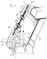
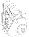
- a conductor joint according to the invention has two shafts 2, 3, which are rotatably connected.
- the shafts 2, 3 are made of each two U-profiles 21, 31 formed, which with the free ends of the Legs 22, 32 lie against each other.
- the two U-profiles 21 of the first Shafts 2 have a locking disk concentric with the hinge axis 25, which has grooves 26 in the area of its circumference.
- the grooves 26 are provided in accordance with the angular positions in the locking disk 25, in which the conductor joint should be adjustable.
- the second shaft 3 overlaps the first with two spaced apart shells 311 Shaft 2, so that the locking disk 25 in the joint-forked end of the second shaft 3 protrudes.
- a longitudinally displaceable, spring-loaded locking piece 35 On the second shaft 3 is a longitudinally displaceable, spring-loaded locking piece 35 provided, which can be inserted into the grooves 26 of the locking disk 25 is.
- the locking piece 35 is in a tab 361 of the second Shaft 3 guided, and a compression spring 37 (not shown in FIGS. 1 and 2) presses the locking piece into the grooves 26 of the locking disk 25.
- the locking disk 25 has in addition to the grooves 26 lugs which have a stop surface for form the bolt 36 of the locking piece 37. This will make these noses formed that the walls of the grooves are higher on the same side than the walls on the opposite side of the grooves. These noses 27 cause a simplified engagement of the latch 36 in the grooves 26.
- Der Bolt 36 can by means of a release lever 38, which is on the second shaft 3 is stored, can be lifted out of the grooves 26 to the conductor joint 1 can be unlocked and brought into another angular position.
- the release lever 38 has two cross-sections lying on its pivot axis essentially rectangular pins 381. These pins 381 serve the mounting of the release lever 38 on the second shaft 3 the shells 311 of the second shaft 3 recesses 312 are provided, which have a cross-section that is essentially two opposite Sectors of a circle. The pins 381 and therefore also the release lever 38 are in these recesses 312 between two the edges of the sectors pivotal positions.
- the release lever 38 has a recess 39.
- an actuating lever 6 can be used in a rotationally fixed manner.
- the operating lever 6 an angled portion 61, which has a beard-like Approach 62 is provided.
- the rectangular cross section of this bend 61 with the approach 62 corresponds to the rectangular cross section of a recess 39 in the release lever 38.
- the actuating lever 6 is in the recess 39 of the release lever 38 is used, there is a rotationally fixed connection between release lever 38 and actuation lever 6.
- the release lever 38 presses against the locking piece 35, lifts it out of the groove 26, and the conductor joint 1 can be twisted become.
- a spring 64 is used (neglected in FIGS. 1 and 2).
- This Spring 64 holds the release lever 38 and in particular the actuating lever 6 in a starting position. In this starting position is the one not shown Bracket of the operating lever 6 on the top rung.
- a stop 7 for the actuating lever on the second shaft 3 6 is formed by a rivet, which also connects the two U-profiles 31 of the second shaft.
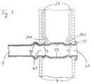
- the shafts 2, 3 have the cross section of the rung at the free ends 5 adapted recesses 24, 34. These recesses 24, 34 have an opening width which is essentially the width of the cross section the ladder rung 5 corresponds.
- the length of the Shafts 2, 3 of the conductor joint 1 are dimensioned such that the recesses 24, 34 include the ladder rung 5 without a spool and the shafts 2, 3 on the Ladder rungs, which are inserted in receptacles 41 of the ladder stiles, for Plant come.
- the recesses have a rectangular shape and are designed in such a way that they touch the rung 5 as far as possible.
- the U-profiles 21, 31 of the shafts 2, 3 have in the end faces of the free Ends of the legs 22, 32 cutouts 23 open towards the end face, 33 on. These recesses 23, 33 lie against each other Legs 22, 32 each in pairs opposite and have a semicircular Area.
- the ladder stiles 4 are then provided with holes, so that at the inserted into the stiles 4 shafts 2, 3 the holes of the Ladder bars and the cutouts are on top of each other. This can then a spreading element is inserted into the bores and the recesses 23, 33 become. This expansion element presses the two U-profiles of the shafts 2, 3 apart, so that the webs connecting the legs together U-profiles are pressed against the ladder bars 4.
Landscapes
- Ladders (AREA)
Abstract
Description
- Fig. 1
- eine Ansicht eines erfindungsgemäßen Leitergelenkes, verbunden mit Leiterholmen,
- Fig. 2
- das erfindungsgemäße Leitergelenk gemäß Fig. 1 in vergrößerter Darstellung,
- Fig. 3
- das erfindungsgemäße Leitergelenk gemäß Fig. 1, jedoch ohne Leiterholme und -sprossen,
- Fig. 3a
- ein Detail des erfindungsgemäßen Leitergelenkes gemäß Fig. 3,
- Fig. 4
- einen Schnitt durch das erfindungsgemäße Leitergelenk gemäß der Linie IV - IV in Fig. 1,
- Fig. 5
- einen Schnitt durch das erfindungsgemäße Leitergelenk gemäß der Linie V-V in Fig. 1,
- Fig. 6
- ein Detail des Leitergelenkes gemäß Fig. 5 und
- Fig. 7
- einen Schnitt durch die Verbindung zwischen Schaft, Leiterholm und oberster Leitersprosse.
- 1
- Leitergelenk
- 2
- erster Schaft
- 21
- U-Profil
- 22
- Schenkel des U-Profils
- 23
- Aussparungen in den Enden der Schenkel
- 24
- Ausnehmung
- 241
- abgekröpfter Rand
- 25
- Sperrscheibe
- 26
- Nuten
- 27
- Nase
- 3
- zweiter Schaft
- 31
- U-Profil
- 311
- Schalen
- 312
- Ausnehmungen für die Zapfen
- 32
- Schenkel des U-Profils
- 33
- Aussparungen in den Enden der Schenkel
- 331
- Niet
- 34
- Ausnehmung
- 341
- abgekröpfter Rand
- 35
- Sperrstück
- 361
- Lasche
- 37
- Druckfeder
- 38
- Lösehebel
- 381
- Zapfen
- 39
- Ausnehmung im Lösehebel
- 4
- Leiterholme
- 41
- Aufnahme
- 5
- Leitersprosse
- 51
- Materialwulst außerhalb des Leiterholmes
- 52
- Materialwulst innerhalb des Schaftes
- 53
- Materialwulst zwischen Leiterholm und Schaft
- 6
- Betätigungshebel
- 61
- Abwinkelung
- 62
- Ansatz
- 64
- Feder
- 7
- Anschlag
Claims (19)
- Leitergelenk, welches zwei um eine Gelenkachse drehbar miteinander verbundene Schäfte (2, 3) aufweist, wobei die Schäfte (2, 3) aus zwei U-Profilen (21, 31) gebildet sind, welche mit den Stirnflächen der freien Enden der Schenkel (22, 32) aneinander stoßen,
dadurch gekennzeichnet, dass
zumindest ein Schenkel (22, 32) mit zumindest einer zu seiner Stirnseite hin offenen Aussparung (23, 33) versehen ist, welche zur Aufnahme von Befestigungselementen bestimmt ist. - Leitergelenk nach Anspruch 1, dadurch gekennzeichnet, dass die Aussparungen (23, 33) in den aneinander stoßenden Schenkeln (22, 32) jeweils paarig gegenüberliegend angeordnet sind.
- Leitergelenk nach einem der Ansprüche 1 oder 2, dadurch gekennzeichnet, dass die Aussparungen (23, 33) eine halbkreisförmige Fläche haben.
- Leitergelenk für den Einsatz in Leiterholmen mit Leitersprossen (5) nach einem der Ansprüche 1 bis 3, dadurch gekennzeichnet, dass die Schäfte (2, 3) in die Leiterholme (4) einschiebbar sind, dass die Schäfte (2, 3) an den freien Enden dem Querschnitt der Leitersprosse (5) angepasste Ausnehmungen (24, 34) aufweisen, die eine Öffnungsweite haben, welche zumindest der Breite des Querschnittes einer Leitersprosse (5) entspricht und dass die Länge der Schäfte (2, 3) des Leitergelenkes (1) derart bemessen ist, dass die Ausnehmungen (24, 34) die Leitersprossen (5) umfassen und die Schäfte (2, 3) auf den Leitersprossen (5) zur Anlage kommen.
- Leitergelenk nach Anspruch 4, dadurch gekennzeichnet, dass die Ränder (241, 341) der Ausnehmungen (24, 34) zumindest teilweise nach innen abgekröpft sind.
- Leitergelenk nach Anspruch 5, dadurch gekennzeichnet, dass die Ausnehmungen (24, 34) rechteckig sind.
- Leitergelenk nach Anspruch 5 oder 6, dadurch gekennzeichnet, dass die Ränder der Ausnehmungen (24, 34) die Leitersprosse spielfrei umfassen.
- Leitergelenk nach einem der Ansprüche 1 bis 7, dadurch gekennzeichnet, dass ein erster Schaft (2) eine zur Gelenkachse konzentrische Sperrscheibe (25) aufweist, die im Bereich ihres Umfanges entsprechend den Stellungen des Leitergelenkes (1) verteilte Nuten (26) hat, dass der zweite Schaft (3) zwei beabstandete Schalen (311) hat, zwischen welche die Sperrscheibe (25) greift, dass in die Nuten (26) der Sperrscheibe ein an dem zweiten Schaft (3) längsverschieblich geführtes Sperrstück (35) einschiebbar ist, dass das Sperrstück (35) mittels eines an dem zweiten Schaft (3) drehbar gelagerten Lösehebels (38) aus den jeweiligen Nuten (26) aushebbar ist.
- Leitergelenk nach Anspruch 8, dadurch gekennzeichnet, dass das Sperrstück (35) eine Druckfeder aufweist, die das Sperrstück (35) in seiner eingerasteten Stellung hält und dass die Seitenflächen (27) der Nuten (26) jeweils auf der gleichen Seite höher sind als die gegenüberliegenden Seitenflächen der Nuten (26), so dass an den Nuten eine Anschlagfläche für das Sperrstück (35) ausgebildet ist.
- Leitergelenk nach einem der Ansprüche 8 oder 9, dadurch gekennzeichnet, dass der Lösehebel (38) mit einem Betätigungshebei (6) verbunden ist.
- Leitergelenk nach Anspruch 10, dadurch gekennzeichnet, dass der Betätigungshebei (6) eine in den Lösehebel (38) eingreifende erste Abwinkelung (61) aufweist, dass diese Abwinkelung (61) einen Ansatz (62) hat, welcher einem Schlüsselbart ähnlich ist und dass der Lösehebel (38) eine der Querschnittsform des Ansatzes (62) entsprechende Ausnehmung (39) hat, so dass die Ausnehmung (39) einen Angriffspunkt für den Betätigungshebel (6) bietet.
- Leitergelenk nach Anspruch 10 oder 11, dadurch gekennzeichnet, dass der Betätigungshebel (6) mit einem Betätigungshebel eines weiteren Leitergelenkes einer Leiter verbindbar ist.
- Leitergelenk nach einem der Ansprüche 8 bis 12, dadurch gekennzeichnet, dass der Lösehebel (38) zwei auf seiner Schwenkachse liegende und im Querschnitt im Wesentlichen rechteckige Zapfen (381) aufweist, dass der dem Lösehebel zugeordnete zweite Schaft (3) jeweils eine Ausnehmung (312) mit einem Querschnitt hat, der in etwa je zwei gegenüberliegenden und ineinander übergreifenden Sektoren eines Kreises entspricht und dass die Zapfen (381) in diesen Ausnehmungen (312) gelagert sind, so dass der Lösehebel (38) zwischen zwei festgelegten Positionen schwenkbar ist.
- Leitergelenk nach einem der Ansprüche 11 bis 13, dadurch gekennzeichnet, dass an dem Betätigungs- oder dem Lösehebel ein Ende einer Feder angebracht ist, deren anderes Ende entweder unmittelbar an dem Schaft (3) oder an einer Lasche (361) für die Führung des Sperrstückes (35) befestigt ist.
- Leitergelenk nach Anspruch 14, dadurch gekennzeichnet, dass die Feder (64) den Bügel des Betätigungshebels (6) gegen die Leitersprosse gedrückt hält.
- Leitergelenk nach Anspruch 14 oder 15, dadurch gekennzeichnet, dass die Feder (64) innerhalb des zweiten Schaftes (3) angeordnet ist.
- Leitergelenk nach einem der Ansprüche 11 bis 16, dadurch gekennzeichnet, dass an dem zweiten Schaft (3) ein Anschlag (7) für den Betätigungshebel (6) angebracht ist, welcher die beiden U-Profile (31) des Schaftes miteinander verbindet.
- Leitergelenk nach einem der Ansprüche 1 bis 17, dadurch gekennzeichnet, dass die Befestigungselemente Materialauswölbungen einer Holmwandung eines Leiterholmes sind.
- Leitergelenk nach einem der Ansprüche 1 bis 17, dadurch gekennzeichnet, dass die Befestigungselemente Nieten oder Schrauben sind.
Applications Claiming Priority (2)
| Application Number | Priority Date | Filing Date | Title |
|---|---|---|---|
| DE29919002U | 1999-10-29 | ||
| DE29919002U DE29919002U1 (de) | 1999-10-29 | 1999-10-29 | Leitergelenk |
Publications (2)
| Publication Number | Publication Date |
|---|---|
| EP1096102A1 true EP1096102A1 (de) | 2001-05-02 |
| EP1096102B1 EP1096102B1 (de) | 2006-03-01 |
Family
ID=8080897
Family Applications (1)
| Application Number | Title | Priority Date | Filing Date |
|---|---|---|---|
| EP00121424A Expired - Lifetime EP1096102B1 (de) | 1999-10-29 | 2000-09-29 | Anordnung aufweisend ein Leitergelenk für den Einsatz in Leiterholmen und Befestigungselemente |
Country Status (4)
| Country | Link |
|---|---|
| EP (1) | EP1096102B1 (de) |
| AT (1) | ATE318984T1 (de) |
| DE (2) | DE29919002U1 (de) |
| ES (1) | ES2258434T3 (de) |
Cited By (1)
| Publication number | Priority date | Publication date | Assignee | Title |
|---|---|---|---|---|
| CN109154172A (zh) * | 2016-06-14 | 2019-01-04 | 伟英企业有限公司 | 梯子、梯子铰链和相关方法 |
Citations (4)
| Publication number | Priority date | Publication date | Assignee | Title |
|---|---|---|---|---|
| DE3737295A1 (de) * | 1987-11-04 | 1989-05-18 | Krause Werk Gmbh & Co Kg | Gelenk fuer leitern |
| DE4344921A1 (de) * | 1993-12-30 | 1995-07-06 | Rauschenberger Metallwaren Gmb | Verfahren und Vorrichtung zum Verbinden von wenigstens zwei Bauteilen |
| DE19517227A1 (de) * | 1995-05-11 | 1996-11-14 | Brennenstuhl Kg Hugo | Leiter |
| DE19539157A1 (de) * | 1995-10-20 | 1997-04-24 | Hymer Leichtmetallbau | Verbindung eines Leiterprofils mit einem eingesteckten Innenteil |
Family Cites Families (3)
| Publication number | Priority date | Publication date | Assignee | Title |
|---|---|---|---|---|
| DE3211164C2 (de) | 1982-03-26 | 1985-06-20 | Günther 6320 Alsfeld Krause | Zusammenklappbare Mehrzweckleiter |
| DE3937535C1 (en) | 1989-11-10 | 1991-03-07 | Rauschenberger Metallwaren Gmbh, 7144 Asperg, De | Joint for folding ladder - has swivel legs with ratchet disc and stop to control pivoting |
| DE29600583U1 (de) | 1996-01-15 | 1996-03-07 | Dofair Company Ltd., Keelung | Gelenkverbindung für eine Klappleiter |
-
1999
- 1999-10-29 DE DE29919002U patent/DE29919002U1/de not_active Expired - Lifetime
-
2000
- 2000-09-29 ES ES00121424T patent/ES2258434T3/es not_active Expired - Lifetime
- 2000-09-29 DE DE50012283T patent/DE50012283D1/de active Active
- 2000-09-29 EP EP00121424A patent/EP1096102B1/de not_active Expired - Lifetime
- 2000-09-29 AT AT00121424T patent/ATE318984T1/de not_active IP Right Cessation
Patent Citations (4)
| Publication number | Priority date | Publication date | Assignee | Title |
|---|---|---|---|---|
| DE3737295A1 (de) * | 1987-11-04 | 1989-05-18 | Krause Werk Gmbh & Co Kg | Gelenk fuer leitern |
| DE4344921A1 (de) * | 1993-12-30 | 1995-07-06 | Rauschenberger Metallwaren Gmb | Verfahren und Vorrichtung zum Verbinden von wenigstens zwei Bauteilen |
| DE19517227A1 (de) * | 1995-05-11 | 1996-11-14 | Brennenstuhl Kg Hugo | Leiter |
| DE19539157A1 (de) * | 1995-10-20 | 1997-04-24 | Hymer Leichtmetallbau | Verbindung eines Leiterprofils mit einem eingesteckten Innenteil |
Cited By (4)
| Publication number | Priority date | Publication date | Assignee | Title |
|---|---|---|---|---|
| CN109154172A (zh) * | 2016-06-14 | 2019-01-04 | 伟英企业有限公司 | 梯子、梯子铰链和相关方法 |
| US10801261B2 (en) | 2016-06-14 | 2020-10-13 | Wing Enterprises, Incorporated | Ladders, ladder hinges and related methods |
| CN109154172B (zh) * | 2016-06-14 | 2021-03-09 | 伟英企业有限公司 | 梯子、梯子铰链和相关方法 |
| US11988043B2 (en) | 2016-06-14 | 2024-05-21 | Little Giant Ladder Systems, Llc | Ladders, ladder hinges and related methods |
Also Published As
| Publication number | Publication date |
|---|---|
| EP1096102B1 (de) | 2006-03-01 |
| DE29919002U1 (de) | 2000-02-03 |
| ATE318984T1 (de) | 2006-03-15 |
| DE50012283D1 (de) | 2006-04-27 |
| ES2258434T3 (es) | 2006-09-01 |
Similar Documents
| Publication | Publication Date | Title |
|---|---|---|
| EP0425786B1 (de) | Leiter | |
| WO2001073302A2 (de) | Rohrelement | |
| DE10033309A1 (de) | Kraftfahrzeugtürverschluss | |
| EP1096102B1 (de) | Anordnung aufweisend ein Leitergelenk für den Einsatz in Leiterholmen und Befestigungselemente | |
| DE10355495A1 (de) | Zerlegbares Gerüst | |
| EP1096101B1 (de) | Leitergelenk | |
| DE10015095C2 (de) | Verriegelungsvorrichtung für einen Türflügel | |
| EP1580370B1 (de) | Beschlaganordnung | |
| EP2085543B1 (de) | Schloss | |
| WO2008068304A2 (de) | Treibstangengetriebe | |
| DE2330897B2 (de) | Anordnung zur Befestigung von Beschlagteilen an dem Blendrahmen oder Flügelrahmen von Fenstern, Türen oder dergleichen | |
| CH620734A5 (en) | Automatic roller-shutter safety device | |
| DE2232804C3 (de) | Verbindung für ein Rahmenprofil | |
| EP1493889A1 (de) | Schliessplatte | |
| DE29619198U1 (de) | Stulpschienenbeschlag | |
| DE19546669C2 (de) | Verbindung zwischen einem Leiterholm und einem Gelenkschenkel eines Leitergelenkes | |
| EP1096100A1 (de) | Leiter | |
| DE8601884U1 (de) | Treibstangen-Anschlußstück | |
| EP1992772B1 (de) | Beschlaganordnung | |
| EP0625235A1 (de) | Sicherheitstür und sicherheitsvorrichtung zum einbau in eine tür | |
| EP3196390B1 (de) | Verschluss für einen treibstangenbeschlag | |
| EP4269745A1 (de) | Leiteranordnung | |
| EP1460214B1 (de) | Aus Kunststoff bestehendes Stangenverschlusssystem | |
| DE2745044C2 (de) | Scharniergelenk | |
| DE29702182U1 (de) | Beschlag, insbesondere für Fenster oder Türen |
Legal Events
| Date | Code | Title | Description |
|---|---|---|---|
| PUAI | Public reference made under article 153(3) epc to a published international application that has entered the european phase |
Free format text: ORIGINAL CODE: 0009012 |
|
| AK | Designated contracting states |
Kind code of ref document: A1 Designated state(s): AT BE CH CY DE DK ES FI FR GB GR IE IT LI LU MC NL PT SE |
|
| AX | Request for extension of the european patent |
Free format text: AL;LT;LV;MK;RO;SI |
|
| 17P | Request for examination filed |
Effective date: 20011026 |
|
| AKX | Designation fees paid |
Free format text: AT BE CH CY DE DK ES FI FR GB GR IE IT LI LU MC NL PT SE |
|
| 17Q | First examination report despatched |
Effective date: 20030915 |
|
| RTI1 | Title (correction) |
Free format text: ARRANGEMENT COMPRISING A LADDER HINGE AND FIXING DEVICES |
|
| GRAP | Despatch of communication of intention to grant a patent |
Free format text: ORIGINAL CODE: EPIDOSNIGR1 |
|
| GRAS | Grant fee paid |
Free format text: ORIGINAL CODE: EPIDOSNIGR3 |
|
| GRAA | (expected) grant |
Free format text: ORIGINAL CODE: 0009210 |
|
| AK | Designated contracting states |
Kind code of ref document: B1 Designated state(s): AT BE CH CY DE DK ES FI FR GB GR IE IT LI LU MC NL PT SE |
|
| PG25 | Lapsed in a contracting state [announced via postgrant information from national office to epo] |
Ref country code: FI Free format text: LAPSE BECAUSE OF FAILURE TO SUBMIT A TRANSLATION OF THE DESCRIPTION OR TO PAY THE FEE WITHIN THE PRESCRIBED TIME-LIMIT Effective date: 20060301 Ref country code: IE Free format text: LAPSE BECAUSE OF FAILURE TO SUBMIT A TRANSLATION OF THE DESCRIPTION OR TO PAY THE FEE WITHIN THE PRESCRIBED TIME-LIMIT Effective date: 20060301 |
|
| REG | Reference to a national code |
Ref country code: GB Ref legal event code: FG4D Free format text: NOT ENGLISH |
|
| REG | Reference to a national code |
Ref country code: SE Ref legal event code: TRGR |
|
| REG | Reference to a national code |
Ref country code: CH Ref legal event code: EP |
|
| REG | Reference to a national code |
Ref country code: IE Ref legal event code: FG4D Free format text: LANGUAGE OF EP DOCUMENT: GERMAN |
|
| REF | Corresponds to: |
Ref document number: 50012283 Country of ref document: DE Date of ref document: 20060427 Kind code of ref document: P |
|
| GBT | Gb: translation of ep patent filed (gb section 77(6)(a)/1977) |
Effective date: 20060413 |
|
| PG25 | Lapsed in a contracting state [announced via postgrant information from national office to epo] |
Ref country code: DK Free format text: LAPSE BECAUSE OF FAILURE TO SUBMIT A TRANSLATION OF THE DESCRIPTION OR TO PAY THE FEE WITHIN THE PRESCRIBED TIME-LIMIT Effective date: 20060601 |
|
| PG25 | Lapsed in a contracting state [announced via postgrant information from national office to epo] |
Ref country code: PT Free format text: LAPSE BECAUSE OF FAILURE TO SUBMIT A TRANSLATION OF THE DESCRIPTION OR TO PAY THE FEE WITHIN THE PRESCRIBED TIME-LIMIT Effective date: 20060801 |
|
| REG | Reference to a national code |
Ref country code: ES Ref legal event code: FG2A Ref document number: 2258434 Country of ref document: ES Kind code of ref document: T3 |
|
| PG25 | Lapsed in a contracting state [announced via postgrant information from national office to epo] |
Ref country code: MC Free format text: LAPSE BECAUSE OF NON-PAYMENT OF DUE FEES Effective date: 20060930 Ref country code: LI Free format text: LAPSE BECAUSE OF NON-PAYMENT OF DUE FEES Effective date: 20060930 Ref country code: CH Free format text: LAPSE BECAUSE OF NON-PAYMENT OF DUE FEES Effective date: 20060930 Ref country code: BE Free format text: LAPSE BECAUSE OF NON-PAYMENT OF DUE FEES Effective date: 20060930 |
|
| ET | Fr: translation filed | ||
| REG | Reference to a national code |
Ref country code: IE Ref legal event code: FD4D |
|
| PLBE | No opposition filed within time limit |
Free format text: ORIGINAL CODE: 0009261 |
|
| STAA | Information on the status of an ep patent application or granted ep patent |
Free format text: STATUS: NO OPPOSITION FILED WITHIN TIME LIMIT |
|
| 26N | No opposition filed |
Effective date: 20061204 |
|
| REG | Reference to a national code |
Ref country code: CH Ref legal event code: PL |
|
| PG25 | Lapsed in a contracting state [announced via postgrant information from national office to epo] |
Ref country code: AT Free format text: LAPSE BECAUSE OF NON-PAYMENT OF DUE FEES Effective date: 20060929 |
|
| BERE | Be: lapsed |
Owner name: KRAUSE-WERK G.M.B.H. & CO. KG Effective date: 20060930 |
|
| PG25 | Lapsed in a contracting state [announced via postgrant information from national office to epo] |
Ref country code: GR Free format text: LAPSE BECAUSE OF FAILURE TO SUBMIT A TRANSLATION OF THE DESCRIPTION OR TO PAY THE FEE WITHIN THE PRESCRIBED TIME-LIMIT Effective date: 20060602 |
|
| PG25 | Lapsed in a contracting state [announced via postgrant information from national office to epo] |
Ref country code: LU Free format text: LAPSE BECAUSE OF NON-PAYMENT OF DUE FEES Effective date: 20060929 |
|
| PG25 | Lapsed in a contracting state [announced via postgrant information from national office to epo] |
Ref country code: CY Free format text: LAPSE BECAUSE OF FAILURE TO SUBMIT A TRANSLATION OF THE DESCRIPTION OR TO PAY THE FEE WITHIN THE PRESCRIBED TIME-LIMIT Effective date: 20060301 |
|
| PGFP | Annual fee paid to national office [announced via postgrant information from national office to epo] |
Ref country code: ES Payment date: 20090917 Year of fee payment: 10 |
|
| PGFP | Annual fee paid to national office [announced via postgrant information from national office to epo] |
Ref country code: IT Payment date: 20090921 Year of fee payment: 10 |
|
| PG25 | Lapsed in a contracting state [announced via postgrant information from national office to epo] |
Ref country code: IT Free format text: LAPSE BECAUSE OF NON-PAYMENT OF DUE FEES Effective date: 20100929 |
|
| REG | Reference to a national code |
Ref country code: ES Ref legal event code: FD2A Effective date: 20111019 |
|
| PG25 | Lapsed in a contracting state [announced via postgrant information from national office to epo] |
Ref country code: ES Free format text: LAPSE BECAUSE OF NON-PAYMENT OF DUE FEES Effective date: 20100930 |
|
| PGFP | Annual fee paid to national office [announced via postgrant information from national office to epo] |
Ref country code: GB Payment date: 20130919 Year of fee payment: 14 |
|
| GBPC | Gb: european patent ceased through non-payment of renewal fee |
Effective date: 20140929 |
|
| PG25 | Lapsed in a contracting state [announced via postgrant information from national office to epo] |
Ref country code: GB Free format text: LAPSE BECAUSE OF NON-PAYMENT OF DUE FEES Effective date: 20140929 |
|
| REG | Reference to a national code |
Ref country code: FR Ref legal event code: PLFP Year of fee payment: 17 |
|
| PGFP | Annual fee paid to national office [announced via postgrant information from national office to epo] |
Ref country code: DE Payment date: 20160927 Year of fee payment: 17 Ref country code: NL Payment date: 20160920 Year of fee payment: 17 |
|
| PGFP | Annual fee paid to national office [announced via postgrant information from national office to epo] |
Ref country code: SE Payment date: 20160920 Year of fee payment: 17 Ref country code: FR Payment date: 20160921 Year of fee payment: 17 |
|
| REG | Reference to a national code |
Ref country code: DE Ref legal event code: R119 Ref document number: 50012283 Country of ref document: DE |
|
| REG | Reference to a national code |
Ref country code: SE Ref legal event code: EUG |
|
| REG | Reference to a national code |
Ref country code: NL Ref legal event code: MM Effective date: 20171001 |
|
| PG25 | Lapsed in a contracting state [announced via postgrant information from national office to epo] |
Ref country code: NL Free format text: LAPSE BECAUSE OF NON-PAYMENT OF DUE FEES Effective date: 20171001 |
|
| REG | Reference to a national code |
Ref country code: FR Ref legal event code: ST Effective date: 20180531 |
|
| PG25 | Lapsed in a contracting state [announced via postgrant information from national office to epo] |
Ref country code: DE Free format text: LAPSE BECAUSE OF NON-PAYMENT OF DUE FEES Effective date: 20180404 |
|
| PG25 | Lapsed in a contracting state [announced via postgrant information from national office to epo] |
Ref country code: FR Free format text: LAPSE BECAUSE OF NON-PAYMENT OF DUE FEES Effective date: 20171002 |
|
| PG25 | Lapsed in a contracting state [announced via postgrant information from national office to epo] |
Ref country code: SE Free format text: LAPSE BECAUSE OF NON-PAYMENT OF DUE FEES Effective date: 20170930 |