EP1095803A1 - Belüftungsanordnung für eine Scheibe eines Kraftfahrzeugs - Google Patents
Belüftungsanordnung für eine Scheibe eines Kraftfahrzeugs Download PDFInfo
- Publication number
- EP1095803A1 EP1095803A1 EP00122293A EP00122293A EP1095803A1 EP 1095803 A1 EP1095803 A1 EP 1095803A1 EP 00122293 A EP00122293 A EP 00122293A EP 00122293 A EP00122293 A EP 00122293A EP 1095803 A1 EP1095803 A1 EP 1095803A1
- Authority
- EP
- European Patent Office
- Prior art keywords
- air
- windshield
- motor vehicle
- cross member
- window
- Prior art date
- Legal status (The legal status is an assumption and is not a legal conclusion. Google has not performed a legal analysis and makes no representation as to the accuracy of the status listed.)
- Granted
Links
Images
Classifications
-
- B—PERFORMING OPERATIONS; TRANSPORTING
- B60—VEHICLES IN GENERAL
- B60H—ARRANGEMENTS OF HEATING, COOLING, VENTILATING OR OTHER AIR-TREATING DEVICES SPECIALLY ADAPTED FOR PASSENGER OR GOODS SPACES OF VEHICLES
- B60H1/00—Heating, cooling or ventilating devices
- B60H1/24—Ventilating devices where the heating or cooling is irrelevant
- B60H1/247—Disposition of several air-diffusers in a vehicle for ventilation-air circulation in a vehicle cabin
-
- B—PERFORMING OPERATIONS; TRANSPORTING
- B60—VEHICLES IN GENERAL
- B60H—ARRANGEMENTS OF HEATING, COOLING, VENTILATING OR OTHER AIR-TREATING DEVICES SPECIALLY ADAPTED FOR PASSENGER OR GOODS SPACES OF VEHICLES
- B60H1/00—Heating, cooling or ventilating devices
- B60H1/00007—Combined heating, ventilating, or cooling devices
- B60H1/00021—Air flow details of HVAC devices
- B60H1/00028—Constructional lay-out of the devices in the vehicle
Definitions
- the present invention relates to a ventilation arrangement for a pane, in particular windshield, a motor vehicle according to the preamble of Claim 1.
- a conventional ventilation arrangement has an air duct with at least one Air outlet opening or air nozzle for blowing air onto the lower part of the pane and air supply means through which the air duct at least during the Driving operation of the motor vehicle can be supplied.
- the air duct arranged inside the control panel.
- a disadvantage of such an arrangement is that it is very expensive in the air duct to accommodate the control panel and it also has a relatively large amount of space within the Control panel occupies.
- air nozzles are conventionally in the Windshield facing side of the panel arranged so that the Ventilation air flows onto the lower part of the windshield.
- the arrangement of the Air vents inside the panel are disadvantageous if the Windscreen wiper blades as deep as possible for aerodynamic and optical reasons the windshield, because in this case the ones in the dash panel arranged air nozzles do not flow onto the area of the windshield on which is the rest position of the wiper blades. With this arrangement, time becomes extended, which is required to the windshield wiper blades when they are on the winter The window is frozen, using the warm air supplied through the air nozzles.
- a defroster device is in DE 196 48 740 C1 specified at which the wiper blades of the wipers, their rest position below the lower horizontal fastening adhesive line of the windshield a separate air duct can be supplied with warm air.
- a disadvantage of the defroster device proposed in DE 196 48 740 C1 is that it is expensive, a separate air duct for the rest position of the wiper blades to provide. Furthermore, it is disadvantageous from an energetic point of view that the wiper blades not to supply warm air directly into the interior of the vehicle.
- the ventilation arrangement according to the invention for a window of a motor vehicle has an air duct with at least one air outlet opening to flow against the lower one Part of the disc with air and air supply means through the air to the air duct can be supplied at least while the motor vehicle is in operation. It is through it characterized in that the air duct is formed by a hollow body Body part of the motor vehicle is formed.
- Advantageous in the invention Ventilation arrangement is that the conventionally complex air duct is formed in a space-saving manner by a body part provided in any case. On separate air duct for the ventilation arrangement for the pane therefore does not have to be formed in the control panel or elsewhere.
- the disc Windshield of the motor vehicle is the body part between the A-pillars of the motor vehicle running cross member on which the lower edge of the Windshield 2 is attached.
- This configuration is particularly advantageous since the Cross member in the lower area of the windshield for fastening this is arranged and thus the air duct in the immediate vicinity of the rest position of the Wiper blades are provided.
- the windshield on a lower part of one facing the windshield Side of the cross member is attached along a line of attachment advantageously the one above the fastening line facing the pane Side of the cross member at least one air outlet opening for the flow against the lower, part of the disc lying above the fastening line of the disc and to Ventilate the interior of the motor vehicle.
- the air outlet openings are advantageously designed as air nozzles or there are air nozzles in the openings used. Furthermore, the air outlet opening in the cross member as a slot be trained.
- the windshield lies below the fastening line
- the side of the crossmember facing the pane at least one air outlet opening for the flow below the fastening line part of the disc lying on the disc.
- the wiper blades are also supplied with air when their Rest position in the lowest part of the windshield below the fastening line there is a separate air duct for this, it is not necessary to provide.
- the air outlet openings can be used as air nozzles be formed or air nozzles can be inserted into the openings. Further the opening can also be designed as a slot.
- the body part has an inflow opening through which the Air supply air can flow into the body part. If as Body part of the cross member running between the A-pillars of the motor vehicle is used, the inflow opening in the cross member can be particularly easy there be arranged where in a simple manner a connection to the air supply means is achievable. This makes the structure of the ventilation arrangement according to the invention very much simple and therefore inexpensive.
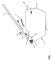
- the figure shows a part of the ventilation device according to the invention in one schematically illustrated section of a longitudinal section through the motor vehicle.
- the ventilation arrangement according to the invention is essentially a Hollow body formed body part 1 of the motor vehicle.
- the embodiment shown is the body part between the A-pillars of the Motor vehicle extending cross member 1.
- the lower part of the windshield 2 is on attached to this cross member 1 by means of an adhesive 4.
- the embodiment is the rest position of the wiper blades 3 of the wipers for the Windshield 2 above the fastening line 4 of the windshield 2.
- Air supply means not shown
- About the interior of the entire width of the motor vehicle extending cross member 1 can be the of Air supply air supplied to any position along the width of the Motor vehicle are fed to the lower end of the windshield 2.
- Air outlet openings 5 are provided in the cross member 1 for the ventilation air to exit educated. These openings can be designed as air nozzles or can Air nozzles can be inserted into the openings 5. Furthermore, the air outlet opening as a Slit or several slits can be formed.
- the air outlet openings 5 are in the the windshield 2 facing side 8 of the cross member 1 is formed so that the Ventilation air flows directly onto the lower part of the windshield 2 and then in can enter the interior of the motor vehicle. For this, the disc 2 closes facing part of the control panel 7 not adjacent to the disc 2, but lets a gap for the ventilation air to flow through.
- the Attachment 4 at the upper end of the side 8 facing the windshield 2 of the cross member 1 and the rest position of the wiper blades 3 is below this fastening line 4. Also in this case, the through the air outlet openings 5 escaping air directly to the rest position of the wiper blades 3 and also on the windshield 2 frozen wiper blades 3 very effectively de-iced become.
Landscapes
- Physics & Mathematics (AREA)
- Thermal Sciences (AREA)
- Engineering & Computer Science (AREA)
- Mechanical Engineering (AREA)
- Air-Conditioning For Vehicles (AREA)
- Motor Or Generator Cooling System (AREA)
Abstract
Description
Claims (8)
- Belüftungsanordnung für eine Scheibe, insbesondere Windschutzscheibe (2), eines Kraftfahrzeugs, die einen Luftkanal mit mindestens einer Luftaustrittsöffnung (5) zum Anströmen des unteren Teils der Scheibe mit Luft und Luftversorgungsmittel aufweist, durch die Luft dem Luftkanal zumindest während des Fahrbetriebs des Kraftfahrzeugs zuführbar ist,
dadurch gekennzeichnet,
daß der Luftkanal von einem als Hohlkörper ausgebildeten Karosserieteil (1) des Kraftfahrzeugs gebildet ist. - Belüftungsanordnung gemäß Anspruch 1,
dadurch gekennzeichnet,
daß die Scheibe die Windschutzscheibe (2) des Kraftfahrzeugs ist und daß das Karosserieteil (1) der zwischen den A-Säulen des Kraftfahrzeugs verlaufende Querträger ist, an dem der untere Rand der Windschutzscheibe (2) befestigt ist. - Belüftungsanordnung gemäß Anspruch 2,
dadurch gekennzeichnet,
daß die Windschutzscheibe (2) an einem unteren Teil einer der Scheibe (2) zugewandten Seite (8) des Querträgers (1) entlang einer Befestigungslinie (4) befestigt ist, und daß oberhalb der Befestigungslinie (4) die der Scheibe zugewandte Seite (8) des Querträgers (1) mindestens eine Luftaustrittsöffnung (5) zum Anströmen des unteren, oberhalb der Befestigungslinie der Scheibe (2) liegenden Teils der Scheibe (2) und zum Belüften des Innenraums des Kraftfahrzeugs aufweist. - Belüftungsanordnung gemäß Anspruch 2 oder 3,
dadurch gekennzeichnet,
daß die Windschutzscheibe (2) an einem unteren Teil einer der Scheibe (2) zugewandten Seite (8) des Querträgers (1) entlang einer Befestigungslinie (4) befestigt ist, und daß unterhalb der Befestigungslinie (4) die der Scheibe (2) zugewandte Seite (8) des Querträgers (1) mindestens eine Luftaustrittsöffnung (5) zum Anströmen des unterhalb der Befestigungslinie (4) der Scheibe (2) liegenden Teils der Scheibe (2) aufweist. - Belüftungsanordnung gemäß Anspruch 3 oder 4,
dadurch gekennzeichnet,
daß die der Scheibe (2) zugewandte Seite (8) des Querträgers (1) mehrere Luftaustrittsöffnungen (5) aufweist, die als Luftdüsen ausgebildet sind oder in die Luftdüsen eingesetzt sind. - Belüftungsanordnung gemäß Anspruch 3 oder 4,
dadurch gekennzeichnet,
daß die Luftaustrittsöffnung (5) als Schlitz ausgebildet ist. - Belüftungsanordnung gemäß einem der vorstehenden Ansprüche,
dadurch gekennzeichnet,
daß auf der Außenseite der Scheibe Wischblätter (3) aufliegen, deren Ruheposition in dem Bereich der Scheibe (2) ist, der von der mindestens einen Luftaustrittsöffnung (5) des Karosserieteils (1) mit Luft anströmbar ist. - Belüftungsanordnung gemäß einem der vorstehenden Ansprüche,
dadurch gekennzeichnet,
daß das Karosserieteil (1) eine Einströmöffnung (6) aufweist, durch die von den Luftversorgungsmitteln zugeführte Luft in das Karosserieteil (1) einströmen kann.
Applications Claiming Priority (2)
| Application Number | Priority Date | Filing Date | Title |
|---|---|---|---|
| DE19952158 | 1999-10-29 | ||
| DE19952158A DE19952158A1 (de) | 1999-10-29 | 1999-10-29 | Belüftungsanordnung für eine Scheibe eines Kraftfahrzeugs |
Publications (2)
| Publication Number | Publication Date |
|---|---|
| EP1095803A1 true EP1095803A1 (de) | 2001-05-02 |
| EP1095803B1 EP1095803B1 (de) | 2006-03-01 |
Family
ID=7927324
Family Applications (1)
| Application Number | Title | Priority Date | Filing Date |
|---|---|---|---|
| EP00122293A Expired - Lifetime EP1095803B1 (de) | 1999-10-29 | 2000-10-20 | Kraftfahrzeug mit einer Belüftungsanordnung |
Country Status (3)
| Country | Link |
|---|---|
| EP (1) | EP1095803B1 (de) |
| AT (1) | ATE318725T1 (de) |
| DE (2) | DE19952158A1 (de) |
Citations (6)
| Publication number | Priority date | Publication date | Assignee | Title |
|---|---|---|---|---|
| EP0073317A1 (de) * | 1981-08-25 | 1983-03-09 | Toyota Jidosha Kabushiki Kaisha | Schürzenhohlquerbalken für Motorfahrzeug |
| US4549471A (en) * | 1983-11-04 | 1985-10-29 | General Motors Corporation | Defroster system for use in motor vehicles |
| US4604946A (en) * | 1984-05-25 | 1986-08-12 | Nissan Motor Company, Limited | Structure of defroster nozzle for automotive vehicle |
| US4766805A (en) * | 1986-01-17 | 1988-08-30 | Mazda Motor Corporation | Windshield defroster system for vehicle |
| US4805522A (en) * | 1985-04-16 | 1989-02-21 | Honda Giken Kogyo Kabushiki Kaisha | Cross member structure for automobile |
| DE19648740C1 (de) * | 1996-11-25 | 1998-04-09 | Daimler Benz Ag | Defrostereinrichtung für eine Frontscheibe eines Kraftfahrzeuges |
Family Cites Families (2)
| Publication number | Priority date | Publication date | Assignee | Title |
|---|---|---|---|---|
| FR2049498A5 (de) * | 1969-06-11 | 1971-03-26 | Peugeot & Renault | |
| DE3017974A1 (de) * | 1980-05-10 | 1981-11-26 | Steyr-Daimler-Puch AG, 1010 Wien | Belueftungseinrichtung fuer windschutzscheiben von kraftfahrzeugen. |
-
1999
- 1999-10-29 DE DE19952158A patent/DE19952158A1/de not_active Withdrawn
-
2000
- 2000-10-20 EP EP00122293A patent/EP1095803B1/de not_active Expired - Lifetime
- 2000-10-20 AT AT00122293T patent/ATE318725T1/de not_active IP Right Cessation
- 2000-10-20 DE DE50012285T patent/DE50012285D1/de not_active Expired - Lifetime
Patent Citations (6)
| Publication number | Priority date | Publication date | Assignee | Title |
|---|---|---|---|---|
| EP0073317A1 (de) * | 1981-08-25 | 1983-03-09 | Toyota Jidosha Kabushiki Kaisha | Schürzenhohlquerbalken für Motorfahrzeug |
| US4549471A (en) * | 1983-11-04 | 1985-10-29 | General Motors Corporation | Defroster system for use in motor vehicles |
| US4604946A (en) * | 1984-05-25 | 1986-08-12 | Nissan Motor Company, Limited | Structure of defroster nozzle for automotive vehicle |
| US4805522A (en) * | 1985-04-16 | 1989-02-21 | Honda Giken Kogyo Kabushiki Kaisha | Cross member structure for automobile |
| US4766805A (en) * | 1986-01-17 | 1988-08-30 | Mazda Motor Corporation | Windshield defroster system for vehicle |
| DE19648740C1 (de) * | 1996-11-25 | 1998-04-09 | Daimler Benz Ag | Defrostereinrichtung für eine Frontscheibe eines Kraftfahrzeuges |
Also Published As
| Publication number | Publication date |
|---|---|
| ATE318725T1 (de) | 2006-03-15 |
| EP1095803B1 (de) | 2006-03-01 |
| DE19952158A1 (de) | 2001-05-03 |
| DE50012285D1 (de) | 2006-04-27 |
Similar Documents
| Publication | Publication Date | Title |
|---|---|---|
| DE4338685C1 (de) | Fahrzeugkarosserie | |
| EP2090449A2 (de) | Fahrzeug mit einer Klima- bzw. Lüftungsanlage | |
| EP2429862A1 (de) | Kraftfahrzeug | |
| WO2009003553A1 (de) | Kraftfahrzeug mit einer a-säule | |
| DE3634296C1 (de) | Vorrichtung zum Ableiten von Schmutzwasser von einer Scheibe eines Fahrzeugs,insbesondere eines Kraftfahrzeugs | |
| EP2479067B1 (de) | Strömungsoptimiertes Gehäuse an der Frontschiebe eines Kraftfahrzeugs | |
| DE102019109134A1 (de) | Einrichtung zum Entfernen von Regentropfen aus einem Bereich einer Fahrzeugscheibe, Fahrzeug sowie Verfahren | |
| DE19907390A1 (de) | Kraftfahrzeug mit Scheibenwischer | |
| DE4308036A1 (de) | A-Säule für ein Kraftfahrzeug | |
| DE102013010637A1 (de) | Belüftungseinrichtung für eine Scheibe eines Kraftwagens | |
| DE102009032604A1 (de) | Abdeckung für den Außenbereich der A-Säule eines Kraftfahrzeuges | |
| EP1095803A1 (de) | Belüftungsanordnung für eine Scheibe eines Kraftfahrzeugs | |
| DE4405926C2 (de) | Fahrzeugscheibenwischer | |
| DE102004012867B4 (de) | Scheibenwischer für die Scheibenwischeranlage an einem Fahrzeug | |
| DE3116628A1 (de) | Im heckbereich eines personenkraftfahrzeuges mit heckscheibe angeordneter abweiser fuer schmutz, regen und dgl. | |
| DE19948223B4 (de) | Fahrgastzelle eines Fahrzeugs | |
| DE10130381A1 (de) | Wischerarm, Wischblatt und Wischvorrichtung, insbesondere für Scheiben von Kraftfahrzeugen | |
| DE102013010557A1 (de) | Belüftungseinrichtung für eine Scheibe eines Kraftwagens | |
| DE3923947A1 (de) | Aussenspiegel fuer kraftfahrzeuge | |
| DE3631467C2 (de) | Luftleitvorrichtung für Vollheck-Kraftfahrzeuge | |
| DE2943887A1 (de) | Scheibenwaschvorrichtung fuer eine fahrzeugscheibe | |
| DE19523760C2 (de) | Vorrichtung zum Reinigen einer Scheibe, insbesondere einer Frontscheibe eines Fahrzeuges | |
| DE10326417B4 (de) | Anordnung einer Seitenscheibe eines Kraftfahrzeugs | |
| DE10115557A1 (de) | Vorrichtung zum Beeinflussen eines gegen die Windschutzscheibe eines Fahrzeugs gerichteten Luftstroms | |
| DE2912612A1 (de) | Luftstroemungsabweiser |
Legal Events
| Date | Code | Title | Description |
|---|---|---|---|
| PUAI | Public reference made under article 153(3) epc to a published international application that has entered the european phase |
Free format text: ORIGINAL CODE: 0009012 |
|
| AK | Designated contracting states |
Kind code of ref document: A1 Designated state(s): AT BE CH CY DE DK ES FI FR GB GR IE IT LI LU MC NL PT SE |
|
| AX | Request for extension of the european patent |
Free format text: AL;LT;LV;MK;RO;SI |
|
| 17P | Request for examination filed |
Effective date: 20011102 |
|
| AKX | Designation fees paid |
Free format text: AT BE CH CY DE DK ES FI FR GB GR IE IT LI LU MC NL PT SE |
|
| 17Q | First examination report despatched |
Effective date: 20040329 |
|
| RTI1 | Title (correction) |
Free format text: MOTOR VEHICLE WITH VENTILATING ASSEMBLY |
|
| GRAP | Despatch of communication of intention to grant a patent |
Free format text: ORIGINAL CODE: EPIDOSNIGR1 |
|
| GRAS | Grant fee paid |
Free format text: ORIGINAL CODE: EPIDOSNIGR3 |
|
| GRAA | (expected) grant |
Free format text: ORIGINAL CODE: 0009210 |
|
| AK | Designated contracting states |
Kind code of ref document: B1 Designated state(s): AT BE CH CY DE DK ES FI FR GB GR IE IT LI LU MC NL PT SE |
|
| PG25 | Lapsed in a contracting state [announced via postgrant information from national office to epo] |
Ref country code: IT Free format text: LAPSE BECAUSE OF FAILURE TO SUBMIT A TRANSLATION OF THE DESCRIPTION OR TO PAY THE FEE WITHIN THE PRESCRIBED TIME-LIMIT;WARNING: LAPSES OF ITALIAN PATENTS WITH EFFECTIVE DATE BEFORE 2007 MAY HAVE OCCURRED AT ANY TIME BEFORE 2007. THE CORRECT EFFECTIVE DATE MAY BE DIFFERENT FROM THE ONE RECORDED. Effective date: 20060301 Ref country code: NL Free format text: LAPSE BECAUSE OF FAILURE TO SUBMIT A TRANSLATION OF THE DESCRIPTION OR TO PAY THE FEE WITHIN THE PRESCRIBED TIME-LIMIT Effective date: 20060301 Ref country code: IE Free format text: LAPSE BECAUSE OF FAILURE TO SUBMIT A TRANSLATION OF THE DESCRIPTION OR TO PAY THE FEE WITHIN THE PRESCRIBED TIME-LIMIT Effective date: 20060301 Ref country code: GB Free format text: LAPSE BECAUSE OF FAILURE TO SUBMIT A TRANSLATION OF THE DESCRIPTION OR TO PAY THE FEE WITHIN THE PRESCRIBED TIME-LIMIT Effective date: 20060301 Ref country code: FI Free format text: LAPSE BECAUSE OF FAILURE TO SUBMIT A TRANSLATION OF THE DESCRIPTION OR TO PAY THE FEE WITHIN THE PRESCRIBED TIME-LIMIT Effective date: 20060301 |
|
| REG | Reference to a national code |
Ref country code: GB Ref legal event code: FG4D Free format text: NOT ENGLISH |
|
| REG | Reference to a national code |
Ref country code: CH Ref legal event code: EP |
|
| REG | Reference to a national code |
Ref country code: IE Ref legal event code: FG4D Free format text: LANGUAGE OF EP DOCUMENT: GERMAN |
|
| REF | Corresponds to: |
Ref document number: 50012285 Country of ref document: DE Date of ref document: 20060427 Kind code of ref document: P |
|
| PG25 | Lapsed in a contracting state [announced via postgrant information from national office to epo] |
Ref country code: SE Free format text: LAPSE BECAUSE OF FAILURE TO SUBMIT A TRANSLATION OF THE DESCRIPTION OR TO PAY THE FEE WITHIN THE PRESCRIBED TIME-LIMIT Effective date: 20060601 Ref country code: DK Free format text: LAPSE BECAUSE OF FAILURE TO SUBMIT A TRANSLATION OF THE DESCRIPTION OR TO PAY THE FEE WITHIN THE PRESCRIBED TIME-LIMIT Effective date: 20060601 |
|
| PG25 | Lapsed in a contracting state [announced via postgrant information from national office to epo] |
Ref country code: ES Free format text: LAPSE BECAUSE OF FAILURE TO SUBMIT A TRANSLATION OF THE DESCRIPTION OR TO PAY THE FEE WITHIN THE PRESCRIBED TIME-LIMIT Effective date: 20060612 |
|
| PG25 | Lapsed in a contracting state [announced via postgrant information from national office to epo] |
Ref country code: PT Free format text: LAPSE BECAUSE OF FAILURE TO SUBMIT A TRANSLATION OF THE DESCRIPTION OR TO PAY THE FEE WITHIN THE PRESCRIBED TIME-LIMIT Effective date: 20060801 |
|
| NLV1 | Nl: lapsed or annulled due to failure to fulfill the requirements of art. 29p and 29m of the patents act | ||
| GBV | Gb: ep patent (uk) treated as always having been void in accordance with gb section 77(7)/1977 [no translation filed] |
Effective date: 20060301 |
|
| REG | Reference to a national code |
Ref country code: IE Ref legal event code: FD4D |
|
| PG25 | Lapsed in a contracting state [announced via postgrant information from national office to epo] |
Ref country code: CH Free format text: LAPSE BECAUSE OF NON-PAYMENT OF DUE FEES Effective date: 20061031 Ref country code: LI Free format text: LAPSE BECAUSE OF NON-PAYMENT OF DUE FEES Effective date: 20061031 Ref country code: MC Free format text: LAPSE BECAUSE OF NON-PAYMENT OF DUE FEES Effective date: 20061031 |
|
| PLBE | No opposition filed within time limit |
Free format text: ORIGINAL CODE: 0009261 |
|
| STAA | Information on the status of an ep patent application or granted ep patent |
Free format text: STATUS: NO OPPOSITION FILED WITHIN TIME LIMIT |
|
| 26N | No opposition filed |
Effective date: 20061204 |
|
| EN | Fr: translation not filed | ||
| REG | Reference to a national code |
Ref country code: CH Ref legal event code: PL |
|
| BERE | Be: lapsed |
Owner name: VOLKSWAGEN A.G. Effective date: 20061031 |
|
| PG25 | Lapsed in a contracting state [announced via postgrant information from national office to epo] |
Ref country code: AT Free format text: LAPSE BECAUSE OF NON-PAYMENT OF DUE FEES Effective date: 20061020 |
|
| PG25 | Lapsed in a contracting state [announced via postgrant information from national office to epo] |
Ref country code: GR Free format text: LAPSE BECAUSE OF FAILURE TO SUBMIT A TRANSLATION OF THE DESCRIPTION OR TO PAY THE FEE WITHIN THE PRESCRIBED TIME-LIMIT Effective date: 20060602 |
|
| PG25 | Lapsed in a contracting state [announced via postgrant information from national office to epo] |
Ref country code: LU Free format text: LAPSE BECAUSE OF NON-PAYMENT OF DUE FEES Effective date: 20061020 |
|
| PG25 | Lapsed in a contracting state [announced via postgrant information from national office to epo] |
Ref country code: CY Free format text: LAPSE BECAUSE OF FAILURE TO SUBMIT A TRANSLATION OF THE DESCRIPTION OR TO PAY THE FEE WITHIN THE PRESCRIBED TIME-LIMIT Effective date: 20060301 Ref country code: FR Free format text: LAPSE BECAUSE OF FAILURE TO SUBMIT A TRANSLATION OF THE DESCRIPTION OR TO PAY THE FEE WITHIN THE PRESCRIBED TIME-LIMIT Effective date: 20060301 |
|
| PG25 | Lapsed in a contracting state [announced via postgrant information from national office to epo] |
Ref country code: BE Free format text: LAPSE BECAUSE OF FAILURE TO SUBMIT A TRANSLATION OF THE DESCRIPTION OR TO PAY THE FEE WITHIN THE PRESCRIBED TIME-LIMIT Effective date: 20061031 |
|
| PGFP | Annual fee paid to national office [announced via postgrant information from national office to epo] |
Ref country code: DE Payment date: 20121031 Year of fee payment: 13 |
|
| REG | Reference to a national code |
Ref country code: DE Ref legal event code: R119 Ref document number: 50012285 Country of ref document: DE Effective date: 20140501 |
|
| PG25 | Lapsed in a contracting state [announced via postgrant information from national office to epo] |
Ref country code: DE Free format text: LAPSE BECAUSE OF NON-PAYMENT OF DUE FEES Effective date: 20140501 |