EP1095802A1 - Luftsteueranordnung für eine Ventilation, Heizung und/oder Klimaanlage eines Kraftfahrzeugs - Google Patents
Luftsteueranordnung für eine Ventilation, Heizung und/oder Klimaanlage eines Kraftfahrzeugs Download PDFInfo
- Publication number
- EP1095802A1 EP1095802A1 EP00122590A EP00122590A EP1095802A1 EP 1095802 A1 EP1095802 A1 EP 1095802A1 EP 00122590 A EP00122590 A EP 00122590A EP 00122590 A EP00122590 A EP 00122590A EP 1095802 A1 EP1095802 A1 EP 1095802A1
- Authority
- EP
- European Patent Office
- Prior art keywords
- axis
- housing
- flap
- shutter
- windows
- Prior art date
- Legal status (The legal status is an assumption and is not a legal conclusion. Google has not performed a legal analysis and makes no representation as to the accuracy of the status listed.)
- Granted
Links
Images


Classifications
-
- B—PERFORMING OPERATIONS; TRANSPORTING
- B60—VEHICLES IN GENERAL
- B60H—ARRANGEMENTS OF HEATING, COOLING, VENTILATING OR OTHER AIR-TREATING DEVICES SPECIALLY ADAPTED FOR PASSENGER OR GOODS SPACES OF VEHICLES
- B60H1/00—Heating, cooling or ventilating [HVAC] devices
- B60H1/00642—Control systems or circuits; Control members or indication devices for heating, cooling or ventilating devices
- B60H1/00664—Construction or arrangement of damper doors
- B60H1/00671—Damper doors moved by rotation; Grilles
- B60H1/00685—Damper doors moved by rotation; Grilles the door being a rotating disc or cylinder or part thereof
-
- B—PERFORMING OPERATIONS; TRANSPORTING
- B60—VEHICLES IN GENERAL
- B60H—ARRANGEMENTS OF HEATING, COOLING, VENTILATING OR OTHER AIR-TREATING DEVICES SPECIALLY ADAPTED FOR PASSENGER OR GOODS SPACES OF VEHICLES
- B60H1/00—Heating, cooling or ventilating [HVAC] devices
- B60H1/00642—Control systems or circuits; Control members or indication devices for heating, cooling or ventilating devices
- B60H1/00664—Construction or arrangement of damper doors
- B60H2001/00714—Details of seals of damper doors
Definitions
- the invention relates to a device for distributing a flow. air in a ventilation, heating and / or installation air conditioning of a motor vehicle interior.
- a device comprising a shutter rotatably mounted in a housing provided with a first and a second window communicating with first and second conduits, respectively.
- This box includes by elsewhere an opening communicating with a third conduit.
- the shutter whose axis of rotation is distant from the windows above, can selectively close the first or the second window to circulate an air flow between the third conduit and the second or first window.
- the flap rests on a wall of the housing, generally provided with an opening for communication with the aforementioned third conduit, which causes friction of the flap against this wall and, if if necessary, deterioration of the flap and / or of the wall.
- the present invention improves the situation.
- a distribution device of the type aforementioned comprising a partition formed in the bottom of the housing and provided with at least one opening for communication with the third leads.
- the device further comprises shutter support means, formed of a plurality of star branches starting substantially from a point of the axis of rotation of the flap and each comprising a end in contact with the aforementioned partition.
- the support means are produced under the shape of a tripod resting on the partition and comprising a central part provided with a recess suitable for accommodating rotation of an axis of the shutter.
- the aforementioned branches have, in a cross-sectional view and opposite the shutter, a profile substantially convex, preferably U-shaped, which avoids disturbances in the air flow circulating in The box.
- the housing is produced at least in part in the general form of a hollow cylinder, provided with the first and second windows, while that the aforementioned partition forms a base of the cylinder.
- the blind aforementioned is then a drum shutter, produced in the form general of a portion of hollow cylinder. Its general axis and its axis of rotation are preferably substantially parallel to the axis of the housing.
- cylinder is to be taken here in the broad sense and thus relates to any surface generated by the rotation of a generating curve around the axis of the cylinder. It applies so as well to a straight cylinder as to a cone or even a sphere.
- the axis of rotation of the flap is distant from the axis of the cylinder portion forming the shutter, which allows the windows to be sealed mentioned above.
- the shutter comprises, according to a second form of embodiment, at least one wall on a lateral end of the cylinder portion, which extends outward from the portion, preferably substantially in line with a portion radius.
- one of the windows of the housing has a general trapezoid shape while said flap has a homologous form.
- Figure 1 We first refer to Figure 1 to describe a device for distributing an air flow from an installation ventilation, heating and / or air conditioning of the passenger compartment of a motor vehicle, according to the invention.
- the device comprises a housing 3 of general shape substantially hollow cylindrical and having openings (or windows) 30 and 31 which communicate respectively with outside air and recirculated air inlet ducts (from initially from the passenger compartment).
- the housing 3 comprises, substantially at the base of the cylinder, a partition 32 provided with a opening 33 and forming a deflecting ferrule communicating with a vehicle interior ventilation duct (not represented).
- the housing 3 rotates a flap 2, around the axis x-x, substantially parallel to the axis of the cylinder formed by the box 3.
- the shutter 2 is a drum shutter comprising a portion of hollow cylinder 20 which can pivot around the axis X-X to be opposite the openings 30 and 31 of the housing 3, with a view to closing or opening them.
- the angular position of the flap 2 makes it possible to manage the proportion of outside air flow or recirculated air flow that admits the housing 3 for the supply of the passenger compartment.
- the air admitted into the housing 3 is routed in a ventilation unit fitted with a PUL blower, to then be evacuated to the ventilation duct of the aforementioned passenger compartment.
- drum shutters for such distribution have a drum wall 20 which extends substantially over the entire length of the housing 3.
- the flap 2 in rotation scrapes the partition 32 of the deflection ring above, which leads to a state of wear of the ferrule and / or of the shutter.
- the shutter 2 extends over only part of the height of the housing 3 leaving a gap between the portion of the shutter cylinder and the deflecting ferrule in the bottom of the housing.
- These support means are preferably made in the form of a tripod with three branches 10, 11 and 12 which extend from a central part 13 which the axis of rotation XX of the flap 2 crosses. The ends of these three branches rest on the partition 32 of the deflector ring 33.
- the flap 2 comprises, for its part, a reinforcing and stiffening rib produced in the form of a splint 21, as well as an open flange 22 (FIGS.
- branches 10, 11 and 12 of the tripod 1 are advantageously inverted U-shaped, which prevents disturbances in the air flow in the housing 3 towards the PUL blower.
- the shutter 2 is formed by a portion of cylinder 20, of axis parallel to the axis of rotation X-X, between two flanges 22 and 22 '( Figures 3A and 3B).
- the flange 22 is open to let the flow pass through the housing 3.
- the splint 21 can advantageously be of U-shaped section overturned to avoid disturbing the air flow circulating in The box.
- Part 2 includes, on either side of the cylinder portion 20, two side walls 24A and 24B, in the extension of a radius extending from the X-X axis towards the outer surface of the cylinder portion 20.
- these walls 24A and 24B contribute to a watertight docking of the shutter against windows 30 and 31 of communication of the housing 3 with the outside air ducts and recirculated air.
- the cylinder portion of the flap has in addition inclined faces 25 and 26 to promote sealing above against the windows of the housing 3.
- the shutter 2 comprises a portion of cylinder whose axis is offset from its axis of rotation X-X.
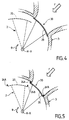
- the reference ⁇ in FIG. 4 designates the angular travel of the axis of the cylinder portion 20 of the flap between an open position (shown in line dotted line) and a position for closing window 30 of the housing 3.
- the portion of cylinder 20, of axis offset by relative to the axis of rotation X-X of the flap 22 comes to close sealingly the window 30, coming to bear against the walls which delimit the window 30.
- the flap 2 comprises, on either side of the cylinder portion 20, walls 24A and 24B which extend towards the outside of the portion of cylinder, coming into contact with the walls which delimit the window 30 of the housing 3.
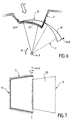
- the flap 2 comprises, according to a third embodiment, a portion of cylinder 20 of substantially trapezoidal ( Figure 7) to fit into an opening of homologous shape 31 arranged in the housing 3, for communication with one of the air ducts outside or recirculated air.
- a portion shape cylinder 20 advantageously provides a closure sealed from the communication 31 with the recirculated air duct, in particular.
- this latter embodiment can be combined with the previous modes for watertight closures of both outside and recirculated air ducts. It can be provided on the walls delimiting the openings 30 and 31 a foam or a molded lip to promote the tightness described above.
- the support means 1 of the shutter 2 allow, according to one of the major advantages which the present invention provides, to substantially raise the flap in the housing 3, which allows to provide a shutter 2 whose portion of cylinder 20 can be of a shape chosen to close so waterproof the communication windows 30 and 31 of the housing 3.
- the tripod shown in the figure 1 may include a number of branches other than three, for example a number greater than three.
- the U-shape of the tripod branches shown in the figure 2 above is given by way of example. Although advantageous, the cross-sectional shape of the branches may be different.
- the housing as well as the flap housed in the housing, have shapes general cylindrical straight, hollow.
- these shapes are hollow conical or hollow spherical, the flap retaining a shape substantially homologous to that of the case.
- the present invention finds an interesting application in distribution of outside air flow and recirculated air flow in a distribution box communicating with a conduit supplying a passenger compartment of a motor vehicle. She finds other applications, in particular to a mixing room of a ventilation and heating system and / or air conditioning of the passenger compartment of such a vehicle, by example in a device comprising a housing accommodating rotation of a mixing flap upstream of the mixing chamber.
- the housing described in the example above does not comprises an opening 33 arranged in its base. he can however, one or more openings must be provided in the housing, depending on the intended application.
- windows described above constitute air inlets, while the opening 33 forms the air outlet of the housing.
- the opening may form the air inlet and the aforementioned windows, air outlets.
- it can be provided a box provided with more than two windows, forming for example air outlets, if desired to feed several pipes at the same time.
- the term "conduits" (with which the inputs / outputs of the housing) is to be taken here in the broad sense. It also concerns a space delimited by partitions airtight, that an opening for an outside air intake for example, or a mixing chamber, communicating itself with other conduits.
Landscapes
- Physics & Mathematics (AREA)
- Thermal Sciences (AREA)
- Engineering & Computer Science (AREA)
- Mechanical Engineering (AREA)
- Air-Conditioning For Vehicles (AREA)
- Passenger Equipment (AREA)
- Vehicle Step Arrangements And Article Storage (AREA)
Applications Claiming Priority (2)
| Application Number | Priority Date | Filing Date | Title |
|---|---|---|---|
| FR9913450 | 1999-10-27 | ||
| FR9913450A FR2800328B1 (fr) | 1999-10-27 | 1999-10-27 | Dispositif de distribution perfectionne d'un flux d'air dans une installation de ventilation, chauffage et/ou climatisation d'un vehicule automobile |
Publications (2)
| Publication Number | Publication Date |
|---|---|
| EP1095802A1 true EP1095802A1 (de) | 2001-05-02 |
| EP1095802B1 EP1095802B1 (de) | 2008-08-27 |
Family
ID=9551432
Family Applications (1)
| Application Number | Title | Priority Date | Filing Date |
|---|---|---|---|
| EP20000122590 Expired - Lifetime EP1095802B1 (de) | 1999-10-27 | 2000-10-17 | Luftsteueranordnung für eine Ventilation, Heizung und/oder Klimaanlage eines Kraftfahrzeugs |
Country Status (6)
| Country | Link |
|---|---|
| EP (1) | EP1095802B1 (de) |
| BR (1) | BR0005064A (de) |
| DE (1) | DE60040046D1 (de) |
| ES (1) | ES2312318T3 (de) |
| FR (1) | FR2800328B1 (de) |
| TR (1) | TR200003119A1 (de) |
Cited By (8)
| Publication number | Priority date | Publication date | Assignee | Title |
|---|---|---|---|---|
| EP1510378A2 (de) * | 2003-08-25 | 2005-03-02 | Behr GmbH & Co. KG | Trommelklappe |
| DE10352533A1 (de) * | 2003-11-07 | 2005-06-02 | Behr Gmbh & Co. Kg | Trommelklappe |
| DE102005041725A1 (de) * | 2005-09-01 | 2007-03-08 | Behr Gmbh & Co. Kg | Luftstromschalteinrichtung |
| EP2030818A1 (de) * | 2007-08-29 | 2009-03-04 | Valeo Systemes Thermiques | Kraftfahrzeugklimaanlagemischluftstromverteilvorrichtung |
| FR2929558A1 (fr) * | 2008-04-03 | 2009-10-09 | Valeo Systemes Thermiques | Organe de mixage d'air du type volet-tambour et installation de chauffage, de ventilation et/ou de climatisation equipee d'un tel organe de mixage d'air. |
| EP2402183A1 (de) | 2010-06-29 | 2012-01-04 | Behr France Rouffach SAS | Kraftfahrzeugklimaanlage |
| US8091623B2 (en) | 2004-10-01 | 2012-01-10 | Behr Gmbh & Co. Kg | Air mixer vent |
| CN111845251A (zh) * | 2019-04-30 | 2020-10-30 | 马勒国际有限公司 | 用于密封功能单元接口的装置 |
Families Citing this family (1)
| Publication number | Priority date | Publication date | Assignee | Title |
|---|---|---|---|---|
| FR2993503B1 (fr) * | 2012-07-20 | 2015-01-30 | Valeo Systemes Thermiques | Volet d'obturation pour extremite de conduit d'air dans un systeme de chauffage ou de climatisation de vehicule automobile |
Citations (4)
| Publication number | Priority date | Publication date | Assignee | Title |
|---|---|---|---|---|
| JPS6060026A (ja) * | 1983-09-13 | 1985-04-06 | Nissan Motor Co Ltd | 自動車用送風装置 |
| DE19753617A1 (de) * | 1996-12-23 | 1998-06-25 | Valeo Climatisation | Vorrichtung zur Heizung, Belüftung und/oder Klimatisierung, insbesondere für den Fahrgastraum eines Kraftfahrzeugs |
| JPH10315744A (ja) * | 1997-05-21 | 1998-12-02 | Calsonic Corp | 自動車用空気調和装置のインテークユニット |
| DE19733052A1 (de) * | 1997-07-31 | 1999-02-04 | Behr Gmbh & Co | Lufteintritt für eine Heizungs- oder Klimaanlage eines Kraftfahrzeuges |
-
1999
- 1999-10-27 FR FR9913450A patent/FR2800328B1/fr not_active Expired - Lifetime
-
2000
- 2000-10-17 DE DE60040046T patent/DE60040046D1/de not_active Expired - Lifetime
- 2000-10-17 EP EP20000122590 patent/EP1095802B1/de not_active Expired - Lifetime
- 2000-10-17 ES ES00122590T patent/ES2312318T3/es not_active Expired - Lifetime
- 2000-10-25 TR TR2000/03119A patent/TR200003119A1/xx unknown
- 2000-10-26 BR BR0005064A patent/BR0005064A/pt not_active IP Right Cessation
Patent Citations (4)
| Publication number | Priority date | Publication date | Assignee | Title |
|---|---|---|---|---|
| JPS6060026A (ja) * | 1983-09-13 | 1985-04-06 | Nissan Motor Co Ltd | 自動車用送風装置 |
| DE19753617A1 (de) * | 1996-12-23 | 1998-06-25 | Valeo Climatisation | Vorrichtung zur Heizung, Belüftung und/oder Klimatisierung, insbesondere für den Fahrgastraum eines Kraftfahrzeugs |
| JPH10315744A (ja) * | 1997-05-21 | 1998-12-02 | Calsonic Corp | 自動車用空気調和装置のインテークユニット |
| DE19733052A1 (de) * | 1997-07-31 | 1999-02-04 | Behr Gmbh & Co | Lufteintritt für eine Heizungs- oder Klimaanlage eines Kraftfahrzeuges |
Non-Patent Citations (2)
| Title |
|---|
| PATENT ABSTRACTS OF JAPAN vol. 009, no. 194 (M - 403) 10 August 1985 (1985-08-10) * |
| PATENT ABSTRACTS OF JAPAN vol. 1999, no. 03 31 March 1999 (1999-03-31) * |
Cited By (13)
| Publication number | Priority date | Publication date | Assignee | Title |
|---|---|---|---|---|
| DE10339337A1 (de) * | 2003-08-25 | 2005-04-14 | Behr Gmbh & Co. Kg | Trommelklappe |
| EP1510378A3 (de) * | 2003-08-25 | 2005-11-16 | Behr GmbH & Co. KG | Trommelklappe |
| EP1510378A2 (de) * | 2003-08-25 | 2005-03-02 | Behr GmbH & Co. KG | Trommelklappe |
| US7985124B2 (en) | 2003-11-07 | 2011-07-26 | Behr Gmbh & Co. Kg | Drum-type valve |
| DE10352533A1 (de) * | 2003-11-07 | 2005-06-02 | Behr Gmbh & Co. Kg | Trommelklappe |
| US8091623B2 (en) | 2004-10-01 | 2012-01-10 | Behr Gmbh & Co. Kg | Air mixer vent |
| DE102005041725A1 (de) * | 2005-09-01 | 2007-03-08 | Behr Gmbh & Co. Kg | Luftstromschalteinrichtung |
| FR2920511A1 (fr) * | 2007-08-29 | 2009-03-06 | Valeo Systemes Thermiques | Dispositif de distribution d'un flux d'air mixe, notamment pour une installation de chauffage, de ventilation et/ou de climatisation d'un vehicule automobile |
| EP2030818A1 (de) * | 2007-08-29 | 2009-03-04 | Valeo Systemes Thermiques | Kraftfahrzeugklimaanlagemischluftstromverteilvorrichtung |
| FR2929558A1 (fr) * | 2008-04-03 | 2009-10-09 | Valeo Systemes Thermiques | Organe de mixage d'air du type volet-tambour et installation de chauffage, de ventilation et/ou de climatisation equipee d'un tel organe de mixage d'air. |
| CN101618670B (zh) * | 2008-04-03 | 2013-12-11 | 法雷奥热系统公司 | 空气混合装置和配备它的采暖、通风和/或空气调节设备 |
| EP2402183A1 (de) | 2010-06-29 | 2012-01-04 | Behr France Rouffach SAS | Kraftfahrzeugklimaanlage |
| CN111845251A (zh) * | 2019-04-30 | 2020-10-30 | 马勒国际有限公司 | 用于密封功能单元接口的装置 |
Also Published As
| Publication number | Publication date |
|---|---|
| TR200003119A1 (tr) | 2001-05-21 |
| EP1095802B1 (de) | 2008-08-27 |
| FR2800328A1 (fr) | 2001-05-04 |
| ES2312318T3 (es) | 2009-03-01 |
| DE60040046D1 (de) | 2008-10-09 |
| FR2800328B1 (fr) | 2002-01-11 |
| BR0005064A (pt) | 2001-06-12 |
Similar Documents
| Publication | Publication Date | Title |
|---|---|---|
| EP1288031B1 (de) | Vorrichtung zur Erzeugung einer temperaturgeregelten Luftströmung für einen Kraftfahrzeugfahrgastraum und Heizungs- und/oder Klimaanlage mit einer solchen Sicherungsvorrichtung | |
| FR2659603A1 (fr) | Dispositif de chauffage et de ventilation de l'habitacle d'un vehicule automobile. | |
| EP1514707B1 (de) | Verbesserte Lufttemperatursteuerung einer Heiz- und/oder Klimaanlage einer Fahrgastzelle | |
| EP1095802A1 (de) | Luftsteueranordnung für eine Ventilation, Heizung und/oder Klimaanlage eines Kraftfahrzeugs | |
| FR2862911A1 (fr) | Dispositif de chauffage-ventilation et/ou climatisation d'un habitacle de vehicule avec reglage de temperature par zones | |
| EP0709241B1 (de) | Heizungs- und/oder Belüftungsanlage eines Fahrzeuginnenraumes | |
| EP2243646A1 (de) | Gehäuse zur Wärmebehandlung für die Wärmebehandlung eines Luftstroms | |
| FR2720693A1 (fr) | Dispositif de chauffage et/ou d'aération de l'habitacle d'un véhicule. | |
| EP0266230A1 (de) | Mischklappe für Fahrzeugklimaanlagen und ähnliche Anwendungen | |
| FR2777512A1 (fr) | Boitier d'admission d'air pour une installation de chauffage et/ou climatisation de vehicule automobile | |
| WO2020174146A1 (fr) | Installation de chauffage et/ou ventilation et/ou climatisation comportant un volet de mixage avec déflecteur | |
| FR2713154A1 (fr) | Dispositif de distribution pour une installation de climatisation de véhicule automobile. | |
| FR2778151A1 (fr) | Dispositif repartiteur d'un flux d'air dans un habitacle, notamment d'un vehicule automobile | |
| FR2783205A1 (fr) | Organe de commande pour un dispositif de distribution d'air destine a des compartiments des passagers | |
| EP1514708B1 (de) | Heiz und/oder Klimatiserungsvorrichtung für Fahrzeuginnenraum, mit hoch entwickelter aerothermischer Regelung | |
| FR2757455A1 (fr) | Dispositif de chauffage/ventilation et/ou climatisation, notamment pour l'habitacle d'un vehicule automobile | |
| EP1065080B1 (de) | Gebläseeinheit, optimiert in Grösse und Zugänglichkeit | |
| FR2798322A1 (fr) | Dispositif de chauffage et/ou climatisation de vehicule automobile a distribution amelioree | |
| FR2728515A1 (fr) | Dispositif de distribution d'air dans l'habitacle d'un vehicule | |
| FR2746714A1 (fr) | Dispositif de chauffage et/ou climatisation de l'habitacle d'un vehicule automobile | |
| FR2761011A1 (fr) | Dispositif de chauffage-ventilation et/ou climatisation d'un vehicule, comprenant une commande par volet | |
| FR2786134A1 (fr) | Dispositif de chauffage-ventilation de l'habitacle d'un vehicule | |
| FR2761014A1 (fr) | Dispositif perfectionne de gestion de flux d'air exterieur et recircule, notamment pour une installation de chauffage et/ou climatisation de vehicule automobile | |
| EP4255512A1 (de) | Diffusor zur befestigung an einem lüftungsgitter zur gesteuerten abgabe eines lufterfrischers | |
| FR2771967A1 (fr) | Dispositif de chauffage et/ou climatisation de vehicule automobile, avec aerations laterales |
Legal Events
| Date | Code | Title | Description |
|---|---|---|---|
| PUAI | Public reference made under article 153(3) epc to a published international application that has entered the european phase |
Free format text: ORIGINAL CODE: 0009012 |
|
| AK | Designated contracting states |
Kind code of ref document: A1 Designated state(s): DE ES GB IT |
|
| AX | Request for extension of the european patent |
Free format text: AL;LT;LV;MK;RO;SI |
|
| 17P | Request for examination filed |
Effective date: 20011030 |
|
| AKX | Designation fees paid |
Free format text: DE ES GB IT |
|
| 17Q | First examination report despatched |
Effective date: 20061017 |
|
| RAP1 | Party data changed (applicant data changed or rights of an application transferred) |
Owner name: VALEO SYSTEMES THERMIQUES |
|
| GRAP | Despatch of communication of intention to grant a patent |
Free format text: ORIGINAL CODE: EPIDOSNIGR1 |
|
| GRAS | Grant fee paid |
Free format text: ORIGINAL CODE: EPIDOSNIGR3 |
|
| GRAA | (expected) grant |
Free format text: ORIGINAL CODE: 0009210 |
|
| AK | Designated contracting states |
Kind code of ref document: B1 Designated state(s): DE ES GB IT |
|
| REG | Reference to a national code |
Ref country code: GB Ref legal event code: FG4D Free format text: NOT ENGLISH |
|
| REF | Corresponds to: |
Ref document number: 60040046 Country of ref document: DE Date of ref document: 20081009 Kind code of ref document: P |
|
| REG | Reference to a national code |
Ref country code: ES Ref legal event code: FG2A Ref document number: 2312318 Country of ref document: ES Kind code of ref document: T3 |
|
| PLBE | No opposition filed within time limit |
Free format text: ORIGINAL CODE: 0009261 |
|
| STAA | Information on the status of an ep patent application or granted ep patent |
Free format text: STATUS: NO OPPOSITION FILED WITHIN TIME LIMIT |
|
| GBPC | Gb: european patent ceased through non-payment of renewal fee |
Effective date: 20081127 |
|
| 26N | No opposition filed |
Effective date: 20090528 |
|
| PG25 | Lapsed in a contracting state [announced via postgrant information from national office to epo] |
Ref country code: GB Free format text: LAPSE BECAUSE OF NON-PAYMENT OF DUE FEES Effective date: 20081127 |
|
| PGFP | Annual fee paid to national office [announced via postgrant information from national office to epo] |
Ref country code: IT Payment date: 20161011 Year of fee payment: 17 |
|
| PG25 | Lapsed in a contracting state [announced via postgrant information from national office to epo] |
Ref country code: IT Free format text: LAPSE BECAUSE OF NON-PAYMENT OF DUE FEES Effective date: 20171017 |
|
| PGFP | Annual fee paid to national office [announced via postgrant information from national office to epo] |
Ref country code: DE Payment date: 20191009 Year of fee payment: 20 |
|
| PGFP | Annual fee paid to national office [announced via postgrant information from national office to epo] |
Ref country code: ES Payment date: 20191119 Year of fee payment: 20 |
|
| REG | Reference to a national code |
Ref country code: DE Ref legal event code: R071 Ref document number: 60040046 Country of ref document: DE |
|
| REG | Reference to a national code |
Ref country code: ES Ref legal event code: FD2A Effective date: 20210129 |
|
| PG25 | Lapsed in a contracting state [announced via postgrant information from national office to epo] |
Ref country code: ES Free format text: LAPSE BECAUSE OF EXPIRATION OF PROTECTION Effective date: 20201018 |