EP2402183A1 - Kraftfahrzeugklimaanlage - Google Patents
Kraftfahrzeugklimaanlage Download PDFInfo
- Publication number
- EP2402183A1 EP2402183A1 EP10290350A EP10290350A EP2402183A1 EP 2402183 A1 EP2402183 A1 EP 2402183A1 EP 10290350 A EP10290350 A EP 10290350A EP 10290350 A EP10290350 A EP 10290350A EP 2402183 A1 EP2402183 A1 EP 2402183A1
- Authority
- EP
- European Patent Office
- Prior art keywords
- flap
- conditioning system
- air conditioning
- air
- fresh air
- Prior art date
- Legal status (The legal status is an assumption and is not a legal conclusion. Google has not performed a legal analysis and makes no representation as to the accuracy of the status listed.)
- Granted
Links
Images

Classifications
-
- B—PERFORMING OPERATIONS; TRANSPORTING
- B60—VEHICLES IN GENERAL
- B60H—ARRANGEMENTS OF HEATING, COOLING, VENTILATING OR OTHER AIR-TREATING DEVICES SPECIALLY ADAPTED FOR PASSENGER OR GOODS SPACES OF VEHICLES
- B60H1/00—Heating, cooling or ventilating [HVAC] devices
- B60H1/00642—Control systems or circuits; Control members or indication devices for heating, cooling or ventilating devices
- B60H1/00664—Construction or arrangement of damper doors
- B60H1/00671—Damper doors moved by rotation; Grilles
- B60H1/00685—Damper doors moved by rotation; Grilles the door being a rotating disc or cylinder or part thereof
-
- B—PERFORMING OPERATIONS; TRANSPORTING
- B60—VEHICLES IN GENERAL
- B60H—ARRANGEMENTS OF HEATING, COOLING, VENTILATING OR OTHER AIR-TREATING DEVICES SPECIALLY ADAPTED FOR PASSENGER OR GOODS SPACES OF VEHICLES
- B60H1/00—Heating, cooling or ventilating [HVAC] devices
- B60H1/00642—Control systems or circuits; Control members or indication devices for heating, cooling or ventilating devices
- B60H1/00814—Control systems or circuits characterised by their output, for controlling particular components of the heating, cooling or ventilating installation
- B60H1/00821—Control systems or circuits characterised by their output, for controlling particular components of the heating, cooling or ventilating installation the components being ventilating, air admitting or air distributing devices
- B60H1/00835—Damper doors, e.g. position control
- B60H1/00849—Damper doors, e.g. position control for selectively commanding the induction of outside or inside air
-
- B—PERFORMING OPERATIONS; TRANSPORTING
- B60—VEHICLES IN GENERAL
- B60H—ARRANGEMENTS OF HEATING, COOLING, VENTILATING OR OTHER AIR-TREATING DEVICES SPECIALLY ADAPTED FOR PASSENGER OR GOODS SPACES OF VEHICLES
- B60H1/00—Heating, cooling or ventilating [HVAC] devices
- B60H1/00007—Combined heating, ventilating, or cooling devices
- B60H1/00021—Air flow details of HVAC devices
- B60H2001/00078—Assembling, manufacturing or layout details
- B60H2001/00085—Assembling, manufacturing or layout details of air intake
Definitions
- the invention relates to an automotive air conditioning system according to the preamble of claim 1.
- Automotive air conditioning systems serve to heat and / or to cool the air to be supplied to the interior of a motor vehicle.
- the motor vehicle air conditioners are provided with various designed as louvers louvers.
- the louvers are used for. B. to control whether the vehicle interior air from the environment or from the vehicle interior is supplied. These louvers are referred to as recirculation flaps.
- the motor vehicle air conditioning system also has additional air dampers which serve to control the amount of air which can be conducted into the vehicle interior.
- actuators for example, actuators with a gear and an electric motor.
- flag flaps As recirculation flaps so-called flag flaps are used, which have only one flap wing on a rotation axis. When closing a fresh air duct into which opens a fresh air inlet opening, with the help of the flag flap, acts on this flag flap at a high speed of a motor vehicle, a large back pressure. Since the flag flap has only one flap wing, this creates a large torque on the axis of rotation, which must be absorbed by a transmission or an actuator. Therefore, it comes to rattling or whistling and it is only an insufficient seal at such a high dynamic pressure with the help of this flag flap possible.
- the object of the present invention is therefore to provide an automotive air conditioning system with a recirculating air flap, in which a recirculating air flap can be reliably sealed off in a rectangular cross-section fresh air duct even at a large dynamic pressure.
- an automotive air conditioning system comprising a housing, a fresh air duct for passing fresh air from an environment of a motor vehicle, a recirculation air duct for passing circulating air from an interior of the motor vehicle, a supply air duct for passing fresh air and / or circulating air, at least one pivotable recirculation damper, which closes the recirculation duct in a fresh air position and the fresh air duct is open and closes the fresh air duct in a Umluft ein and the recirculation duct is open, wherein the recirculation damper is designed as a butterfly flap.
- the motor vehicle air conditioning system only has one recirculation air flap.
- the butterfly flap is pivotably mounted about an axis of rotation and / or the butterfly flap has a first flap wing and a second flap wing, preferably, the first and second flap wing is formed opposite to the rotation axis.
- the butterfly flap has the first and second flap wings, and with the first and second flap wings, the fresh air channel is closed in the circulating air position of the butterfly flap, so that a high dynamic pressure acting on the butterfly flap in the fresh air channel acts both on the first flap wing and on the second flap wing, and characterized in that the torque acting on the axis of rotation is at least partially canceled, because the torque acting on the first flap wing is directed opposite to the acting on the second flap wing torque or the second flap wing emerging or acting torque opposite. Even in the fresh air position of the butterfly flap of the first and second flap wing of the circulating air channel is closed.
- a first plane spanned by the first flapper and a second plane spanned by the second flapper are aligned substantially parallel to each other, and preferably the distance of the first plane from the second plane is perpendicular to the first and / or second plane at the first plane Butterfly flap smaller than 3 cm or 2 cm or is zero.
- Directed substantially parallel to each other preferably means that the first plane and the second plane are aligned at an angle of less than 30 °, 20 °, 10 ° or 5 ° to each other, in particular in a section perpendicular to the axis of rotation.
- the ratio of the extent of the first flap wing in the direction of the first plane to the extension of the second flap wing in the direction of the second plane, each in a section perpendicular to the axis of rotation between 1 and 1.8, preferably between 1 and 1.5.
- first flap wing and / or the second flap wing are curved.
- first flap wing and / or the second flap wing are curved in a section perpendicular to the axis of rotation.
- first flap wing and / or the second flap wing are aligned at a distance from the axis of rotation.
- the distance is between 0.1 and 4 cm, in particular between 0.5 and 3 cm.
- the first plane and / or the second plane are aligned at the distance to the axis of rotation.
- a first and second retaining wall is formed on the first flap wing and / or on the second flap wing, and preferably, the first and second retaining walls are aligned substantially perpendicular to the axis of rotation.
- the extent of the fresh air channel is perpendicular to the flow direction of the fresh air in the fresh air passage in the direction of a first axis greater than in the direction of a second axis and the first and second axes are perpendicular to each other.
- the first and second axes lie in a plane, wherein the plane is aligned in particular perpendicular to the flow direction of the fresh air in the fresh air passage and / or a longitudinal axis of the fresh air passage.
- the extent of the fresh air duct in the direction of the first axis is at least 2, 3, 5, 7 or 10 times greater than in the direction of the second axis and / or the fresh air duct has a substantially rectangular cross section on.
- first axis and the second axis are aligned perpendicular to the flow direction of the fresh air.
- the recirculation flap has a sealing edge, z. As an edge of an elastic material or a foam seal, on.
- the sealing edge serves to ensure that when the recirculation flap on the housing or a wall of the housing a substantially complete seal with the help of the recirculation damper is possible.
- the at least one circulating air flap is connected by means of a sliding bearing with the housing.
- the motor vehicle air conditioning system comprises an actuator, for.
- an actuator for.
- the motor vehicle air conditioning system comprises a fan and / or a refrigerant evaporator and / or a heating device and / or the supply channel leads to the fan and / or the refrigerant evaporator and / or the heating device.
- the plastic of the sealing edge has greater elastic properties than the plastic of the at least one air flap outside the sealing edge, for example, the sealing edge of a soft plastic and the rest of the air damper of a hard plastic.
- the housing and the at least one air flap are produced in one piece with injection molding, in particular made of plastic.
- the housing and / or the at least one air flap made of thermoplastic and / or thermosetting and / or elastomeric plastic or is made from this.
- the housing of the motor vehicle air conditioning system is one or more parts.
- the motor vehicle air conditioning system has at least one air flap or a roller blind in order to control the quantity of air that can be conducted through an air duct.
- the housing of the motor vehicle air conditioning system consists of the same or a different plastic than the at least one air flap.
- the actuator is an electric motor or a piezoelectric element.
- the motor vehicle air conditioning system preferably has at least one air duct for the passage of air.
- the housing of the motor vehicle air conditioning at least partially made of plastic.
- the fresh air duct and / or the circulating air duct and / or the supply duct are delimited by a wall of the housing.
- the actuator has a position detection device for detecting the position of the mechanism, for. As a wave on.
- the position detection unit is connected to a control unit for the motor vehicle air conditioning system and controllable by means of the data detected by the position detection unit of the actuator to achieve a specific position of the mechanism or the at least one air damper.
- Automotive air conditioning systems 1 serve to cool and / or heat the air to be supplied to a vehicle interior of a motor vehicle.
- the motor vehicle air conditioning system 1 comprises a housing 2 made generally of thermoplastic material.
- the housing 2 is formed with walls which also define an air duct, for example as a fresh air duct 5, recirculating air duct 6 and / or supply air duct 7. Through the air duct to be cooled and / or heated air is passed.
- a refrigerant evaporator and a heater not shown, for example, an electric heater and / or a heat exchanger through which coolant of an internal combustion engine is passed to transfer heat from the coolant to the air channeled through the air duct.
- the housing 1 also serves to receive a fan (not shown).
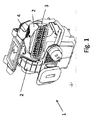
- the multi-part housing 2 has a fresh-air inlet opening 3 and a recirculating-air inlet opening 4 (FIG. Fig. 1 to 3 ).
- the fresh air inlet opening 3 has a substantially rectangular cross section, and the length of the fresh air inlet opening 3 is substantially greater than the height or the width of the fresh air inlet opening 3
- FIGS. 2 and 3 a part of the housing 2 is shown with a recirculating air flap 8 designed as a butterfly flap 9.
- the fresh air inlet opening 3 opens into the fresh air channel 5 and the recirculation inlet opening 4 opens into the recirculation channel 6. Both the fresh air channel 5 and the recirculating air channel 6 open into the feed air channel 7.
- the butterfly flap 9 about an axis of rotation 10th swiveling between a fresh air position and a recirculation position.
- the butterfly flap 9 is mounted as a recirculating air flap 8 by means of two bearing pins 17 on the housing 2 as a sliding bearing.
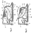
- Fig. 2 and 5 the recirculation position of the recirculating air flap 8 is shown.
- the fresh air duct 5 or the fresh air inlet opening 3 is closed by the recirculation damper 8 and the recirculation inlet opening 4 or the circulating air duct 6 is opened.
- Fig. 1 the butterfly flap 9 about an axis of rotation 10th swiveling between a fresh air position and a recirculation position.
- the butterfly flap 9 is mounted as a recirculating air flap 8 by means of two bearing pins 17 on the housing 2 as a sliding bearing.
- Fig. 2 and 5 the recirculation position of the recirculating air flap 8 is shown.
- the butterfly flap 9 has a first flap wing 11 and a second flap wing 12.
- the first flap wing 11 essentially clamps a first plane 13 (FIG. Fig. 4 ) and the second flap wing 12 biases a second plane 14.
- the first and second flap wings 11, 12 also also have a slight curvature.
- the first and second plane 13, 14 is thus not completely within the first and second flap wing 11, 12, but is only approximately inside the first and second flap wings 11, 12.
- the first plane 13 is placed in the first flap wing 11 in such a way that one end according to the section in FIG Fig.
- the extension of the first flap wing 11 in the direction of according to the first level in the section Fig. 4 is in Fig. 4 marked with a and the extension of the second flap wing 12 in the direction of the second plane 14 in the section perpendicular to the axis of rotation 10 according to Fig. 4 in Fig. 4 is marked with b.
- the ratio of a and b is greater than 1 and is in the range between 1.2 and 1.4.
- the extent a of the first flap wing 11 is thus greater than the extent b of the second flap wing 12.
- the butterfly flap 9 furthermore has a sealing edge 18 made of an elastic material and furthermore a first retaining wall 15 and a second retaining wall 16 are formed on the butterfly flap 9 (FIG. FIGS. 2 and 3 ). At the first and second retaining wall 15, 16 each have a bearing pin 17 is arranged, by means of which the butterfly flap 9 is mounted on the housing 2.
- the housing 2 and the butterfly valves 9 are made by injection molding of plastic.
- the circulating air flap 8 acts at a high driving speed of the motor vehicle with the motor vehicle air conditioning 1, a high back pressure on the butterfly valve 9.
- This high dynamic pressure acts both on the first flap wing 11 and on the second flap wing 12. Due to geometric alignment of the first and second flap wing 11, 12 to the rotation axis 10 and the two bearing pins 17 is to receive 17 of the two bearing pin 17 only a very small torque, because the slightly larger torque, which arises at the slightly larger first flap wing 11, is substantially canceled by the resulting torque at the second flap wing 12.
- a gear or a mechanism connected to an actuator only a very small torque can be absorbed.
- rattling of the butterfly flap 9 in the circulating air position can be avoided even with a high dynamic pressure acting on the recirculating air flap 8 and reliable sealing is ensured even at a high back pressure of the fresh air channel 5.
- the first and second flap wings 11, 12 has a curvature. This is in the fresh air position ( Fig. 3 and 4 ) a larger flow path of the fresh air from the fresh air inlet opening 3 to the supply air duct 7 possible.
- Fig. 2 and 5 illustrated circulating air position of the recirculating air flap 8 causes the curvature of the first and second flap wing 11, 12 a reduced flow cross-sectional area of the circulating air, which is passed through the recirculation inlet opening 4 to the supply air duct 7.
- the recirculating-air flap 8 designed as a butterfly flap 9 makes it possible to seal the fresh-air channel 5 reliably and without rattling even in the case of a high dynamic pressure acting on the recirculating-air flap 8 in a circulating-air position.
- the axis of rotation 10 of the butterfly blade 9 is substantially aligned, that is with a deviation of less than 30 °, 20 °, 10 ° or 5 °, parallel to the second axis of the fresh air channel 5.
- the first axis and the second axis are perpendicular to each other and the first axis indicates the direction of expansion of the fresh air duct 5 or the fresh air inlet opening 3 in a direction in which this expansion is greater than in the direction of the second axis.
- the first axis thus corresponds to the direction of the length in a substantially rectangular cross-sectional shape of the fresh air inlet opening 3 or the fresh air channel 5 and the second axis indicates the direction of the height or width.
Landscapes
- Physics & Mathematics (AREA)
- Thermal Sciences (AREA)
- Engineering & Computer Science (AREA)
- Mechanical Engineering (AREA)
- Air-Conditioning For Vehicles (AREA)
Abstract
Description
- Die Erfindung betrifft eine Kraftfahrzeugklimaanlage gemäß dem Oberbegriff des Anspruches 1.
- Kraftfahrzeugklimaanlagen dienen dazu, die dem Innenraum eines Kraftfahrzeuges zuzuführende Luft zu erwärmen und/oder zu kühlen. Die Kraftfahrzeugklimaanlagen sind mit verschiedenen als Luftklappen ausgebildeten Luftleiteinrichtungen versehen. Die Luftklappen dienen dabei z. B. zu steuern, ob dem Fahrzeuginnenraum Luft aus der Umgebung oder aus dem Fahrzeuginnenraum zugeführt wird. Diese Luftklappen werden als Umluftklappen bezeichnet. Ferner weist die Kraftfahrzeugklimaanlage außerdem zusätzliche Luftklappen auf welche dazu dienen, die in den Fahrzeuginnenraum leitbare Menge an Luft zu steuern. Zum Bewegen der Luftklappen werden als Aktuatoren beispielweise Stellantriebe mit einem Getriebe und einem Elektromotor verwendet.
- Als Umluftklappen werden sogenannten Fahnenklappen eingesetzt, welche an einer Rotationsachse nur einen Klappenflügel aufweisen. Beim Verschließen eines Frischluftkanals, in den eine Frischlufteinlassöffnung mündet, mit Hilfe der Fahnenklappe, wirkt auf diese Fahnenklappe bei einer hohen Fahrgeschwindigkeit eines Kraftfahrzeugs ein großer Staudruck. Da die Fahnenklappe nur einen Klappenflügel aufweist, entsteht damit an der Rotationsachse ein großes Drehmoment, der von einem Getriebe oder einem Stellantrieb aufgenommen werden muss. Deshalb kommt es zu Klapperoder Pfeifgeräuschen und es ist eine nur eine unzureichende Abdichtung bei einem derart hohen Staudruck mit Hilfe dieser Fahnenklappe möglich.
- Aus der
EP 1 095 802 A1 ist eine Umluftklappe bekannt, welche als Trommelklappe ausgebildet ist. Die Trommelklappe benötigt jedoch in nachteiliger Weise einen großen Bauraum und ist für die Abdichtung von Frischluftkanälen mit einer wesentlich größeren Länge als Breite nur bedingt geeignet. - Die Aufgabe der vorliegenden Erfindung besteht deshalb darin, eine Kraftfahrzeugklimaanlage mit einer Umluftklappe zur Verfügung zu stellen, bei der mit der Umluftklappe auch bei einem großen Staudruck ein im Querschnitt rechteckförmiger Frischluftkanal zuverlässig abgedichtet werden kann.
- Diese Aufgabe wird gelöst mit einer Kraftfahrzeugklimaanlage, umfassend ein Gehäuse, einen Frischluftkanal zum Durchleiten von Frischluft aus einer Umgebung eines Kraftfahrzeuges, einen Umluftluftkanal zum Durchleiten von Umluft aus einem Innenraum des Kraftfahrzeuges, einen Zuführungsluftkanal zum Durchleiten von Frischluft und/oder von Umluft, wenigstens eine verschwenkbare Umluftklappe, welche in einer Frischluftstellung den Umluftkanal verschließt und der Frischluftkanal geöffnet ist und in einer Umluftstellung den Frischluftkanal verschließt und der Umluftkanal geöffnet ist, wobei die Umluftklappe als eine Schmetterlingsklappe ausgebildet ist.
- In einer ergänzenden Ausführungsform weist die Kraftfahrzeugklimaanlage nur eine Umluftklappe auf.
- In einer zusätzlichen Variante ist die Schmetterlingsklappe um eine Rotationsachse verschwenkbar gelagert und/oder die Schmetterlingsklappe weist einen ersten Klappenflügel und einen zweiten Klappenflügel auf, vorzugsweise ist der erste und zweite Klappenflügel gegenüberliegend an der Rotationsachse ausgebildet. Die Schmetterlingsklappe weist den ersten und zweiten Klappenflügel auf und mit dem ersten und zweiten Klappenflügel sind in der Umluftstellung der Schmetterlingsklappe der Frischluftkanal verschlossen, sodass ein auf die Schmetterlingsklappe wirkender hoher Staudruck in dem Frischluftkanal sowohl auf den ersten Klappenflügel als auch auf den zweiten Klappenflügel aufwirkt und dadurch das an der Rotationsachse wirkende Drehmoment wenigstens teilweise aufgehoben ist, weil das auf den ersten Klappenflügel wirkende Drehmoment das auf den zweiten Klappenflügel wirkenden Drehmoment oder dem am zweiten Klappenflügel entstehenden oder wirkenden Drehmoment entgegengesetzt gerichtet ist. Auch in der Frischluftstellung der Schmetterlingsklappe ist von dem ersten und zweiten Klappenflügel der Umluftkanal verschlossen.
- In einer weiteren Ausführungsform sind eine von dem ersten Klappenflügel aufgespannte erste Ebene und eine von dem zweiten Klappenflügel aufgespannte zweite Ebene im Wesentlichen parallel zueinander ausgerichtet und vorzugsweise ist der Abstand der ersten Ebene von der zweiten Ebene senkrecht zu der ersten und/oder zweiten Ebene an der Schmetterlingsklappe kleiner als 3 cm oder 2 cm oder ist Null. Im Wesentlichen parallel zueinander gerichtet bedeutet vorzugsweise, dass die erste Ebene und die zweite Ebene in einem Winkel von weniger als 30°, 20°, 10° oder 5° zueinander ausgerichtet sind, insbesondere in einem Schnitt senkrecht zu der Rotationsachse.
- Zweckmäßig liegt das Verhältnis der Ausdehnung des ersten Klappenflügels in Richtung der ersten Ebene zu der Ausdehnung des zweiten Klappenflügels in Richtung der zweiten Ebene, jeweils in einem Schnitt senkrecht zu der Rotationsachse, zwischen 1 und 1,8, vorzugsweise zwischen 1 und 1,5.
- In einer ergänzenden Ausgestaltung sind der ersten Klappenflügel und/oder der zweite Klappenflügel gekrümmt ausgebildet.
- In einer zusätzlichen Ausführungsform sind der erste Klappenflügel und/oder der zweite Klappenflügel in einem Schnitt senkrecht zu der Rotationsachse gekrümmt ausgebildet.
- In einer zusätzlichen Variante sind der ersten Klappenflügel und/oder der zweite Klappenflügel in einem Abstand zu der Rotationsachse ausgerichtet. Zweckmäßig liegt der Abstand zwischen 0,1 und 4 cm, insbesondere zwischen 0,5 und 3 cm. In einer zusätzlichen Ausgestaltung sind die erste Ebene und/oder die zweite Ebene in dem Abstand zu der Rotationsachse ausgerichtet.
- In einer zusätzlichen Ausführungsform ist an dem ersten Klappenflügel und/oder an dem zweiten Klappenflügel eine erste und zweite Haltewandung ausgebildet und vorzugsweise ist die erste und zweite Haltewandung im Wesentlichen senkrecht zu der Rotationsachse ausgerichtet.
- Vorzugsweise ist die Ausdehnung des Frischluftkanals senkrecht zu der Strömungsrichtung der Frischluft in dem Frischluftkanal in Richtung einer ersten Achse größer als in Richtung einer zweiten Achse und die erste und zweite Achse stehen senkrecht aufeinander. Dabei liegen vorzugsweise die erste und zweite Achse in einer Ebene, wobei die Ebene insbesondere senkrecht zu der Strömungsrichtung der Frischluft in dem Frischluftkanal und/oder einer Längsachse des Frischluftkanales ausgerichtet ist.
- In einer ergänzenden Variante ist die Ausdehnung des Frischluftkanales in Richtung der ersten Achse wenigstens um das 2-, 3-, 5-, 7- oder 10-Fache größer als in Richtung der zweiten Achse und/oder der Frischluftkanal weist einen im Wesentlichen rechteckförmigen Querschnitt auf.
- In einer zusätzlichen Ausgestaltung ist die erste Achse und die zweite Achse senkrecht zu der Strömungsrichtung der Frischluft ausgerichtet.
- In einer weiteren Ausführungsform weist die Umluftklappe einen Dichtrand, z. B. einen Rand aus einem elastischen Material oder eine Schaumdichtung, auf. Der Dichtrand dient dazu, dass beim Anliegen der Umluftklappe an dem Gehäuse oder einer Wandung des Gehäuses eine im Wesentlichen vollständige Abdichtung mit Hilfe der Umluftklappe möglich ist.
- In einer ergänzenden Ausführungsform ist die wenigstens eine Umluftklappe mittels einer Gleitlagerung mit dem Gehäuse verbunden.
- In einer zusätzlichen Ausgestaltung umfasst die Kraftfahrzeugklimaanlage einen Aktuator, z. B. einen Elektromotor, und einen Mechanismus oder ein Getriebe und der Aktuator ist mit der Umluftklappe mechanischen (mittels des Mechanismus oder des Getriebes) verbunden, so dass die wenigstens eine Umluftklappe mittels des Mechanismus oder Getriebes von dem Aktuator bewegbar ist.
- In einer weiteren Variante umfasst die Kraftfahrzeugklimaanlage ein Gebläse und/oder einen Kältemittelverdampfer und/oder eine Heizeinrichtung und/oder der Zuführungskanal mündet zu dem Gebläse und/oder den Kältemittelverdampfer und/oder die Heizeinrichtung.
- In einer weiteren Ausführungsform weist der Kunststoff des Dichtrandes größere elastische Eigenschaften auf als der Kunststoff der wenigstens einen Luftklappe außerhalb des Dichtrandes, beispielsweise besteht der Dichtrand aus einem weichen Kunststoff und die übrige Luftklappe aus einem harten Kunststoff.
- In einer Variante sind das Gehäuse und die wenigstens eine Luftklappe einstückig mit Spritzgießen, insbesondere aus Kunststoff, hergestellt.
- In einer ergänzenden Ausgestaltung ist das Gehäuse und/oder die wenigstens eine Luftklappe aus thermoplastischen und/oder duroplastischen und/oder elastomeren Kunststoff hergestellt oder wird aus diesem hergestellt.
- Zweckmäßig ist das Gehäuse der Kraftfahrzeugklimaanlage ein- oder mehrteilig.
- In einer weiteren Ausgestaltung weist die Kraftfahrzeugklimaanlage wenigstens eine Luftklappe oder ein Rollo auf, um die Menge der durch einen Luftkanal leitbaren Menge an Luft zu steuern.
- In einer zusätzlichen Ausgestaltung besteht das Gehäuse der Kraftfahrzeug- klimaanlage aus dem gleichen oder einem anderen Kunststoff als die wenigstens eine Luftklappe.
- In einer weiteren Ausgestaltung ist der Aktuator ein Elektromotor oder ein Piezoelement.
- Vorzugsweise weist die Kraftfahrzeugklimaanlage wenigstens einen Luftkanal zum Durchleiten von Luft auf.
- Insbesondere besteht das Gehäuse der Kraftfahrzeugklimaanlage wenigstens teilweise aus Kunststoff.
- Zweckmäßig sind der Frischluftkanal und/oder der Umluftkanal und/oder der Zuführungskanal von einer Wandung des Gehäuses begrenzt.
- In einer weiteren Ausgestaltung weist der Aktuator eine Positionsermittlungseinrichtung zur Erfassung der Lage des Mechanismus, z. B. einer Welle, auf.
- Insbesondere ist die Positionsermittlungseinheit mit einer Steuerungseinheit für die Kraftfahrzeugklimaanlage verbunden und mittels der von der Positionsermittlungseinheit erfassten Daten der Aktuator steuerbar zur Erzielung einer bestimmten Lage des Mechanismus bzw. der wenigstens einen Luftklappe.
- Im Nachfolgenden werden Ausführungsbeispiele der Erfindung unter Bezugnahme auf die beigefügten Zeichnungen näher beschrieben. Es zeigt:
- Fig. 1
- eine perspektivische Ansicht einer Kraftfahrzeugklimaanlage,
- Fig. 2
- eine perspektivische Ansicht eines Teils eines Gehäuses der Kraftfahrzeugklimaanlage gemäß
Fig. 1 mit einer Umluftklappe in einer Umluftstellung, - Fig. 3
- eine perspektivische Ansicht des Teils des Gehäuses der Kraftfahrzeugklimaanlage gemäß
Fig 1 mit der Umluftklappe in einer Frischluftstellung, - Fig. 4
- einen Schnitt des Teils des Gehäuses gemäß
Fig. 3 senkrecht zu einer Rotationsachse der Umluftklappe und - Fig 5
- einen Schnitt des Teils des Gehäuses gemäß
Fig. 2 senkrecht zu einer Rotationsachse der Umluftklappe. - Kraftfahrzeugklimaanlagen 1 dienen dazu, die einem Fahrzeuginnenraum eines Kraftfahrzeuges zuzuführende Luft zu kühlen und/oder zu erwärmen. Hierzu weist die Kraftfahrzeugklimaanlage 1 ein Gehäuse 2 aus im Allgemeinen thermoplastischem Kunststoff auf. Das Gehäuse 2 ist mit Wandungen ausgebildet, welche auch einen Luftkanal, beispielsweise als Frischluftkanal 5, Umluftkanal 6 und/oder Zuführungsluftkanal 7, begrenzen. Durch den Luftkanal wird zu kühlende und/oder zu erwärmende Luft geleitet. Innerhalb des Luftkanales als Zuführungsluftkanal 7 sind außerdem ein nicht dargestellter Kältemittelverdampfer und eine nicht dargestellte Heizeinrichtung, beispielsweise eine elektrische Heizeinrichtung und/oder ein Wärmeübertrager, durch welchen Kühlmittel eines Verbrennungsmotors geleitet wird zur Übertragung von Wärme von dem Kühlmittel auf die durch den Luftkanal geleitete Luft. Das Gehäuse 1 dient ebenfalls zur Aufnahme eines Gebläses (nicht dargestellt).
- Das mehrteilige Gehäuse 2 weist eine Frischlutteinlassöffnung 3 und eine Umlufteinlassöffnung 4 auf (
Fig. 1 bis 3 ). Die Frischlufteinlassöffnung 3 weist einen im Wesentlichen rechteckförmigen Querschnitt auf und dabei ist die Länge der Frischlufteinlassöffnung 3 wesentlich größer als die Höhe bzw. die Breite der Frischlufteinlassöffnung 3. InFig. 2 und 3 ist ein Teil des Gehäuses 2 mit einer als Schmetterlingsklappe 9 ausgebildeten Umluftklappe 8 abgebildet. Die Frischlufteinlassöffnung 3 mündet in den Frischluftkanal 5 und die Umlufteinlassöffnung 4 mündet in den Umluftkanal 6. Sowohl der Frischluftkanal 5 als auch der Umluftkanal 6 münden in den Zuführungsluftkanal 7. Innerhalb des Gehäuses 2 der Kraftfahrzeug-Klimaanlage 1 ist die Schmetterlingsklappe 9 um eine Rotationsachse 10 verschwenkbar zwischen einer Frischluftstellung und einer Umluftstellung. Hierzu ist die Schmetterlingsklappe 9 als Umluftklappe 8 mittels zweier Lagerbolzen 17 an dem Gehäuse 2 als Gleitlagerung gelagert. InFig. 2 und5 ist die Umluftstellung der Umluftklappe 8 dargestellt. In der Umluftstellung der Umluftklappe 8 ist von der Umluftklappe 8 der Frischluftkanal 5 bzw. die Frischlufteinlassöffnung 3 verschlossen und die Umlufteinlassöffnung 4 bzw. der Umluftkanal 6 geöffnet. In dieser, inFig. 2 und5 dargestellten Umluftstellung der Umluftklappe 8 kann die Luft durch die Umlufteinlassöffnung 4 in den Zuführungskanal 7 strömen und durch die Frischlufteinlassöffnung 8 keine Luft in den Zuführungsluftkanal geleitet werden. Damit wird in den Fahrzeuginnenraum des Kraftfahrzeugs ausschließlich Umluft, das heißt Luft aus dem Fahrzeuginnenraum eingeleitet. - In der in
Fig. 3 und4 dargestellten Frischluftstellung der Umluftklappe 8 ist von der Umluftklappe 8 die Umlufteinlassöffnung 4 bzw. der Umluftkanal 6 verschlossen und die Frischlufteinlassöffnung 3 bzw. der Frischluftkanal 5 geöffnet. Dadurch kann in der Frischluftstellung der Umluftklappe 8 die Frischluft aus der Umgebung des Kraftfahrzeuges in den Zuführungskanal 7 eingeleitet werden, welche anschließend von einem Gebläse gefördert und optional an einem Kältemittelverdampfer gekühlt und/oder der Heizeinrichtung erwärmt wird vor dem Einleiten in den Fahrzeuginnenraum des Kraftfahrzeuges. - Die Schmetterlingsklappe 9 weist einen ersten Klappenflügel 11 und einen zweiten Klappenflügel 12 auf. Der erste Klappenflügel 11 spannt dabei im Wesentlichen eine erste Ebene 13 (
Fig. 4 ) auf und der zweite Klappenflügel 12 spannt eine zweite Ebene 14 auf. In dem Schnitt gemäßFig. 4 und 5 senkrecht zu der Rotationsachse 10 der Schmetterlingsklappe 9 weist der erste und zweite Klappenflügel 11, 12 ferner auch eine leichte Krümmung auf. Die erste und zweite Ebene 13, 14 liegt somit nicht vollständig innerhalb des ersten und zweiten Klappenflügels 11, 12, sondern befindet sich nur annähernd innerhalb des ersten und zweiten Klappenflügels 11, 12. Vorzugsweise ist dabei die erste Ebene 13 dahingehend in den ersten Klappenflügel 11 gelegt, dass ein Ende gemäß dem Schnitt inFig. 4 des ersten Klappenflügels 11 an dem Gehäuse 2 und das Ende des ersten Klappenflügels 11 zum Beginn des zweiten Klappenflügels 12 die erste Ebene 13 schneidet und dies gilt ebenfalls für die zweite Ebene 14 an dem zweiten Klappenflügel 12. Die Ausdehnung des ersten Klappenflügels 11 in Richtung der ersten Ebene in dem Schnitt gemäßFig. 4 ist inFig. 4 mit a gekennzeichnet und die Ausdehnung des zweiten Klappenflügels 12 in Richtung der zweiten Ebene 14 in dem Schnitt senkrecht zur Rotationsachse 10 gemäßFig. 4 inFig. 4 ist mit b gekennzeichnet. Dabei ist das Verhältnis aus a und b größer als 1 und liegt im Bereich zwischen 1,2 und 1,4. Die Ausdehnung a des ersten Klappenflügels 11 ist damit größer als die Ausdehnung b des zweiten Klappenflügels 12. - Die Schmetterlingsklappe 9 weist ferner einen Dichtrand 18 aus einem elastischen Material auf und ferner sind an der Schmetterlingsklappe 9 eine erste Haltewandung 15 und eine zweite Haltewandung 16 ausgebildet (
Fig. 2 und 3 ). An der ersten und zweiten Haltewandung 15, 16 ist jeweils ein Lagerbolzen 17 angeordnet, mittels dem die Schmetterlingsklappe 9 an dem Gehäuse 2 gelagert ist. Das Gehäuse 2 als auch die Schmetterlingsklappen 9 sind dabei mittels Spritzgießen aus Kunststoff hergestellt. - In der in
Fig. 2 und5 dargestellten Umluftstellung der Schmetterlingsklappe 9 bzw. der Umluftklappe 8 wirkt bei einer hohen Fahrgeschwindigkeit des Kraftfahrzeuges mit der Kraftfahrzeugklimaanlage 1 ein hoher Staudruck an der Schmetterlingsklappe 9. Dieser hohe Staudruck wirkt dabei sowohl auf den ersten Klappenflügel 11 als auch auf den zweiten Klappenflügel 12. Aufgrund der geometrischen Ausrichtung des ersten und zweiten Klappenflügels 11, 12 zu der Rotationsachse 10 bzw. den beiden Lagerbolzen 17 ist von den beiden Lagerbolzen 17 nur ein sehr geringes Drehmoment aufzunehmen, weil das geringfügig größere Drehmoment, welches an dem geringfügig größeren ersten Klappenflügel 11 entsteht, im Wesentlichen von dem an dem zweiten Klappenflügel 12 entstehende Drehmoment aufgehoben ist. Dadurch braucht auch bei hohen Fahrgeschwindigkeiten in der Umluftstellung gemäßFig. 2 und4 , von einem Getriebe oder einem Mechanismus, der mit einem Aktuator verbunden ist, nur ein sehr geringes Drehmoment aufgenommen werden. Dadurch kann ein Klappern der Schmetterlingsklappe 9 in der Umluftstellung auch bei einem hohen, auf die Umluftklappe 8 wirkenden Staudruck vermieden werden und es ist ein zuverlässiges Abdichten auch bei einem hohen Staudruck des Frischluftkanals 5 gewährleistet. - Der erste und zweite Klappenflügel 11, 12 weist eine Krümmung auf. Dadurch ist in der Frischluftstellung (
Fig. 3 und4 ) ein größerer Strömungsweg der Frischluft von der Frischlufteinlassöffnung 3 zu dem Zuführungsluftkanal 7 möglich. In der inFig. 2 und5 dargestellten Umluftstellung der Umluftklappe 8 bedingt die Krümmung des ersten und zweiten Klappenflügels 11, 12 eine verkleinerte Strömungsquerschnittsfläche der Umluft, welche durch die Umlufteinlassöffnung 4 zu dem Zuführungsluftkanal 7 geleitet ist. Beim Ansaugen von Umluft aus dem Fahrzeuginnenraum in der Umluftstellung der Schmetterlingsklappe 9 treten insgesamt aufgrund des kürzeren Strömungsweges geringere Strömungswiderstände auf, sodass die verkleinerte Strömungsquerschnittsfläche der Umluft in der Umluftstellung der Schmetterlingsklappe 9 gewünscht ist. Bei einem Stillstand des Kraftfahrzeugs und einem Ansaugen von Frischluft mittels des Gebläses durch die Frischlufteinlassöffnung 3 treten größere Strömungswege und damit Widerstände der Luft auf, sodass in der inFig. 3 und4 dargestellten Frischluftstellung der Umluftklappe 8 eine größere Strömungsquerschnittsfläche erwünscht und auch möglich ist, aufgrund der Krümmung des ersten und zweiten Klappenflügels 11, 12. - Insgesamt betrachtet sind mit der erfindungsgemäßen Kraftfahrzeugklimaanlage 1 wesentliche Vorteile verbunden. Die als Schmetterlingsklappe 9 ausgebildete Umluftklappe 8 ermöglicht es, auch bei einem hohen, auf die Umluftklappe 8 wirkenden Staudruck in einer Umluftstellung, den Frischluftkanal 5 zuverlässig und ohne Klappern abzudichten. Die Rotationsachse 10 der Schmetterlingskfappe 9 ist dabei im Wesentlichen, das heißt mit einer Abweichung von weniger als 30°, 20°, 10° oder 5°, parallel zu der zweiten Achse an dem Frischluftkanal 5 ausgerichtet. Die erste Achse und die zweite Achse stehen dabei aufeinander senkrecht und die erste Achse gibt die Richtung der Ausdehnung des Frischluftkanals 5 oder der Frischlufteinlassöffnung 3 in einer Richtung an, in der diese Ausdehnung größer ist als in Richtung der zweiten Achse. Die erste Achse entspricht somit bei einer im Wesentlichen rechteckförmigen Querschnittsform der Frischlufteinlassöffnung 3 oder des Frischluftkanals 5 der Richtung der Länge und die zweite Achse gibt die Richtung der Höhe oder Breite an.
-
- 1
- Kraftfahrzeugklimaanlage
- 2
- Gehäuse
- 3
- Frischlufteinlassöffnung
- 4
- Umlufteinlassöffnung
- 5
- Frischluftkanal
- 6
- Umluftkanal
- 7
- Zuführungsluftkanal
- 8
- Umluftklappe
- 9
- Schmetterlingsklappe
- 10
- Rotationsachse
- 11
- Erster Klappenflügel
- 12
- Zweiter Klappenflügel
- 13
- Erste Ebene
- 14
- Zweite Ebene
- 15
- Erste Haltewandung
- 16
- Zweite Haltewandung
- 17
- Lagerbolzen
- 18
- Dichtrand
Claims (15)
- Kraftfahrzeugklimaanlage (1), umfassend- ein Gehäuse (2),- einen Frischluftkanal (5) zum Durchleiten von Frischluft aus einer Umgebung eines Kraftfahrzeuges,- einen Umluftluftkanal (6) zum Durchleiten von Umluft aus einem Innenraum des Kraftfahrzeuges,- einen Zuführungsluftkanal (7) zum Durchleiten von Frischluft und/oder von Umluft,- wenigstens eine verschwenkbare Umluftklappe (8), welche in einer Frischluftstellung den Umluftkanal (6) verschließt und der Frischluftkanal (5) geöffnet ist und in einer Umluftstellung den Frischluftkanal (5) verschließt und der Umluftkanal (6) geöffnet ist,dadurch gekennzeichnet, dass
die Umluftklappe (8) als eine Schmetterlingsklappe (9) ausgebildet ist. - Kraftfahrzeugklimaanlage nach Anspruch 1,
dadurch gekennzeichnet, dass
die Kraftfahrzeugklimaanlage (1) nur eine Umluftklappe (8) aufweist. - Kraftfahrzeugklimaanlage nach Anspruch 1 oder 2,
dadurch gekennzeichnet, dass
die Schmetterlingsklappe (9) um eine Rotationsachse (10) verschwenkbar gelagert ist
und/oder
die Schmetterlingsklappe (9) einen ersten Klappenflügel (11) und einen zweiten Klappenflügel (12) aufweist. - Kraftfahrzeugklimaanlage nach Anspruch 3,
dadurch gekennzeichnet, dass
eine von dem ersten Klappenflügel (11) aufgespannte erste Ebene (13) und eine von dem zweiten Klappenflügel (12) aufgespannte zweite Ebene (14) im Wesentlichen parallel zueinander ausgerichtet sind und vorzugsweise der Abstand der ersten Ebene (13) von der zweiten Ebene (14) senkrecht zu der ersten und/oder zweiten Ebene (13, 14) an der Schmetterlingsklappe (9) kleiner als 3 cm oder 2 cm ist oder Null ist. - Kraftfahrzeugklimaanlage nach Anspruch 3 oder 4,
dadurch gekennzeichnet, dass
das Verhältnis der Ausdehnung des ersten Klappenflügels (11) in Richtung der ersten Ebene (13) zu der Ausdehnung des zweiten Klappenflügels (12) in Richtung der zweiten Ebene (14), jeweils in einem Schnitt senkrecht zu der Rotationsachse (10), zwischen 1 und 1,8, vorzugsweise zwischen 1 und 1,5, liegt. - Kraftfahrzeugklimaanlage nach einem oder mehreren der Ansprüche 3 bis 5,
dadurch gekennzeichnet, dass
der ersten Klappenflügel (11) und/oder der zweite Klappenflügel (12) gekrümmt ausgebildet sind. - Kraftfahrzeugklimaanlage nach Anspruch 6,
dadurch gekennzeichnet, dass
der erste Klappenflügel (11) und/oder der zweite Klappenflügel (12) in einem Schnitt senkrecht zu der Rotationsachse (10) gekrümmt ausgebildet sind. - Kraftfahrzeugklimaanlage nach einem oder mehreren der Ansprüche 3 bis 7,
dadurch gekennzeichnet, dass
der ersten Klappenflügel (11) und/oder der zweite Klappenflügel (12) in einem Abstand zu der Rotationsachse (10) ausgerichtet sind. - Kraftfahrzeugklimaanlage nach einem oder mehreren der Ansprüche 3 bis 8,
dadurch gekennzeichnet, dass
an dem ersten Klappenflügel (11) und/oder an dem zweiten Klappenflügel (12) eine erste und zweite Haltewandung (15, 16) ausgebildet ist und vorzugsweise die erste und zweite Haltewandung (15, 16) im Wesentlichen senkrecht zu der Rotationsachse (10) ausgerichtet ist. - Kraftfahrzeugklimaanlage nach einem oder mehreren der vorhergehenden Ansprüche,
dadurch gekennzeichnet, dass
die Ausdehnung des Frischluftkanales (5) senkrecht zu der Strömungsrichtung der Frischluft in dem Frischluftkanal (5) in Richtung einer ersten Achse größer ist als in Richtung einer zweiten Achse und die erste und zweite Achse senkrecht aufeinander stehen. - Kraftfahrzeugklimaanlage nach Anspruch 11,
dadurch gekennzeichnet, dass
die Ausdehnung des Frischluftkanales (5) in Richtung der ersten Achse wenigstens um das 2-, 3-, 5-, 7- oder 10-Fache größer ist als in Richtung der zweiten Achse
und/oder
der Frischluftkanal (5) einen im Wesentlichen rechteckförmigen Querschnitt aufweist. - Kraftfahrzeugklimaanlage nach einem oder mehreren der vorhergehenden Ansprüche,
dadurch gekennzeichnet, dass
die Umluftklappe (8) einen Dichtrand (18), z. B. einen Rand aus einem elastischen Material oder eine Schaumdichtung, aufweist. - Kraftfahrzeugklimaanlage nach einem oder mehreren der vorhergehenden Ansprüche,
dadurch gekennzeichnet, dass
die wenigstens eine Umluftklappe (8) mittels einer Gleitlagerung mit dem Gehäuse (2) verbunden ist. - Kraftfahrzeugklimaanlage nach einem oder mehreren der vorhergehenden Ansprüche,
dadurch gekennzeichnet, dass
die Kraftfahrzeugklimaanlage (1) einen Aktuator, wie einen Elektromotor oder einen mechanischen Bedienschalter, und einen Mechanismus, wie ein Getriebe oder einen Bowdenzug, umfasst und der Aktuator mit der Umluftklappe (8) mechanisch verbunden ist, so dass die wenigstens eine Umluftklappe (8) mittels des Mechanismus von dem Aktuator bewegbar ist. - Kraftfahrzeugklimaanlage nach einem oder mehreren der vorhergehenden Ansprüche,
dadurch gekennzeichnet, dass
die Kraftfahrzeugklimaanlage (1) ein Gebläse und/oder einen Kältemittelverdampfer und/oder eine Heizeinrichtung umfasst und/oder
der Zuführungskanal (7) zu dem Gebläse und/oder den Kältemittelverdampfer und/oder die Heizeinrichtung mündet.
Priority Applications (1)
| Application Number | Priority Date | Filing Date | Title |
|---|---|---|---|
| EP10290350.7A EP2402183B1 (de) | 2010-06-29 | 2010-06-29 | Kraftfahrzeugklimaanlage |
Applications Claiming Priority (1)
| Application Number | Priority Date | Filing Date | Title |
|---|---|---|---|
| EP10290350.7A EP2402183B1 (de) | 2010-06-29 | 2010-06-29 | Kraftfahrzeugklimaanlage |
Publications (2)
| Publication Number | Publication Date |
|---|---|
| EP2402183A1 true EP2402183A1 (de) | 2012-01-04 |
| EP2402183B1 EP2402183B1 (de) | 2017-09-06 |
Family
ID=42983550
Family Applications (1)
| Application Number | Title | Priority Date | Filing Date |
|---|---|---|---|
| EP10290350.7A Not-in-force EP2402183B1 (de) | 2010-06-29 | 2010-06-29 | Kraftfahrzeugklimaanlage |
Country Status (1)
| Country | Link |
|---|---|
| EP (1) | EP2402183B1 (de) |
Cited By (3)
| Publication number | Priority date | Publication date | Assignee | Title |
|---|---|---|---|---|
| US20150147950A1 (en) * | 2013-11-28 | 2015-05-28 | MAHLE Behr France Rouffach SAS | Air-conditioning system for a vehicle |
| WO2015144418A1 (fr) * | 2014-03-28 | 2015-10-01 | Valeo Systemes Thermiques | Boîtier d'admission d'air pour installation de ventilation de véhicule automobile |
| DE102018206986A1 (de) * | 2018-05-04 | 2019-11-07 | Mahle International Gmbh | Frischluft-Umluft-Klappenanordnung |
Citations (5)
| Publication number | Priority date | Publication date | Assignee | Title |
|---|---|---|---|---|
| DE19915966A1 (de) * | 1998-04-21 | 1999-10-28 | Valeo Climatisation | Lufteinlaßgehäuse für eine Heizungs- und/oder Klimaanlage für Kraftfahrzeuge |
| EP1095802A1 (de) | 1999-10-27 | 2001-05-02 | Valeo Climatisation | Luftsteueranordnung für eine Ventilation, Heizung und/oder Klimaanlage eines Kraftfahrzeugs |
| US20010012756A1 (en) * | 1999-12-07 | 2001-08-09 | Michael Komowski | Air flap for a ventilation, heating or air conditioning system of a motor vehicle |
| EP1308325A2 (de) * | 2001-11-02 | 2003-05-07 | Behr GmbH & Co. | Luftstromschalteinrichtung |
| EP1759897A1 (de) * | 2005-09-01 | 2007-03-07 | Behr GmbH & Co. KG | Luftstromschalteinrichtung |
Family Cites Families (1)
| Publication number | Priority date | Publication date | Assignee | Title |
|---|---|---|---|---|
| JP5500805B2 (ja) * | 2008-09-02 | 2014-05-21 | 株式会社ヴァレオジャパン | 車両用空調装置 |
-
2010
- 2010-06-29 EP EP10290350.7A patent/EP2402183B1/de not_active Not-in-force
Patent Citations (5)
| Publication number | Priority date | Publication date | Assignee | Title |
|---|---|---|---|---|
| DE19915966A1 (de) * | 1998-04-21 | 1999-10-28 | Valeo Climatisation | Lufteinlaßgehäuse für eine Heizungs- und/oder Klimaanlage für Kraftfahrzeuge |
| EP1095802A1 (de) | 1999-10-27 | 2001-05-02 | Valeo Climatisation | Luftsteueranordnung für eine Ventilation, Heizung und/oder Klimaanlage eines Kraftfahrzeugs |
| US20010012756A1 (en) * | 1999-12-07 | 2001-08-09 | Michael Komowski | Air flap for a ventilation, heating or air conditioning system of a motor vehicle |
| EP1308325A2 (de) * | 2001-11-02 | 2003-05-07 | Behr GmbH & Co. | Luftstromschalteinrichtung |
| EP1759897A1 (de) * | 2005-09-01 | 2007-03-07 | Behr GmbH & Co. KG | Luftstromschalteinrichtung |
Cited By (8)
| Publication number | Priority date | Publication date | Assignee | Title |
|---|---|---|---|---|
| US20150147950A1 (en) * | 2013-11-28 | 2015-05-28 | MAHLE Behr France Rouffach SAS | Air-conditioning system for a vehicle |
| CN104669983A (zh) * | 2013-11-28 | 2015-06-03 | 马勒贝洱法国鲁法克股份有限公司 | 车辆空调系统 |
| EP2878466A1 (de) * | 2013-11-28 | 2015-06-03 | Mahle Behr France Rouffach S.A.S | Klimatisierungsanlage für ein Fahrzeug |
| US10155429B2 (en) * | 2013-11-28 | 2018-12-18 | MAHLE Behr France Rouffach SAS | Air-conditioning system for a vehicle |
| WO2015144418A1 (fr) * | 2014-03-28 | 2015-10-01 | Valeo Systemes Thermiques | Boîtier d'admission d'air pour installation de ventilation de véhicule automobile |
| FR3019101A1 (fr) * | 2014-03-28 | 2015-10-02 | Valeo Systemes Thermiques | Boitier d'admission d'air pour installation de ventilation de vehicule automobile |
| CN106163841A (zh) * | 2014-03-28 | 2016-11-23 | 法雷奥热系统公司 | 用于机动车辆通风设施的进气壳体 |
| DE102018206986A1 (de) * | 2018-05-04 | 2019-11-07 | Mahle International Gmbh | Frischluft-Umluft-Klappenanordnung |
Also Published As
| Publication number | Publication date |
|---|---|
| EP2402183B1 (de) | 2017-09-06 |
Similar Documents
| Publication | Publication Date | Title |
|---|---|---|
| DE69611592T2 (de) | Luftkanal-Schaltvorrichtung und Fahrzeug-Klimaanlage unter Verwendung derselben | |
| EP1902876B1 (de) | Luftführungsgehäuse, insbesondere für eine Kraftfahrzeug-Klimaanlage, mit einer Verteilerklappe und Verfahren zur Regelung einer derartigen Verteilerklappe | |
| EP1719645B2 (de) | Stellvorrichtung für wenigstens drei Klappen einer Belüftungs-, Heizungs-oder Klimaanlage eines Kraftfahrzeugs | |
| EP1930191B1 (de) | Fahrzeugheizungs- und/oder Klimaanlage mit kombinierter Luftmisch- und -verteilerklappe | |
| EP1682367B1 (de) | Trommelklappe | |
| EP2402183B1 (de) | Kraftfahrzeugklimaanlage | |
| DE102006009735A1 (de) | Äusseres Wärmeaustauschersystem für eine Fahrzeugklimaanlage | |
| DE202010016053U1 (de) | Kraftfahrzeugklimaanlage | |
| DE102014105115A1 (de) | Luftleiteinrichtung eines Klimatisierungssystems für ein Kraftfahrzeug | |
| EP2433825A1 (de) | Kraftfahrzeugklimaanlage | |
| EP3530505A1 (de) | Luftausströmer | |
| DE102015109354A1 (de) | Anordnung zur Luftverteilung für ein Klimatisierungssystem eines Kraftfahrzeugs | |
| DE102016116925B4 (de) | Fahrzeug-Beheizungs-, -Belüftungs- und Luftkühlungs-System | |
| DE10147112A1 (de) | Steuerklappe, z.B. für eine Vorrichtung zum Temperieren und Belüften von Kraftfahrzeugen | |
| DE10256619B3 (de) | Klimagerät für Fahrzeuge | |
| DE102011077639A1 (de) | Kraftfahrzeugklimaanlage | |
| DE102019205929A1 (de) | Kraftfahrzeugklimaanlage | |
| DE102015107658A1 (de) | Anordnung zur Luftverteilung für ein Klimatisierungssystem eines Kraftfahrzeuges | |
| EP1930193B1 (de) | Vorrichtung zur Luftmengenregelung, insbesondere für eine Kraftfahrzeug-Klimaanlage | |
| DE102007049340A1 (de) | Kraftfahrzeug-Klimaanlagenanordnung | |
| EP1843908B1 (de) | Kraftfahrzeug-klimaanlage | |
| EP1407903B1 (de) | Heizungs- oder Klimaanlage für ein Kraftfahrzeug mit einer Vorrichtung zur Regelung der Luftzufuhr | |
| DE102021117183A1 (de) | Lufteinlassvorrichtung sowie Heizungs-, Lüftungs- und/oder Klimatisierungsvorrichtung mit Lufteinlassvorrichtung | |
| DE102017108944A1 (de) | Heizungs-, Lüftungs- und/oder Klimatisierungsvorrichtung und Kraftfahrzeug | |
| DE102019131470A1 (de) | Heizungs-, Lüftungs- und/oder Klimaanlage für ein Kraftfahrzeug |
Legal Events
| Date | Code | Title | Description |
|---|---|---|---|
| AK | Designated contracting states |
Kind code of ref document: A1 Designated state(s): AL AT BE BG CH CY CZ DE DK EE ES FI FR GB GR HR HU IE IS IT LI LT LU LV MC MK MT NL NO PL PT RO SE SI SK SM TR |
|
| AX | Request for extension of the european patent |
Extension state: BA ME RS |
|
| PUAI | Public reference made under article 153(3) epc to a published international application that has entered the european phase |
Free format text: ORIGINAL CODE: 0009012 |
|
| 17P | Request for examination filed |
Effective date: 20120704 |
|
| 17Q | First examination report despatched |
Effective date: 20120924 |
|
| RAP1 | Party data changed (applicant data changed or rights of an application transferred) |
Owner name: MAHLE BEHR FRANCE ROUFFACH S.A.S |
|
| GRAP | Despatch of communication of intention to grant a patent |
Free format text: ORIGINAL CODE: EPIDOSNIGR1 |
|
| INTG | Intention to grant announced |
Effective date: 20170223 |
|
| RIN1 | Information on inventor provided before grant (corrected) |
Inventor name: FLEITH, EMMANUEL Inventor name: KLEIN, HENRI |
|
| GRAJ | Information related to disapproval of communication of intention to grant by the applicant or resumption of examination proceedings by the epo deleted |
Free format text: ORIGINAL CODE: EPIDOSDIGR1 |
|
| INTC | Intention to grant announced (deleted) | ||
| GRAR | Information related to intention to grant a patent recorded |
Free format text: ORIGINAL CODE: EPIDOSNIGR71 |
|
| GRAS | Grant fee paid |
Free format text: ORIGINAL CODE: EPIDOSNIGR3 |
|
| GRAA | (expected) grant |
Free format text: ORIGINAL CODE: 0009210 |
|
| INTG | Intention to grant announced |
Effective date: 20170703 |
|
| AK | Designated contracting states |
Kind code of ref document: B1 Designated state(s): AL AT BE BG CH CY CZ DE DK EE ES FI FR GB GR HR HU IE IS IT LI LT LU LV MC MK MT NL NO PL PT RO SE SI SK SM TR |
|
| REG | Reference to a national code |
Ref country code: GB Ref legal event code: FG4D Free format text: NOT ENGLISH |
|
| REG | Reference to a national code |
Ref country code: CH Ref legal event code: EP Ref country code: AT Ref legal event code: REF Ref document number: 925454 Country of ref document: AT Kind code of ref document: T Effective date: 20170915 |
|
| REG | Reference to a national code |
Ref country code: IE Ref legal event code: FG4D Free format text: LANGUAGE OF EP DOCUMENT: GERMAN |
|
| REG | Reference to a national code |
Ref country code: DE Ref legal event code: R096 Ref document number: 502010014116 Country of ref document: DE |
|
| REG | Reference to a national code |
Ref country code: NL Ref legal event code: MP Effective date: 20170906 |
|
| REG | Reference to a national code |
Ref country code: LT Ref legal event code: MG4D |
|
| PG25 | Lapsed in a contracting state [announced via postgrant information from national office to epo] |
Ref country code: SE Free format text: LAPSE BECAUSE OF FAILURE TO SUBMIT A TRANSLATION OF THE DESCRIPTION OR TO PAY THE FEE WITHIN THE PRESCRIBED TIME-LIMIT Effective date: 20170906 Ref country code: FI Free format text: LAPSE BECAUSE OF FAILURE TO SUBMIT A TRANSLATION OF THE DESCRIPTION OR TO PAY THE FEE WITHIN THE PRESCRIBED TIME-LIMIT Effective date: 20170906 Ref country code: NO Free format text: LAPSE BECAUSE OF FAILURE TO SUBMIT A TRANSLATION OF THE DESCRIPTION OR TO PAY THE FEE WITHIN THE PRESCRIBED TIME-LIMIT Effective date: 20171206 Ref country code: LT Free format text: LAPSE BECAUSE OF FAILURE TO SUBMIT A TRANSLATION OF THE DESCRIPTION OR TO PAY THE FEE WITHIN THE PRESCRIBED TIME-LIMIT Effective date: 20170906 Ref country code: HR Free format text: LAPSE BECAUSE OF FAILURE TO SUBMIT A TRANSLATION OF THE DESCRIPTION OR TO PAY THE FEE WITHIN THE PRESCRIBED TIME-LIMIT Effective date: 20170906 |
|
| PG25 | Lapsed in a contracting state [announced via postgrant information from national office to epo] |
Ref country code: LV Free format text: LAPSE BECAUSE OF FAILURE TO SUBMIT A TRANSLATION OF THE DESCRIPTION OR TO PAY THE FEE WITHIN THE PRESCRIBED TIME-LIMIT Effective date: 20170906 Ref country code: ES Free format text: LAPSE BECAUSE OF FAILURE TO SUBMIT A TRANSLATION OF THE DESCRIPTION OR TO PAY THE FEE WITHIN THE PRESCRIBED TIME-LIMIT Effective date: 20170906 Ref country code: GR Free format text: LAPSE BECAUSE OF FAILURE TO SUBMIT A TRANSLATION OF THE DESCRIPTION OR TO PAY THE FEE WITHIN THE PRESCRIBED TIME-LIMIT Effective date: 20171207 Ref country code: BG Free format text: LAPSE BECAUSE OF FAILURE TO SUBMIT A TRANSLATION OF THE DESCRIPTION OR TO PAY THE FEE WITHIN THE PRESCRIBED TIME-LIMIT Effective date: 20171206 |
|
| PG25 | Lapsed in a contracting state [announced via postgrant information from national office to epo] |
Ref country code: NL Free format text: LAPSE BECAUSE OF FAILURE TO SUBMIT A TRANSLATION OF THE DESCRIPTION OR TO PAY THE FEE WITHIN THE PRESCRIBED TIME-LIMIT Effective date: 20170906 |
|
| PG25 | Lapsed in a contracting state [announced via postgrant information from national office to epo] |
Ref country code: PL Free format text: LAPSE BECAUSE OF FAILURE TO SUBMIT A TRANSLATION OF THE DESCRIPTION OR TO PAY THE FEE WITHIN THE PRESCRIBED TIME-LIMIT Effective date: 20170906 Ref country code: CZ Free format text: LAPSE BECAUSE OF FAILURE TO SUBMIT A TRANSLATION OF THE DESCRIPTION OR TO PAY THE FEE WITHIN THE PRESCRIBED TIME-LIMIT Effective date: 20170906 Ref country code: RO Free format text: LAPSE BECAUSE OF FAILURE TO SUBMIT A TRANSLATION OF THE DESCRIPTION OR TO PAY THE FEE WITHIN THE PRESCRIBED TIME-LIMIT Effective date: 20170906 |
|
| PG25 | Lapsed in a contracting state [announced via postgrant information from national office to epo] |
Ref country code: IT Free format text: LAPSE BECAUSE OF FAILURE TO SUBMIT A TRANSLATION OF THE DESCRIPTION OR TO PAY THE FEE WITHIN THE PRESCRIBED TIME-LIMIT Effective date: 20170906 Ref country code: IS Free format text: LAPSE BECAUSE OF FAILURE TO SUBMIT A TRANSLATION OF THE DESCRIPTION OR TO PAY THE FEE WITHIN THE PRESCRIBED TIME-LIMIT Effective date: 20180106 Ref country code: SK Free format text: LAPSE BECAUSE OF FAILURE TO SUBMIT A TRANSLATION OF THE DESCRIPTION OR TO PAY THE FEE WITHIN THE PRESCRIBED TIME-LIMIT Effective date: 20170906 Ref country code: SM Free format text: LAPSE BECAUSE OF FAILURE TO SUBMIT A TRANSLATION OF THE DESCRIPTION OR TO PAY THE FEE WITHIN THE PRESCRIBED TIME-LIMIT Effective date: 20170906 Ref country code: EE Free format text: LAPSE BECAUSE OF FAILURE TO SUBMIT A TRANSLATION OF THE DESCRIPTION OR TO PAY THE FEE WITHIN THE PRESCRIBED TIME-LIMIT Effective date: 20170906 |
|
| REG | Reference to a national code |
Ref country code: DE Ref legal event code: R097 Ref document number: 502010014116 Country of ref document: DE |
|
| REG | Reference to a national code |
Ref country code: FR Ref legal event code: PLFP Year of fee payment: 9 |
|
| PLBE | No opposition filed within time limit |
Free format text: ORIGINAL CODE: 0009261 |
|
| STAA | Information on the status of an ep patent application or granted ep patent |
Free format text: STATUS: NO OPPOSITION FILED WITHIN TIME LIMIT |
|
| PG25 | Lapsed in a contracting state [announced via postgrant information from national office to epo] |
Ref country code: DK Free format text: LAPSE BECAUSE OF FAILURE TO SUBMIT A TRANSLATION OF THE DESCRIPTION OR TO PAY THE FEE WITHIN THE PRESCRIBED TIME-LIMIT Effective date: 20170906 |
|
| 26N | No opposition filed |
Effective date: 20180607 |
|
| PG25 | Lapsed in a contracting state [announced via postgrant information from national office to epo] |
Ref country code: SI Free format text: LAPSE BECAUSE OF FAILURE TO SUBMIT A TRANSLATION OF THE DESCRIPTION OR TO PAY THE FEE WITHIN THE PRESCRIBED TIME-LIMIT Effective date: 20170906 |
|
| PG25 | Lapsed in a contracting state [announced via postgrant information from national office to epo] |
Ref country code: MT Free format text: LAPSE BECAUSE OF FAILURE TO SUBMIT A TRANSLATION OF THE DESCRIPTION OR TO PAY THE FEE WITHIN THE PRESCRIBED TIME-LIMIT Effective date: 20170906 |
|
| REG | Reference to a national code |
Ref country code: CH Ref legal event code: PL |
|
| GBPC | Gb: european patent ceased through non-payment of renewal fee |
Effective date: 20180629 |
|
| REG | Reference to a national code |
Ref country code: BE Ref legal event code: MM Effective date: 20180630 |
|
| PG25 | Lapsed in a contracting state [announced via postgrant information from national office to epo] |
Ref country code: LU Free format text: LAPSE BECAUSE OF NON-PAYMENT OF DUE FEES Effective date: 20180629 Ref country code: MC Free format text: LAPSE BECAUSE OF FAILURE TO SUBMIT A TRANSLATION OF THE DESCRIPTION OR TO PAY THE FEE WITHIN THE PRESCRIBED TIME-LIMIT Effective date: 20170906 |
|
| REG | Reference to a national code |
Ref country code: IE Ref legal event code: MM4A |
|
| PG25 | Lapsed in a contracting state [announced via postgrant information from national office to epo] |
Ref country code: CH Free format text: LAPSE BECAUSE OF NON-PAYMENT OF DUE FEES Effective date: 20180630 Ref country code: GB Free format text: LAPSE BECAUSE OF NON-PAYMENT OF DUE FEES Effective date: 20180629 Ref country code: LI Free format text: LAPSE BECAUSE OF NON-PAYMENT OF DUE FEES Effective date: 20180630 Ref country code: IE Free format text: LAPSE BECAUSE OF NON-PAYMENT OF DUE FEES Effective date: 20180629 |
|
| PG25 | Lapsed in a contracting state [announced via postgrant information from national office to epo] |
Ref country code: BE Free format text: LAPSE BECAUSE OF NON-PAYMENT OF DUE FEES Effective date: 20180630 |
|
| REG | Reference to a national code |
Ref country code: AT Ref legal event code: MM01 Ref document number: 925454 Country of ref document: AT Kind code of ref document: T Effective date: 20180629 |
|
| PGFP | Annual fee paid to national office [announced via postgrant information from national office to epo] |
Ref country code: FR Payment date: 20190625 Year of fee payment: 10 |
|
| PGFP | Annual fee paid to national office [announced via postgrant information from national office to epo] |
Ref country code: DE Payment date: 20190822 Year of fee payment: 10 |
|
| PG25 | Lapsed in a contracting state [announced via postgrant information from national office to epo] |
Ref country code: AT Free format text: LAPSE BECAUSE OF NON-PAYMENT OF DUE FEES Effective date: 20180629 |
|
| PG25 | Lapsed in a contracting state [announced via postgrant information from national office to epo] |
Ref country code: TR Free format text: LAPSE BECAUSE OF FAILURE TO SUBMIT A TRANSLATION OF THE DESCRIPTION OR TO PAY THE FEE WITHIN THE PRESCRIBED TIME-LIMIT Effective date: 20170906 |
|
| PG25 | Lapsed in a contracting state [announced via postgrant information from national office to epo] |
Ref country code: PT Free format text: LAPSE BECAUSE OF FAILURE TO SUBMIT A TRANSLATION OF THE DESCRIPTION OR TO PAY THE FEE WITHIN THE PRESCRIBED TIME-LIMIT Effective date: 20170906 Ref country code: HU Free format text: LAPSE BECAUSE OF FAILURE TO SUBMIT A TRANSLATION OF THE DESCRIPTION OR TO PAY THE FEE WITHIN THE PRESCRIBED TIME-LIMIT; INVALID AB INITIO Effective date: 20100629 |
|
| PG25 | Lapsed in a contracting state [announced via postgrant information from national office to epo] |
Ref country code: MK Free format text: LAPSE BECAUSE OF NON-PAYMENT OF DUE FEES Effective date: 20170906 Ref country code: CY Free format text: LAPSE BECAUSE OF FAILURE TO SUBMIT A TRANSLATION OF THE DESCRIPTION OR TO PAY THE FEE WITHIN THE PRESCRIBED TIME-LIMIT Effective date: 20170906 |
|
| PG25 | Lapsed in a contracting state [announced via postgrant information from national office to epo] |
Ref country code: AL Free format text: LAPSE BECAUSE OF FAILURE TO SUBMIT A TRANSLATION OF THE DESCRIPTION OR TO PAY THE FEE WITHIN THE PRESCRIBED TIME-LIMIT Effective date: 20170906 |
|
| REG | Reference to a national code |
Ref country code: DE Ref legal event code: R119 Ref document number: 502010014116 Country of ref document: DE |
|
| PG25 | Lapsed in a contracting state [announced via postgrant information from national office to epo] |
Ref country code: FR Free format text: LAPSE BECAUSE OF NON-PAYMENT OF DUE FEES Effective date: 20200630 |
|
| PG25 | Lapsed in a contracting state [announced via postgrant information from national office to epo] |
Ref country code: DE Free format text: LAPSE BECAUSE OF NON-PAYMENT OF DUE FEES Effective date: 20210101 |