EP1094209A1 - Luftansaugvorrichtung - Google Patents
Luftansaugvorrichtung Download PDFInfo
- Publication number
- EP1094209A1 EP1094209A1 EP00122410A EP00122410A EP1094209A1 EP 1094209 A1 EP1094209 A1 EP 1094209A1 EP 00122410 A EP00122410 A EP 00122410A EP 00122410 A EP00122410 A EP 00122410A EP 1094209 A1 EP1094209 A1 EP 1094209A1
- Authority
- EP
- European Patent Office
- Prior art keywords
- segments
- air intake
- segment
- intake device
- rigid
- Prior art date
- Legal status (The legal status is an assumption and is not a legal conclusion. Google has not performed a legal analysis and makes no representation as to the accuracy of the status listed.)
- Granted
Links
Images



Classifications
-
- F—MECHANICAL ENGINEERING; LIGHTING; HEATING; WEAPONS; BLASTING
- F02—COMBUSTION ENGINES; HOT-GAS OR COMBUSTION-PRODUCT ENGINE PLANTS
- F02B—INTERNAL-COMBUSTION PISTON ENGINES; COMBUSTION ENGINES IN GENERAL
- F02B27/00—Use of kinetic or wave energy of charge in induction systems, or of combustion residues in exhaust systems, for improving quantity of charge or for increasing removal of combustion residues
- F02B27/02—Use of kinetic or wave energy of charge in induction systems, or of combustion residues in exhaust systems, for improving quantity of charge or for increasing removal of combustion residues the systems having variable, i.e. adjustable, cross-sectional areas, chambers of variable volume, or like variable means
- F02B27/0205—Use of kinetic or wave energy of charge in induction systems, or of combustion residues in exhaust systems, for improving quantity of charge or for increasing removal of combustion residues the systems having variable, i.e. adjustable, cross-sectional areas, chambers of variable volume, or like variable means characterised by the charging effect
- F02B27/0215—Oscillating pipe charging, i.e. variable intake pipe length charging
-
- F—MECHANICAL ENGINEERING; LIGHTING; HEATING; WEAPONS; BLASTING
- F02—COMBUSTION ENGINES; HOT-GAS OR COMBUSTION-PRODUCT ENGINE PLANTS
- F02B—INTERNAL-COMBUSTION PISTON ENGINES; COMBUSTION ENGINES IN GENERAL
- F02B27/00—Use of kinetic or wave energy of charge in induction systems, or of combustion residues in exhaust systems, for improving quantity of charge or for increasing removal of combustion residues
- F02B27/02—Use of kinetic or wave energy of charge in induction systems, or of combustion residues in exhaust systems, for improving quantity of charge or for increasing removal of combustion residues the systems having variable, i.e. adjustable, cross-sectional areas, chambers of variable volume, or like variable means
- F02B27/0226—Use of kinetic or wave energy of charge in induction systems, or of combustion residues in exhaust systems, for improving quantity of charge or for increasing removal of combustion residues the systems having variable, i.e. adjustable, cross-sectional areas, chambers of variable volume, or like variable means characterised by the means generating the charging effect
- F02B27/0247—Plenum chambers; Resonance chambers or resonance pipes
- F02B27/0257—Rotatable plenum chambers
-
- F—MECHANICAL ENGINEERING; LIGHTING; HEATING; WEAPONS; BLASTING
- F02—COMBUSTION ENGINES; HOT-GAS OR COMBUSTION-PRODUCT ENGINE PLANTS
- F02B—INTERNAL-COMBUSTION PISTON ENGINES; COMBUSTION ENGINES IN GENERAL
- F02B27/00—Use of kinetic or wave energy of charge in induction systems, or of combustion residues in exhaust systems, for improving quantity of charge or for increasing removal of combustion residues
- F02B27/02—Use of kinetic or wave energy of charge in induction systems, or of combustion residues in exhaust systems, for improving quantity of charge or for increasing removal of combustion residues the systems having variable, i.e. adjustable, cross-sectional areas, chambers of variable volume, or like variable means
- F02B27/0226—Use of kinetic or wave energy of charge in induction systems, or of combustion residues in exhaust systems, for improving quantity of charge or for increasing removal of combustion residues the systems having variable, i.e. adjustable, cross-sectional areas, chambers of variable volume, or like variable means characterised by the means generating the charging effect
- F02B27/0231—Movable ducts, walls or the like
-
- F—MECHANICAL ENGINEERING; LIGHTING; HEATING; WEAPONS; BLASTING
- F02—COMBUSTION ENGINES; HOT-GAS OR COMBUSTION-PRODUCT ENGINE PLANTS
- F02B—INTERNAL-COMBUSTION PISTON ENGINES; COMBUSTION ENGINES IN GENERAL
- F02B27/00—Use of kinetic or wave energy of charge in induction systems, or of combustion residues in exhaust systems, for improving quantity of charge or for increasing removal of combustion residues
- F02B27/02—Use of kinetic or wave energy of charge in induction systems, or of combustion residues in exhaust systems, for improving quantity of charge or for increasing removal of combustion residues the systems having variable, i.e. adjustable, cross-sectional areas, chambers of variable volume, or like variable means
- F02B27/0226—Use of kinetic or wave energy of charge in induction systems, or of combustion residues in exhaust systems, for improving quantity of charge or for increasing removal of combustion residues the systems having variable, i.e. adjustable, cross-sectional areas, chambers of variable volume, or like variable means characterised by the means generating the charging effect
- F02B27/0231—Movable ducts, walls or the like
- F02B27/0236—Movable ducts, walls or the like with continuously variable adjustment of a length or width
-
- F—MECHANICAL ENGINEERING; LIGHTING; HEATING; WEAPONS; BLASTING
- F02—COMBUSTION ENGINES; HOT-GAS OR COMBUSTION-PRODUCT ENGINE PLANTS
- F02B—INTERNAL-COMBUSTION PISTON ENGINES; COMBUSTION ENGINES IN GENERAL
- F02B27/00—Use of kinetic or wave energy of charge in induction systems, or of combustion residues in exhaust systems, for improving quantity of charge or for increasing removal of combustion residues
- F02B27/02—Use of kinetic or wave energy of charge in induction systems, or of combustion residues in exhaust systems, for improving quantity of charge or for increasing removal of combustion residues the systems having variable, i.e. adjustable, cross-sectional areas, chambers of variable volume, or like variable means
- F02B27/0226—Use of kinetic or wave energy of charge in induction systems, or of combustion residues in exhaust systems, for improving quantity of charge or for increasing removal of combustion residues the systems having variable, i.e. adjustable, cross-sectional areas, chambers of variable volume, or like variable means characterised by the means generating the charging effect
- F02B27/0247—Plenum chambers; Resonance chambers or resonance pipes
- F02B27/0263—Plenum chambers; Resonance chambers or resonance pipes the plenum chamber and at least one of the intake ducts having a common wall, and the intake ducts wrap partially around the plenum chamber, i.e. snail-type
-
- F—MECHANICAL ENGINEERING; LIGHTING; HEATING; WEAPONS; BLASTING
- F02—COMBUSTION ENGINES; HOT-GAS OR COMBUSTION-PRODUCT ENGINE PLANTS
- F02B—INTERNAL-COMBUSTION PISTON ENGINES; COMBUSTION ENGINES IN GENERAL
- F02B27/00—Use of kinetic or wave energy of charge in induction systems, or of combustion residues in exhaust systems, for improving quantity of charge or for increasing removal of combustion residues
- F02B27/02—Use of kinetic or wave energy of charge in induction systems, or of combustion residues in exhaust systems, for improving quantity of charge or for increasing removal of combustion residues the systems having variable, i.e. adjustable, cross-sectional areas, chambers of variable volume, or like variable means
- F02B27/0294—Actuators or controllers therefor; Diagnosis; Calibration
-
- F—MECHANICAL ENGINEERING; LIGHTING; HEATING; WEAPONS; BLASTING
- F02—COMBUSTION ENGINES; HOT-GAS OR COMBUSTION-PRODUCT ENGINE PLANTS
- F02M—SUPPLYING COMBUSTION ENGINES IN GENERAL WITH COMBUSTIBLE MIXTURES OR CONSTITUENTS THEREOF
- F02M35/00—Combustion-air cleaners, air intakes, intake silencers, or induction systems specially adapted for, or arranged on, internal-combustion engines
- F02M35/10—Air intakes; Induction systems
- F02M35/10091—Air intakes; Induction systems characterised by details of intake ducts: shapes; connections; arrangements
- F02M35/10111—Substantially V-, C- or U-shaped ducts in direction of the flow path
-
- F—MECHANICAL ENGINEERING; LIGHTING; HEATING; WEAPONS; BLASTING
- F02—COMBUSTION ENGINES; HOT-GAS OR COMBUSTION-PRODUCT ENGINE PLANTS
- F02M—SUPPLYING COMBUSTION ENGINES IN GENERAL WITH COMBUSTIBLE MIXTURES OR CONSTITUENTS THEREOF
- F02M35/00—Combustion-air cleaners, air intakes, intake silencers, or induction systems specially adapted for, or arranged on, internal-combustion engines
- F02M35/10—Air intakes; Induction systems
- F02M35/10091—Air intakes; Induction systems characterised by details of intake ducts: shapes; connections; arrangements
- F02M35/10137—Flexible ducts, e.g. bellows or hoses
-
- Y—GENERAL TAGGING OF NEW TECHNOLOGICAL DEVELOPMENTS; GENERAL TAGGING OF CROSS-SECTIONAL TECHNOLOGIES SPANNING OVER SEVERAL SECTIONS OF THE IPC; TECHNICAL SUBJECTS COVERED BY FORMER USPC CROSS-REFERENCE ART COLLECTIONS [XRACs] AND DIGESTS
- Y02—TECHNOLOGIES OR APPLICATIONS FOR MITIGATION OR ADAPTATION AGAINST CLIMATE CHANGE
- Y02T—CLIMATE CHANGE MITIGATION TECHNOLOGIES RELATED TO TRANSPORTATION
- Y02T10/00—Road transport of goods or passengers
- Y02T10/10—Internal combustion engine [ICE] based vehicles
- Y02T10/12—Improving ICE efficiencies
Definitions
- the invention relates to an air intake device for internal combustion engines according to the Preamble of independent claim 1.
- An air intake system for an internal combustion engine is known from DE 1197 17 272. This has an air collector and individual suction lines to the individual Cylinders. Switchable suction pipe extensions are assigned to the suction lines. These intake manifold extensions include actuators with rocker assemblies and four-link levers. A disadvantage of this structure is in the complicated drive mechanism of the intake manifold extensions. In particular internal combustion engines used in vehicles run the risk of that these mechanical components are affected by environmental influences become. A mechanical failure inevitably leads to a loss of performance.
- Air intake devices for internal combustion engines are also known which Have suction lines made of a flexible hose.
- This flexible hose is arranged within a closed system.
- One disadvantage of this Construction is that the hose due to its flexibility is ribbed on its walls and thus unnecessarily increases the air flow resistance.
- the invention has for its object to avoid the disadvantages mentioned and to create an air intake device that measures the performance of the internal combustion engine is positively influenced, simple and reliable, and the flow resistance not significantly increased. This task is based on the Features of the preamble of independent claim 1 by its characteristics solved.
- the main advantage of the invention is that the suction lines from each other have different areas and a coupling and uncoupling of segments is possible. According to an embodiment of the invention, these segments are on stored at a common pivot point. This eliminates the need for complicated poles or gear arrangements. The common fulcrum makes it easy Initiation of actuating movements.
- the segments are longitudinally displaceable arranged. This is particularly useful where the segments consist of short pieces of pipe. Of course there is the possibility to combine longitudinally displaceable segments with rotatable segments in order to achieve the make optimal use of available space.
- the segments are at their coupling points with radial and / or Provide axial seals. These seals ensure an optimal connection and prevent the inflow of false air.
- Another embodiment of the invention describes the overall structure of an air intake device. There is a rotating or longitudinally movable on a rigid element Element coupled and the further element is designed as a rigid element.
- the longitudinally movable element is at the coupling points with variable-length areas fitted.
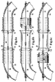
- the air intake device consists of a housing 10, which with a Flange 11 is provided for attaching the housing to a not shown here Internal combustion engine.
- a rigid intake pipe 12 arranged in the housing 10. Close this intake pipe two movable intake pipe segments 13, 14. These are intake pipe segments rotatably supported at a common pivot point 15.
- the attachment of the Intake pipe segments 13, 14 take place via a suitable support structure 16, 17.
- the intake pipe segments 13, 14 are apart spaced, i.e. the intake air for the internal combustion engine flows according to the arrow 19a in the intake pipe 12 and from there to the internal combustion engine. This position is the so-called power position and is achieved at high speeds the internal combustion engine has a high torque.
- Figure 1 b shows the air intake device, in which the intake pipe segment 13 the intake pipe 12 is coupled. Corresponding coupling seals 18 are provided for this intended. Now the air flows according to the arrow 19b over the intake pipe segment 13 and the intake pipe 12 in the internal combustion engine. This Position ensures optimum torque, especially at low engine speeds.
- FIG. 1 c shows the coupling of the intake pipe segment 14 to the segment 13 and the intake pipe 12. Now the air flows into the Internal combustion engine. Suitable seals between the individual segments ensure a reliable seal.
- Figures 2 a - c show a first variant of the air intake device.
- Length variables are between the individual segments 13, 14 and the intake pipe 12 Seals 20, 21 are provided. In the position shown in Figure 2a the air intake device has the longest intake path.
- FIG. 2 b shows the decoupling of the segment 14. At the same time, the segment is 13 partially immersed in the intake pipe 12.
- FIG 3 a - c shows a further variant of an air intake device.
- segment 14 is arranged rigidly in the housing 10.
- flexible connection areas 22, 23 are provided on the suction pipe 12.
- the Swiveling of the segment 13 causes it to be compressed or stretched Connection areas and thus, as shown in Figure 3 b, an opening between the Segment 13 and the segment 14 and, as shown in Figure 3 c, an opening between the intake pipe 12 and the segment 13.
- FIGS 4 a - c show an air intake device with a flat housing structure.
- the housing 24 has a segment 25 and an intake pipe 26 Mistake.
- a pivot element 27 is rotatably mounted in the housing.
- One turn of the swivel element 27 counterclockwise leads to a compression of the suction area 22 and at the same time to an opening between the Segment 25 and the pivot element 27.
- a rotation of this pivot element 27 in the clockwise direction leads to a compression of the connection area 23 and to open the intake pipe 26. In this position, the Intake air directly into the short intake pipe.
- FIG. 5 a - c show a suction device with a longitudinally displaceable intermediate element.
- the intermediate element 28 is a piston 29 according to the arrow 30 moved lengthways. In the position shown in Figure 5 a, it connects the intake pipe 31 with the element 32.
- the intermediate element is pushed in the opposite direction and opens the intake pipe 31 for a short intake duct.
- Figure 6 a - c shows a detailed view of the intermediate element described in Figure 5 28.
- This intermediate element has opening funnels at its axial ends 33, 34, the flexible ends of the in the position shown in Figure 6 a take up two pipe sections 35, 36.
- the intermediate element 28 is in the shown example rigidly arranged. This means that none of the Pipe sections is movably mounted. Only the flexible ends of the two Pipes 35, 36 are longitudinally displaceable via slide 37, 38.
- Figure 6 b shows a movement of the slide 37 to the right. This will make a Channel 39 open.
- FIG. 6 c shows a movement of the slide 38 to the left. This will make the channel 40 open.
- FIG. 7 shows a system with an axially movable intermediate element 28.
- Figure 7 a shows the intermediate element in a position pushed to the left.
- the Sealing between the intermediate element 28 and the tube 41 takes place via a Radial seal 42 and a pressurized spring 43 Sealing element 44.
- FIG. 7 b shows the intermediate element 28 in a position pushed to the right.
- the sealing is done as on the opposite side using a Compression spring 45, a sealing element 46 and a radial seal 47.
- Figure 7 c shows the intermediate element 28 in the central position, in which on both sides sealing takes place.
Landscapes
- Engineering & Computer Science (AREA)
- Chemical & Material Sciences (AREA)
- Combustion & Propulsion (AREA)
- Mechanical Engineering (AREA)
- General Engineering & Computer Science (AREA)
- Health & Medical Sciences (AREA)
- Biomedical Technology (AREA)
- Characterised By The Charging Evacuation (AREA)
- Lubrication Details And Ventilation Of Internal Combustion Engines (AREA)
Abstract
Description
- Figuren 1 a - c
- zeigen eine Luftansaugvorrichtung mit zwei beweglichen Segmenten,
- Figuren 2 a - c
- zeigen eine erste Variante der Luftansaugvorrichtung,
- Figuren 3a - c
- zeigen eine weitere Variante einer Luftansaugvorrichtung,
- Figuren 4 a - c
- zeigen eine Luftansaugvorrichtung mit einem flachen Gehäuseaufbau,
- Figuren 5 a - c
- zeigen eine Ansaugvorrichtung mit längs verschieblichem Zwischenelement,
- Figuren 6 a - c
- zeigen eine Detailansicht des in Figur 5 beschriebenen Zwischenelements,
- Figuren 7 a - c
- zeigen ein System mit einem axial beweglichen Zwischenelement.
Claims (5)
- Luftansaugvorrichtung für Brennkraftmaschinen mit wenigstens einem Sammelbehälter und getrennt zu den einzelnen Zylindern der Brennkraftmaschine abzweigende Ansaugleitungen, wobei die Ansaugleitungen sich bis in den Sammelbehälter erstrecken und wenigstens teilweise aus einem flexiblen Element gebildet sind, dadurch gekennzeichnet, daß die Ansaugleitungen starre oder längenvariable Bereiche aufweisen und diese Bereiche in wenigstens zwei, voneinander unabhängig beweglich angeordnete Segmente (13, 14) unterteilt sind.
- Luftansaugvorrichtung nach Anspruch 1, dadurch gekennzeichnet, daß die Segmente (13, 14) an einem gemeinsamen Drehpunkt (15) gelagert sind.
- Luftansaugvorrichtung nach Anspruch 1, dadurch gekennzeichnet, daß Segmente (28) längsverschieblich angeordnet sind.
- Luftansaugvorrichtung nach einem der vorherigen Ansprüche, dadurch gekennzeichnet, daß die Segmente Koppelstellen 18) aufweisen, welche mit Radial- und/oder Axialdichtungen versehen sind.
- Luftansaugvorrichtung nach einem der vorherigen Ansprüche, dadurch gekennzeichnet, daß das an den Zylinderkopf einer Brennkraftmaschine anflanschbare erste Element ein starres Element (16) ist, das nachfolgende Element ein dreh- oder längsbewegliches Element (27) das nachfolgende Element ein starres Element (25) ist und das dreh- oder längsbewegliche Element an den Koppelstellen längenvariable Bereiche aufweist.
Applications Claiming Priority (2)
| Application Number | Priority Date | Filing Date | Title |
|---|---|---|---|
| DE19951083 | 1999-10-23 | ||
| DE19951083A DE19951083A1 (de) | 1999-10-23 | 1999-10-23 | Luftansaugvorrichtung |
Publications (2)
| Publication Number | Publication Date |
|---|---|
| EP1094209A1 true EP1094209A1 (de) | 2001-04-25 |
| EP1094209B1 EP1094209B1 (de) | 2005-04-27 |
Family
ID=7926627
Family Applications (1)
| Application Number | Title | Priority Date | Filing Date |
|---|---|---|---|
| EP00122410A Expired - Lifetime EP1094209B1 (de) | 1999-10-23 | 2000-10-13 | Luftansaugvorrichtung |
Country Status (5)
| Country | Link |
|---|---|
| US (1) | US6408810B1 (de) |
| EP (1) | EP1094209B1 (de) |
| JP (1) | JP2001152988A (de) |
| AT (1) | ATE294323T1 (de) |
| DE (2) | DE19951083A1 (de) |
Cited By (1)
| Publication number | Priority date | Publication date | Assignee | Title |
|---|---|---|---|---|
| EP1818523A1 (de) * | 2006-02-14 | 2007-08-15 | Mazda Motor Corporation | Steuerung eines Motoreinlasssystems |
Families Citing this family (24)
| Publication number | Priority date | Publication date | Assignee | Title |
|---|---|---|---|---|
| DE10139302C1 (de) * | 2001-08-09 | 2003-02-20 | Pierburg Gmbh | Luftansaugkanalsystem für Brennkraftmaschinen |
| US6983727B2 (en) * | 2002-03-19 | 2006-01-10 | Siemens Vdo Automotive Inc. | Continuously variable intake manifold with intelligent position control |
| DE10215604A1 (de) * | 2002-04-10 | 2003-10-30 | Pierburg Gmbh | Luftansaugkanalsystem für Brennkraftmaschinen |
| DE10228569B4 (de) * | 2002-06-26 | 2006-02-09 | Siemens Ag | Ansaugvorrichtung |
| DE10245110B4 (de) * | 2002-09-27 | 2004-07-22 | Siemens Ag | Ansaugeinrichtung |
| DE102004005135B4 (de) * | 2004-02-02 | 2006-02-02 | Siemens Ag | Ansaugkrümmer mit kontinuierlich variabler Kanal-Resonator-Kombination |
| US7117974B2 (en) * | 2004-05-14 | 2006-10-10 | Visteon Global Technologies, Inc. | Electronically controlled dual chamber variable resonator |
| US20060086564A1 (en) * | 2004-10-21 | 2006-04-27 | Visteon Global Technologies, Inc. | Dual chamber variable geometry resonator |
| FR2889256A1 (fr) * | 2005-07-29 | 2007-02-02 | Renault Sas | Ligne d'admission d'air d'un moteur a combustion interne a geometrie variable |
| CN100491709C (zh) * | 2005-10-08 | 2009-05-27 | 顾纯慧 | 一种发动机可变进气系统 |
| JP5027469B2 (ja) * | 2006-01-17 | 2012-09-19 | ヤマハ発動機株式会社 | 車両 |
| JP4772629B2 (ja) * | 2006-01-17 | 2011-09-14 | ヤマハ発動機株式会社 | 車両 |
| JP4781952B2 (ja) | 2006-01-17 | 2011-09-28 | ヤマハ発動機株式会社 | 車両 |
| JP4842066B2 (ja) | 2006-04-14 | 2011-12-21 | ヤマハ発動機株式会社 | 車両 |
| JP4896643B2 (ja) | 2006-04-14 | 2012-03-14 | ヤマハ発動機株式会社 | 車両 |
| US7650867B2 (en) * | 2006-05-11 | 2010-01-26 | Williams Allan R | Intake and exhaust tuning system |
| JP4857059B2 (ja) * | 2006-07-20 | 2012-01-18 | ヤマハ発動機株式会社 | 吸気制御装置、及び吸気制御装置を備える鞍乗型車両 |
| JP2008075523A (ja) * | 2006-09-20 | 2008-04-03 | Yamaha Motor Co Ltd | 吸気制御装置、鞍乗型車両、及び切換条件設定方法 |
| DE102006054270A1 (de) * | 2006-11-17 | 2008-05-21 | Veritas Ag | Baugruppe, umfassend einen Abgasturbolader, einen Ladeluftkühler und eine Ladeluftleitung |
| JP2008128154A (ja) * | 2006-11-24 | 2008-06-05 | Yamaha Motor Co Ltd | 車両 |
| DE102014007569A1 (de) | 2014-05-22 | 2015-11-26 | Daimler Ag | Luftansaugeinrichtung für eine Verbrennungskraftmaschine, insbesondere eines Kraftwagens |
| DE102016002132A1 (de) | 2016-02-23 | 2017-08-24 | Ulrich Streuer | Ansaugsanlage für eine Brennkraftmaschine mit stufenlos einstellbaren Schwingrohren |
| CN107013386B (zh) * | 2017-06-14 | 2023-05-16 | 四川工业科技学院 | 一种发动机可变进气歧管 |
| DE102020112461B4 (de) * | 2020-05-07 | 2022-08-11 | Röchling Automotive SE & Co. KG | Luftansaugvorrichtung mit einem längenveränderlichen Ansaugkanal und gesonderter Zentriervorrichtung |
Citations (4)
| Publication number | Priority date | Publication date | Assignee | Title |
|---|---|---|---|---|
| US4543918A (en) * | 1982-12-24 | 1985-10-01 | Ford Motor Company | Intake manifold for an internal combustion engine |
| JPH08326546A (ja) * | 1995-05-31 | 1996-12-10 | Mitsubishi Motors Corp | エンジンの吸気管長可変装置 |
| DE19729217A1 (de) * | 1997-07-09 | 1999-06-10 | Mann & Hummel Filter | Luftansaugvorrichtung für Brennkraftmaschinen |
| DE19841810A1 (de) * | 1998-09-12 | 2000-03-23 | Porsche Ag | Schaltbare Luftsauganlage für Brennkraftmaschinen |
Family Cites Families (5)
| Publication number | Priority date | Publication date | Assignee | Title |
|---|---|---|---|---|
| DE3630488A1 (de) * | 1985-09-19 | 1987-03-26 | Volkswagen Ag | Laengenveraenderbares saugrohr fuer eine brennkraftmaschine |
| DE3807159A1 (de) * | 1988-03-04 | 1989-09-14 | Bayerische Motoren Werke Ag | Saugrohr einer brennkraftmaschine |
| JP3261964B2 (ja) * | 1996-02-16 | 2002-03-04 | トヨタ自動車株式会社 | 内燃機関の可変吸気装置 |
| DE19717272A1 (de) * | 1996-05-04 | 1997-11-06 | Volkswagen Ag | Luftansauganlage für eine Brennkraftmaschine |
| DE19728600C2 (de) * | 1997-07-04 | 2003-02-27 | Bosch Gmbh Robert | Sauganlage für eine Brennkraftmaschine |
-
1999
- 1999-10-23 DE DE19951083A patent/DE19951083A1/de not_active Withdrawn
-
2000
- 2000-10-13 EP EP00122410A patent/EP1094209B1/de not_active Expired - Lifetime
- 2000-10-13 DE DE50010150T patent/DE50010150D1/de not_active Expired - Fee Related
- 2000-10-13 AT AT00122410T patent/ATE294323T1/de not_active IP Right Cessation
- 2000-10-20 JP JP2000321400A patent/JP2001152988A/ja active Pending
- 2000-10-23 US US09/693,907 patent/US6408810B1/en not_active Expired - Fee Related
Patent Citations (4)
| Publication number | Priority date | Publication date | Assignee | Title |
|---|---|---|---|---|
| US4543918A (en) * | 1982-12-24 | 1985-10-01 | Ford Motor Company | Intake manifold for an internal combustion engine |
| JPH08326546A (ja) * | 1995-05-31 | 1996-12-10 | Mitsubishi Motors Corp | エンジンの吸気管長可変装置 |
| DE19729217A1 (de) * | 1997-07-09 | 1999-06-10 | Mann & Hummel Filter | Luftansaugvorrichtung für Brennkraftmaschinen |
| DE19841810A1 (de) * | 1998-09-12 | 2000-03-23 | Porsche Ag | Schaltbare Luftsauganlage für Brennkraftmaschinen |
Non-Patent Citations (1)
| Title |
|---|
| PATENT ABSTRACTS OF JAPAN vol. 1997, no. 04 30 April 1997 (1997-04-30) * |
Cited By (2)
| Publication number | Priority date | Publication date | Assignee | Title |
|---|---|---|---|---|
| EP1818523A1 (de) * | 2006-02-14 | 2007-08-15 | Mazda Motor Corporation | Steuerung eines Motoreinlasssystems |
| US7444975B2 (en) | 2006-02-14 | 2008-11-04 | Mazda Motor Corporation | Control of engine intake system |
Also Published As
| Publication number | Publication date |
|---|---|
| EP1094209B1 (de) | 2005-04-27 |
| ATE294323T1 (de) | 2005-05-15 |
| DE19951083A1 (de) | 2001-04-26 |
| US6408810B1 (en) | 2002-06-25 |
| JP2001152988A (ja) | 2001-06-05 |
| DE50010150D1 (de) | 2005-06-02 |
Similar Documents
| Publication | Publication Date | Title |
|---|---|---|
| EP1094209B1 (de) | Luftansaugvorrichtung | |
| DE69505763T2 (de) | Ansaugrohr mit Schwenkklappen für eine Brennkraftmaschine | |
| DE4423427C2 (de) | Ansauganlage für eine Mehrzylinder-Brennkraftmaschine | |
| DE102011108728B4 (de) | Ventiltrieb für Brennkraftmaschinen zur Betätigung von Gaswechselventilen | |
| DE102007033675A1 (de) | Abgasrückführvorrichtung für eine Verbrennungskraftmaschine | |
| DE4041200C2 (de) | Luftansauganlage fuer eine brennkraftmaschine | |
| DE102008024876A1 (de) | Ventiltrieb für Gaswechselventile einer Brennkraftmaschine mit verschiebbaren, stirnseitig gelagerten Nockenträgern | |
| DE202007013151U1 (de) | Ansaugsystem für eine Brennkraftmaschine | |
| DE102018217435A1 (de) | Verstelleinrichtung mit wenigstens einer Führungseinrichtung für die Verstellung mehrerer Leitschaufeln eines Triebwerks | |
| DE4039992C2 (de) | ||
| DE102008024875A1 (de) | Ventiltrieb für Gaswechselventile einer Brennkraftmaschine mit verschiebbaren Nockenträgern und gegenseitiger Abstützung benachbarter Nockenträger | |
| DE102012001303B4 (de) | Verstellwellenbetätigung eines Ventiltriebs für Brennkraftmaschinen zur Betätigung von Gaswechselventilen | |
| DE4028489B4 (de) | Luftangsaugeinrichtung für eine Brennkraftmaschine | |
| DE102004003208A1 (de) | Verdichter im Ansaugtrakt einer Brennkraftmaschine | |
| DE19506306A1 (de) | Ansaugvorrichtung für eine Kolbenbrennkraftmaschine | |
| DE102017210661A1 (de) | Ventiltriebvorrichtung für eine mehrzylindrige Brennkraftmaschine | |
| DE3338596A1 (de) | Auspuffbremsventil | |
| DE19841810A1 (de) | Schaltbare Luftsauganlage für Brennkraftmaschinen | |
| DE102007017153A1 (de) | Hubkolben-Verbrennungsmotor mit variabler Verdichtung | |
| DE102013021611B4 (de) | Brennkraftmaschine mit einem Saugrohr | |
| WO1997013060A1 (de) | Ansauganlage für eine mehrzylinderbrennkraftmaschine | |
| DE102011115788B4 (de) | Verstellwellenbetätigung eines Ventiltriebs für Brennkraftmaschinen zur Betätigung von Gaswechselventilen | |
| DE102007039108B4 (de) | Lufteinlasseinrichtung für eine Brennkraftmaschine | |
| DE19820245A1 (de) | Ansaugsystem für eine Brennkraftmaschine | |
| DE102007054953A1 (de) | Luftgekühlter Abgasrückführkühler |
Legal Events
| Date | Code | Title | Description |
|---|---|---|---|
| PUAI | Public reference made under article 153(3) epc to a published international application that has entered the european phase |
Free format text: ORIGINAL CODE: 0009012 |
|
| AK | Designated contracting states |
Kind code of ref document: A1 Designated state(s): AT BE CH CY DE DK ES FI FR GB GR IE IT LI LU MC NL PT SE |
|
| AX | Request for extension of the european patent |
Free format text: AL;LT;LV;MK;RO;SI |
|
| 17P | Request for examination filed |
Effective date: 20010528 |
|
| AKX | Designation fees paid |
Free format text: AT BE CH CY DE DK ES FI FR GB GR IE IT LI LU MC NL PT SE |
|
| RAP1 | Party data changed (applicant data changed or rights of an application transferred) |
Owner name: MANN + HUMMEL GMBH |
|
| 17Q | First examination report despatched |
Effective date: 20040607 |
|
| GRAP | Despatch of communication of intention to grant a patent |
Free format text: ORIGINAL CODE: EPIDOSNIGR1 |
|
| GRAS | Grant fee paid |
Free format text: ORIGINAL CODE: EPIDOSNIGR3 |
|
| GRAA | (expected) grant |
Free format text: ORIGINAL CODE: 0009210 |
|
| AK | Designated contracting states |
Kind code of ref document: B1 Designated state(s): AT BE CH CY DE DK ES FI FR GB GR IE IT LI LU MC NL PT SE |
|
| PG25 | Lapsed in a contracting state [announced via postgrant information from national office to epo] |
Ref country code: IT Free format text: LAPSE BECAUSE OF FAILURE TO SUBMIT A TRANSLATION OF THE DESCRIPTION OR TO PAY THE FEE WITHIN THE PRESCRIBED TIME-LIMIT;WARNING: LAPSES OF ITALIAN PATENTS WITH EFFECTIVE DATE BEFORE 2007 MAY HAVE OCCURRED AT ANY TIME BEFORE 2007. THE CORRECT EFFECTIVE DATE MAY BE DIFFERENT FROM THE ONE RECORDED. Effective date: 20050427 Ref country code: FI Free format text: LAPSE BECAUSE OF FAILURE TO SUBMIT A TRANSLATION OF THE DESCRIPTION OR TO PAY THE FEE WITHIN THE PRESCRIBED TIME-LIMIT Effective date: 20050427 Ref country code: NL Free format text: LAPSE BECAUSE OF FAILURE TO SUBMIT A TRANSLATION OF THE DESCRIPTION OR TO PAY THE FEE WITHIN THE PRESCRIBED TIME-LIMIT Effective date: 20050427 Ref country code: IE Free format text: LAPSE BECAUSE OF FAILURE TO SUBMIT A TRANSLATION OF THE DESCRIPTION OR TO PAY THE FEE WITHIN THE PRESCRIBED TIME-LIMIT Effective date: 20050427 |
|
| REG | Reference to a national code |
Ref country code: GB Ref legal event code: FG4D Free format text: NOT ENGLISH |
|
| REG | Reference to a national code |
Ref country code: CH Ref legal event code: EP |
|
| REG | Reference to a national code |
Ref country code: IE Ref legal event code: FG4D Free format text: LANGUAGE OF EP DOCUMENT: GERMAN |
|
| REF | Corresponds to: |
Ref document number: 50010150 Country of ref document: DE Date of ref document: 20050602 Kind code of ref document: P |
|
| PG25 | Lapsed in a contracting state [announced via postgrant information from national office to epo] |
Ref country code: SE Free format text: LAPSE BECAUSE OF FAILURE TO SUBMIT A TRANSLATION OF THE DESCRIPTION OR TO PAY THE FEE WITHIN THE PRESCRIBED TIME-LIMIT Effective date: 20050727 Ref country code: DK Free format text: LAPSE BECAUSE OF FAILURE TO SUBMIT A TRANSLATION OF THE DESCRIPTION OR TO PAY THE FEE WITHIN THE PRESCRIBED TIME-LIMIT Effective date: 20050727 Ref country code: GR Free format text: LAPSE BECAUSE OF FAILURE TO SUBMIT A TRANSLATION OF THE DESCRIPTION OR TO PAY THE FEE WITHIN THE PRESCRIBED TIME-LIMIT Effective date: 20050727 |
|
| PG25 | Lapsed in a contracting state [announced via postgrant information from national office to epo] |
Ref country code: ES Free format text: LAPSE BECAUSE OF FAILURE TO SUBMIT A TRANSLATION OF THE DESCRIPTION OR TO PAY THE FEE WITHIN THE PRESCRIBED TIME-LIMIT Effective date: 20050807 |
|
| GBT | Gb: translation of ep patent filed (gb section 77(6)(a)/1977) |
Effective date: 20050815 |
|
| PG25 | Lapsed in a contracting state [announced via postgrant information from national office to epo] |
Ref country code: PT Free format text: LAPSE BECAUSE OF FAILURE TO SUBMIT A TRANSLATION OF THE DESCRIPTION OR TO PAY THE FEE WITHIN THE PRESCRIBED TIME-LIMIT Effective date: 20051010 |
|
| PG25 | Lapsed in a contracting state [announced via postgrant information from national office to epo] |
Ref country code: AT Free format text: LAPSE BECAUSE OF NON-PAYMENT OF DUE FEES Effective date: 20051013 Ref country code: CY Free format text: LAPSE BECAUSE OF FAILURE TO SUBMIT A TRANSLATION OF THE DESCRIPTION OR TO PAY THE FEE WITHIN THE PRESCRIBED TIME-LIMIT Effective date: 20051013 |
|
| PG25 | Lapsed in a contracting state [announced via postgrant information from national office to epo] |
Ref country code: CH Free format text: LAPSE BECAUSE OF NON-PAYMENT OF DUE FEES Effective date: 20051031 Ref country code: LI Free format text: LAPSE BECAUSE OF NON-PAYMENT OF DUE FEES Effective date: 20051031 Ref country code: LU Free format text: LAPSE BECAUSE OF NON-PAYMENT OF DUE FEES Effective date: 20051031 Ref country code: BE Free format text: LAPSE BECAUSE OF NON-PAYMENT OF DUE FEES Effective date: 20051031 Ref country code: MC Free format text: LAPSE BECAUSE OF NON-PAYMENT OF DUE FEES Effective date: 20051031 |
|
| NLV1 | Nl: lapsed or annulled due to failure to fulfill the requirements of art. 29p and 29m of the patents act | ||
| REG | Reference to a national code |
Ref country code: IE Ref legal event code: FD4D |
|
| PLBE | No opposition filed within time limit |
Free format text: ORIGINAL CODE: 0009261 |
|
| STAA | Information on the status of an ep patent application or granted ep patent |
Free format text: STATUS: NO OPPOSITION FILED WITHIN TIME LIMIT |
|
| ET | Fr: translation filed | ||
| 26N | No opposition filed |
Effective date: 20060130 |
|
| REG | Reference to a national code |
Ref country code: CH Ref legal event code: PL |
|
| PGFP | Annual fee paid to national office [announced via postgrant information from national office to epo] |
Ref country code: DE Payment date: 20061023 Year of fee payment: 7 Ref country code: GB Payment date: 20061023 Year of fee payment: 7 |
|
| BERE | Be: lapsed |
Owner name: MANN + HUMMEL G.M.B.H. Effective date: 20051031 |
|
| GBPC | Gb: european patent ceased through non-payment of renewal fee |
Effective date: 20071013 |
|
| PG25 | Lapsed in a contracting state [announced via postgrant information from national office to epo] |
Ref country code: DE Free format text: LAPSE BECAUSE OF NON-PAYMENT OF DUE FEES Effective date: 20080501 |
|
| REG | Reference to a national code |
Ref country code: FR Ref legal event code: ST Effective date: 20080630 |
|
| PGFP | Annual fee paid to national office [announced via postgrant information from national office to epo] |
Ref country code: FR Payment date: 20061016 Year of fee payment: 7 |
|
| PG25 | Lapsed in a contracting state [announced via postgrant information from national office to epo] |
Ref country code: GB Free format text: LAPSE BECAUSE OF NON-PAYMENT OF DUE FEES Effective date: 20071013 |
|
| PG25 | Lapsed in a contracting state [announced via postgrant information from national office to epo] |
Ref country code: FR Free format text: LAPSE BECAUSE OF NON-PAYMENT OF DUE FEES Effective date: 20071031 |