EP1094128B1 - Verfahren zur Innenbeschichtung von Hohlkörpern - Google Patents
Verfahren zur Innenbeschichtung von Hohlkörpern Download PDFInfo
- Publication number
- EP1094128B1 EP1094128B1 EP19990121189 EP99121189A EP1094128B1 EP 1094128 B1 EP1094128 B1 EP 1094128B1 EP 19990121189 EP19990121189 EP 19990121189 EP 99121189 A EP99121189 A EP 99121189A EP 1094128 B1 EP1094128 B1 EP 1094128B1
- Authority
- EP
- European Patent Office
- Prior art keywords
- gas
- hollow body
- working
- outlet
- inlet
- Prior art date
- Legal status (The legal status is an assumption and is not a legal conclusion. Google has not performed a legal analysis and makes no representation as to the accuracy of the status listed.)
- Expired - Lifetime
Links
- 238000000034 method Methods 0.000 title claims description 15
- 239000011248 coating agent Substances 0.000 title claims description 6
- 238000000576 coating method Methods 0.000 title claims description 6
- 239000007789 gas Substances 0.000 claims description 104
- 238000009832 plasma treatment Methods 0.000 claims description 12
- 238000010586 diagram Methods 0.000 description 4
- 238000005259 measurement Methods 0.000 description 3
- 239000000126 substance Substances 0.000 description 3
- 230000004888 barrier function Effects 0.000 description 2
- 238000005253 cladding Methods 0.000 description 2
- 230000000712 assembly Effects 0.000 description 1
- 238000000429 assembly Methods 0.000 description 1
- 238000007796 conventional method Methods 0.000 description 1
- 230000007423 decrease Effects 0.000 description 1
- 230000000694 effects Effects 0.000 description 1
- 239000000463 material Substances 0.000 description 1
- 239000003758 nuclear fuel Substances 0.000 description 1
- 238000005086 pumping Methods 0.000 description 1
Images


Classifications
-
- C—CHEMISTRY; METALLURGY
- C23—COATING METALLIC MATERIAL; COATING MATERIAL WITH METALLIC MATERIAL; CHEMICAL SURFACE TREATMENT; DIFFUSION TREATMENT OF METALLIC MATERIAL; COATING BY VACUUM EVAPORATION, BY SPUTTERING, BY ION IMPLANTATION OR BY CHEMICAL VAPOUR DEPOSITION, IN GENERAL; INHIBITING CORROSION OF METALLIC MATERIAL OR INCRUSTATION IN GENERAL
- C23C—COATING METALLIC MATERIAL; COATING MATERIAL WITH METALLIC MATERIAL; SURFACE TREATMENT OF METALLIC MATERIAL BY DIFFUSION INTO THE SURFACE, BY CHEMICAL CONVERSION OR SUBSTITUTION; COATING BY VACUUM EVAPORATION, BY SPUTTERING, BY ION IMPLANTATION OR BY CHEMICAL VAPOUR DEPOSITION, IN GENERAL
- C23C16/00—Chemical coating by decomposition of gaseous compounds, without leaving reaction products of surface material in the coating, i.e. chemical vapour deposition [CVD] processes
- C23C16/04—Coating on selected surface areas, e.g. using masks
- C23C16/045—Coating cavities or hollow spaces, e.g. interior of tubes; Infiltration of porous substrates
Definitions
- the invention relates to a method for the controlled guidance of the plasma treatment Complex hollow body geometries necessary working gases, in which the working gases on at least one inlet and at least one outlet in or out of the inside to be coated Hollow body are guided in mutual flow.
- FR-A-2 695 506 it is known in a plasma-assisted coating of the Inner surface of cladding for nuclear fuel the end-side areas of the To use cladding alternately for generating the plasma and for pumping and a generate mutual flow of the working gas.
- the invention is therefore based on the object, a method of the type mentioned To provide an optimized working gas guidance and control to the Plasma treatment of complex hollow body geometries for the purpose of uniform treatment or Coating the inner surface of the hollow body to be ensured in a constant thickness.
- the reciprocal working gas flow (countercurrent) over the duration of the plasma treatment between the at least one inlet and the spaced therefrom at least one outlet is generated by during a first treatment time t a, the supply and the discharge the working gas via the inlet or the outlet spaced therefrom and the working gas is deposited as a first treatment layer a in the hollow body, and that during an immediately subsequent second treatment time t b by switching the supply and the discharge of the working gas through the outlet or the inlet takes place and the working gas is discharged as a second treatment layer b in the hollow body, which generates a sum total with the first treatment layer a a uniform total treatment layer a + b on the inner wall of the hollow body, wherein the opening cross-sections the at least one inlet and the at least one outlet of the working gas are controlled as a function of the respective residence time t a and t b of the working gases in the hollow body.
- the counterflow of the working gas over the duration of Plasema opposition generated alternately.
- tubular hollow bodies in the immediate vicinity of the at least one gas outlet and the spaced therefrom at least one gas outlet on the hollow body in a paired arrangement in each case another Gas inlet or a gas outlet are provided, over the treatment time t the respective mutually associated gas inlets and gas outlets of the paired assemblies be released, the working gases in the alternating countercurrent principle in the Become hollow body and executed and the entire inner surface of the hollow body is evenly coated.
- hoses or Tubes are used, which via corresponding Abdic htungen from the working chamber after be led outside.
- the control of the working gas supply, in particular the gas flow can be realized outside or inside the working chamber via control systems.
- the outlets of the working gas, which are controllable via appropriate tax systems, can directly from the Working chamber or lead via hoses or pipes to a vacuum suction preferred the control of the working gas flow into and out of the inlets or outlets e.g. as trapezoidal function, Ramp function, sawtooth function or sine function.
- the inventive method made possible by the controlled mutual flow or Counterflow of the working gas in the hollow body a particularly uniform coating the inner surface of the latter, such as permeation measurements on plasma polymerized tubes have proven. Furthermore, by the invention advantageously long or Compensated for complex gas lines, which are given by appropriate hollow body geometries are. Thus, by the mutual circuit of the associated Working gas supplies and discharges of the corresponding pairwise arrangements treated inner surface of the hollow body subjected to a very uniform treatment as detailed research has shown.
- Fig. 1 illustrates a preferred embodiment of the invention, according to the one another opposite, enlarged in cross-section ends 4 of a tubular hollow body 3 a Paired arrangement of a gas inlet 1 and a gas outlet 6 on the one hand and in pairs Arrangement of a gas inlet 5 and a gas outlet 2 on the other hand be provided, so that a mutual flow or countercurrent of the working gas can be generated, and although from the gas inlet 1 to the gas outlet 2 on the one hand and from the gas inlet 5 to the gas outlet. 6 on the other hand.
- the gas inlet 1 and the gas outlet 2 and the gas inlet 5 and the gas outlet 6 of the respective working gases alternately switched, so that the supply and control of the necessary for the plasma treatment working gases can be optimized by means of the alternating countercurrent principle and the entire plasma-treated inner surface 7 of the hollow body 3 is uniformly coated.
- the permeated percentage amount of substance determined.
- a permeation measurement on plasma polymerized pipes is in Comparison of a plasma treatment of the inner surface of the tubes after the conventional inflow principle and the countercurrent principle of the working gases according to the Invention the percentage permeated amount of material as a measure of the layer quality in the Barrier layers with respect to the eight measuring points of Fig. 1 plotted.
- the working gas was via the gas inlet 1 and discharged via the gas outlet 2.
- the diagram clearly shows that with increasing distance to the working gas supply, the barrier effect decreases, i. the Layer thickness is reduced.
- the permeated amount of substance that in the after Counterflow principle coated inner surface 7 of the hollow body 3 was measured over the total pipe length equal, i. there is a constant layer thickness.
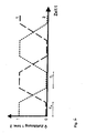
- FIG. 4 shows an example of the Procedure according to FIG. 1, the course of the reciprocal gas supply of the working gas through the respective gas inlets 1 and 5 of the opposite pairwise arrangements over the time of the plasma treatment of the hollow body 3 after such a trapezoidal function.
- FIG. 3 shows a schematic longitudinal sectional view of a normally provided with a gas inlet 1 and a gas outlet 2 tubular hollow body 3, the treatment phases of the hollow body inner surface 7 during the working gas feeds according to the alternating countercurrent principle of Fig. 2 show.
- the treatment time t a (FIG. 3) through the working gas introduced into the hollow body 3 via the gas inlet 1, this separates out as a treatment layer a on the inner surface 7 of the hollow body 3.
- the working gas separates during a treatment time t b (Fig. 3) as a treatment layer b on the inner surface 7 of the hollow body 3, the sum of the treatment layer t a produces a uniform treatment layer a + b on the inner surface 7 of the hollow body 3.
Landscapes
- Chemical & Material Sciences (AREA)
- General Chemical & Material Sciences (AREA)
- Chemical Kinetics & Catalysis (AREA)
- Engineering & Computer Science (AREA)
- Materials Engineering (AREA)
- Mechanical Engineering (AREA)
- Metallurgy (AREA)
- Organic Chemistry (AREA)
- Chemical Vapour Deposition (AREA)
- Physical Or Chemical Processes And Apparatus (AREA)
Description
Claims (7)
- Verfahren zur gesteuerten Führung von für die Plasmabehandlung komplexer Hohlkörpergeometrien notwendiger Arbeitsgase, bei dem die Arbeitsgase über mindestens einen Einlaß und mindestens einen zu diesem beabstandeten Auslaß in bzw. aus dem innen zu beschichtenden Hohlkörper in wechselseitiger Strömung geführt werden, dadurch gekennzeichnet, daß in dem Hohlkörper (3) die wechselseitige Arbeitsgasströmung (Gegenströmung) über die Dauer der Plasmabehandlung zwischen dem mindestens einen Einlaß (1) und dem zu diesem beabstandeten mindestens einen Auslaß (2) erzeugt wird, indem während einer ersten Behandlungszeit (ta) die Zuführung und die Abführung des Arbeitsgases über den Einlaß (1) bzw. den zu diesem beabstandeten Auslaß (2) erfolgt und das Arbeitsgas sich als eine erste Behandlungsschicht (a) im Hohlkörper (3) abscheidet, und daß während einer sich unmittelbar anschließenden zweiten Behandlungszeit (tb) durch Umschaltung der Zuführung und der Abführung des Arbeitsgases diese über den Auslaß (2) bzw. den Einlaß (1) erfolgen und das Arbeitsgas sich als eine zweite Behandlungsschicht (b) im Hohlkörper (3) abscheidet, die als Summe mit der ersten Behandlungsschicht (a) eine gleichmäßige Gesamtbehandlungsschicht (a + b) auf der Innenwand (7) des Hohlkörpers (3) erzeugt, wobei die Öffnungsquerschnitte des mindestens einen Einlasses (1) und des mindestens einen Auslasses (2) des Arbeitsgases in Abhängigkeit von der jeweiligen notwendigen Verweilszeit (ta und tb) der Arbeitsgase im Hohlkörper (3) gesteuert werden.
- Verfahren nach Anspruch 1, dadurch gekennzeichnet, daß in unmittelbarer Nähe des mindestens einen Gaseinlasses (1) und des zu diesem beabstandeten, mindestens einen Gasauslasses (2) am Hohlkörper (3) in paarweiser Anordnung jeweils ein weiterer Gasauslaß (5) bzw. ein Gaseinlaß (6) vorgesehen wird, und daß über die Beschichtungszeit (t) die jeweils einander zugeordneten Gaseinlässe (1; 5) und Gasauslässe (2; 6) der paarweisen Anordnungen (1, 2; 5, 6) wechselseitig freigeschaltet werden und die Arbeitsgase dabei im alternierenden Gegenstromprinzip in den Hohlkörpers (3) ein- und ausgeführt werden, wobei die gesamte Innenoberfläche (7) des Hohlkörpers (3) gleichmäßig beschichtet wird.
- Verfahren nach Anspruch 2, dadurch gekennzeichnet, daß die Steuerung des Arbeitsgasstroms durch die Gaseinlässe (1; 5) und die Gasauslässe (2; 6) als Trapezfunktion erfolgt.
- Verfahren nach Anspruch 2, dadurch gekennzeichnet, daß die Steuerung des Arbeitsgasstroms durch die Gaseinlässe (1; 5) und die Gasauslässe (2; 6) als Rampenfunktion erfolgt.
- Verfahren nach Anspruch 2, dadurch gekennzeichnet, daß die Steuerung des Arbeitsgastroms durch die Gaseinlässe (1; 5) und die Gasauslässe (2; 6) als Sägezahnfunktion erfolgt.
- Verfahren nach Anspruch 2, dadurch gekennzeichnet, daß die Steuerung des Arbeitsgasstroms durch die Gaseinlässe (1; 5) und die Gasauslässe (2; 6) als Sinusfunktion erfolgt.
- Verfahren nach Anspruch 2 bis 6, dadurch gekennzeichnet, daß eine Vielzahl der paarweisen Anordnung von Gaseinlaß (1; 5) und zugeordnetem Gasauslaß (2; 6) an dem Hohlkörper (3) beabstandet hintereinander vorgesehen wird.
Priority Applications (2)
| Application Number | Priority Date | Filing Date | Title |
|---|---|---|---|
| EP19990121189 EP1094128B1 (de) | 1999-10-22 | 1999-10-22 | Verfahren zur Innenbeschichtung von Hohlkörpern |
| DE59912989T DE59912989D1 (de) | 1999-10-22 | 1999-10-22 | Verfahren zur Innenbeschichtung von Hohlkörpern |
Applications Claiming Priority (1)
| Application Number | Priority Date | Filing Date | Title |
|---|---|---|---|
| EP19990121189 EP1094128B1 (de) | 1999-10-22 | 1999-10-22 | Verfahren zur Innenbeschichtung von Hohlkörpern |
Publications (2)
| Publication Number | Publication Date |
|---|---|
| EP1094128A1 EP1094128A1 (de) | 2001-04-25 |
| EP1094128B1 true EP1094128B1 (de) | 2005-12-28 |
Family
ID=8239270
Family Applications (1)
| Application Number | Title | Priority Date | Filing Date |
|---|---|---|---|
| EP19990121189 Expired - Lifetime EP1094128B1 (de) | 1999-10-22 | 1999-10-22 | Verfahren zur Innenbeschichtung von Hohlkörpern |
Country Status (2)
| Country | Link |
|---|---|
| EP (1) | EP1094128B1 (de) |
| DE (1) | DE59912989D1 (de) |
Families Citing this family (4)
| Publication number | Priority date | Publication date | Assignee | Title |
|---|---|---|---|---|
| WO2002075021A1 (de) * | 2001-03-17 | 2002-09-26 | Gfe Metalle Und Materialien Gmbh | Plasmabeschichtungsverfahren und vorrichtung zur durchführung des verfahrens |
| US7541069B2 (en) * | 2005-03-07 | 2009-06-02 | Sub-One Technology, Inc. | Method and system for coating internal surfaces using reverse-flow cycling |
| US7608151B2 (en) | 2005-03-07 | 2009-10-27 | Sub-One Technology, Inc. | Method and system for coating sections of internal surfaces |
| US7927656B2 (en) * | 2006-08-31 | 2011-04-19 | General Electric Company | Method and apparatus for controlling diffusion coating of internal passages |
Family Cites Families (2)
| Publication number | Priority date | Publication date | Assignee | Title |
|---|---|---|---|---|
| DE1913676A1 (de) * | 1969-03-18 | 1970-09-24 | Siemens Ag | Verfahren zum Abscheiden von Schichten aus halbleitendem bzw. isolierendem Material aus einem stroemenden Reaktionsgas auf erhitzte Halbleiterkristalle bzw. zum Dotieren solcher Kristalle aus einem stroemenden dotierenden Gas |
| FR2695506B1 (fr) * | 1992-09-10 | 1994-10-28 | Pechiney Uranium | Gaine pour combustible nucléaire revêtue de poison neutronique consommable et son procédé d'obtention. |
-
1999
- 1999-10-22 DE DE59912989T patent/DE59912989D1/de not_active Expired - Lifetime
- 1999-10-22 EP EP19990121189 patent/EP1094128B1/de not_active Expired - Lifetime
Also Published As
| Publication number | Publication date |
|---|---|
| DE59912989D1 (de) | 2006-02-02 |
| EP1094128A1 (de) | 2001-04-25 |
Similar Documents
| Publication | Publication Date | Title |
|---|---|---|
| DE2055995C3 (de) | Verfahren zum kontinuierlichen galvanischen Verchromen der Außenoberfläche von Stangen oder Rohren | |
| DE4342914C1 (de) | Verfahren zum Impr{gnieren der Str¦mungskan{le von Wabenk¦rpern mit definierten Konzentrationsprofilen | |
| EP3576884A1 (de) | Applikationssystem zum beschichten von bauteilen und beschichtungseinrichtung | |
| EP0444253B1 (de) | Vorrichtung zum Aufbringen dünner Schichten auf ein Substrat | |
| EP1094128A1 (de) | Verfahren zur Innenbeschichtung von Hohlkörpern | |
| DE102004020185B4 (de) | Verfahren und Vorrichtung für die Innenbeschichtung von Hohlkörpern sowie Verwendung der Vorrichtung | |
| EP1095707A2 (de) | Farbwechselventilanordnung und Verfahren zum Spülen eines Farbwechslers | |
| DE102004021734A1 (de) | Verfahren und Vorrichtung zur kontinuierlichen Beschichtung flacher Substrate mit optisch aktiven Schichtssystemen | |
| DE2637188C3 (de) | Verfahren und Vorrichtung zur Herstellung von Schaumstoffen aus Kunststoff | |
| DE3922601C2 (de) | Verfahren und Vorrichtung zur Niedertemperatur-Plasmabehandlung von textilen Substraten | |
| DE3116026A1 (de) | Verfahren zum herstellen einer biokompatiblen schicht auf der innenseite und/oder auf der aussenseite von schlaeuchen | |
| WO2013004851A1 (de) | Verfahren und vorrichtung zur kontinuierlichen beschichtung von substraten | |
| DE102012111484A1 (de) | Vorrichtung und Verfahren zum Bearbeiten streifenförmiger Substrate | |
| EP0369478B1 (de) | Kammer für die verschiedenen Behandlungsstationen eines Gegenstandes beim elektrostatischen Pulverbeschichten | |
| EP0568910B1 (de) | Verfahren und Vorrichtung zum Reinigen einer Farbbeschichtungseinrichtung | |
| EP0255669A1 (de) | Verfahren und Vorrichtung zur Tauchbeschichtung von Objekten mit flüssigen Beschichtungsmaterialien mit anschliessender Spülung unter Verwendung von Ultrafiltrat | |
| DE102004038017A1 (de) | Verfahren und Vorrichtung für einen zeitlich nacheinander erfolgenden Austrag unterschiedlicher Farben bzw. Lacke | |
| DE102012012467A1 (de) | Vorrichtung zum Auftragen eines Fluids auf einen laufenden Multifilamentfaden | |
| DE19634725A1 (de) | Verfahren und Vorrichtung zur Behandlung von Fasermaterial | |
| DE3830216C2 (de) | ||
| DE3135553A1 (de) | Vorrichtung zum plattieren | |
| DE2951566A1 (de) | Verfahren zur herstellung von schlaeuchen mit einer duennen innenschicht | |
| DE102021105583A1 (de) | Düse zum Auftragen eines Haftmaterials, Applikationsvorrichtung zum Auftragen eines Haftmaterials, Verfahren zum Auftragen eines Haftmaterials sowie Bauteil für ein Fahrzeug | |
| AT403295B (de) | Vorrichtung zum aufspritzen von beiz-/oder spülflüssigkeit | |
| WO2021028333A1 (de) | Vorrichtung zur bauteilreinigung mit einem reinigungsfluid |
Legal Events
| Date | Code | Title | Description |
|---|---|---|---|
| PUAI | Public reference made under article 153(3) epc to a published international application that has entered the european phase |
Free format text: ORIGINAL CODE: 0009012 |
|
| AK | Designated contracting states |
Kind code of ref document: A1 Designated state(s): DE |
|
| AX | Request for extension of the european patent |
Free format text: AL;LT;LV;MK;RO;SI |
|
| 17P | Request for examination filed |
Effective date: 20010920 |
|
| AKX | Designation fees paid |
Free format text: DE |
|
| 17Q | First examination report despatched |
Effective date: 20041103 |
|
| GRAP | Despatch of communication of intention to grant a patent |
Free format text: ORIGINAL CODE: EPIDOSNIGR1 |
|
| GRAS | Grant fee paid |
Free format text: ORIGINAL CODE: EPIDOSNIGR3 |
|
| GRAA | (expected) grant |
Free format text: ORIGINAL CODE: 0009210 |
|
| AK | Designated contracting states |
Kind code of ref document: B1 Designated state(s): DE |
|
| REF | Corresponds to: |
Ref document number: 59912989 Country of ref document: DE Date of ref document: 20060202 Kind code of ref document: P |
|
| PLBE | No opposition filed within time limit |
Free format text: ORIGINAL CODE: 0009261 |
|
| STAA | Information on the status of an ep patent application or granted ep patent |
Free format text: STATUS: NO OPPOSITION FILED WITHIN TIME LIMIT |
|
| 26N | No opposition filed |
Effective date: 20060929 |
|
| REG | Reference to a national code |
Ref country code: DE Ref legal event code: R082 Ref document number: 59912989 Country of ref document: DE |
|
| REG | Reference to a national code |
Ref country code: DE Ref legal event code: R081 Ref document number: 59912989 Country of ref document: DE Owner name: SANOFI-AVENTIS DEUTSCHLAND GMBH, DE Free format text: FORMER OWNER: INPRO INNOVATIONSGESELLSCHAFT FUER FORTGESCHRITTENE PRODUKTIONSSYSTEME IN DER FAHRZEUGINDUSTRIE MBH, 10587 BERLIN, DE Effective date: 20130807 |
|
| PGFP | Annual fee paid to national office [announced via postgrant information from national office to epo] |
Ref country code: DE Payment date: 20181009 Year of fee payment: 20 |
|
| REG | Reference to a national code |
Ref country code: DE Ref legal event code: R071 Ref document number: 59912989 Country of ref document: DE |