EP1093546B1 - Anzeigeeinrichtung - Google Patents
Anzeigeeinrichtung Download PDFInfo
- Publication number
- EP1093546B1 EP1093546B1 EP00926760A EP00926760A EP1093546B1 EP 1093546 B1 EP1093546 B1 EP 1093546B1 EP 00926760 A EP00926760 A EP 00926760A EP 00926760 A EP00926760 A EP 00926760A EP 1093546 B1 EP1093546 B1 EP 1093546B1
- Authority
- EP
- European Patent Office
- Prior art keywords
- housing
- display unit
- unit according
- indicator
- display
- Prior art date
- Legal status (The legal status is an assumption and is not a legal conclusion. Google has not performed a legal analysis and makes no representation as to the accuracy of the status listed.)
- Expired - Lifetime
Links
- 239000000463 material Substances 0.000 claims description 7
- 230000003287 optical effect Effects 0.000 claims description 7
- 238000007789 sealing Methods 0.000 claims description 7
- 238000009877 rendering Methods 0.000 abstract 1
- 230000004913 activation Effects 0.000 description 5
- 239000004020 conductor Substances 0.000 description 5
- 239000012530 fluid Substances 0.000 description 4
- 238000012544 monitoring process Methods 0.000 description 4
- 238000009434 installation Methods 0.000 description 3
- 230000000007 visual effect Effects 0.000 description 3
- 230000006978 adaptation Effects 0.000 description 1
- 230000009286 beneficial effect Effects 0.000 description 1
- 230000000295 complement effect Effects 0.000 description 1
- 238000010276 construction Methods 0.000 description 1
- 238000011161 development Methods 0.000 description 1
- 230000018109 developmental process Effects 0.000 description 1
- 230000000694 effects Effects 0.000 description 1
- 239000013536 elastomeric material Substances 0.000 description 1
- 230000002349 favourable effect Effects 0.000 description 1
- 230000033001 locomotion Effects 0.000 description 1
- 230000000149 penetrating effect Effects 0.000 description 1
- 230000002093 peripheral effect Effects 0.000 description 1
- 238000007493 shaping process Methods 0.000 description 1
- 230000029305 taxis Effects 0.000 description 1
Images



Classifications
-
- G—PHYSICS
- G02—OPTICS
- G02B—OPTICAL ELEMENTS, SYSTEMS OR APPARATUS
- G02B6/00—Light guides; Structural details of arrangements comprising light guides and other optical elements, e.g. couplings
- G02B6/0001—Light guides; Structural details of arrangements comprising light guides and other optical elements, e.g. couplings specially adapted for lighting devices or systems
- G02B6/0011—Light guides; Structural details of arrangements comprising light guides and other optical elements, e.g. couplings specially adapted for lighting devices or systems the light guides being planar or of plate-like form
- G02B6/0013—Means for improving the coupling-in of light from the light source into the light guide
- G02B6/0015—Means for improving the coupling-in of light from the light source into the light guide provided on the surface of the light guide or in the bulk of it
- G02B6/002—Means for improving the coupling-in of light from the light source into the light guide provided on the surface of the light guide or in the bulk of it by shaping at least a portion of the light guide, e.g. with collimating, focussing or diverging surfaces
- G02B6/0021—Means for improving the coupling-in of light from the light source into the light guide provided on the surface of the light guide or in the bulk of it by shaping at least a portion of the light guide, e.g. with collimating, focussing or diverging surfaces for housing at least a part of the light source, e.g. by forming holes or recesses
-
- F—MECHANICAL ENGINEERING; LIGHTING; HEATING; WEAPONS; BLASTING
- F15—FLUID-PRESSURE ACTUATORS; HYDRAULICS OR PNEUMATICS IN GENERAL
- F15B—SYSTEMS ACTING BY MEANS OF FLUIDS IN GENERAL; FLUID-PRESSURE ACTUATORS, e.g. SERVOMOTORS; DETAILS OF FLUID-PRESSURE SYSTEMS, NOT OTHERWISE PROVIDED FOR
- F15B15/00—Fluid-actuated devices for displacing a member from one position to another; Gearing associated therewith
- F15B15/20—Other details, e.g. assembly with regulating devices
- F15B15/28—Means for indicating the position, e.g. end of stroke
- F15B15/2807—Position switches, i.e. means for sensing of discrete positions only, e.g. limit switches
-
- G—PHYSICS
- G01—MEASURING; TESTING
- G01D—MEASURING NOT SPECIALLY ADAPTED FOR A SPECIFIC VARIABLE; ARRANGEMENTS FOR MEASURING TWO OR MORE VARIABLES NOT COVERED IN A SINGLE OTHER SUBCLASS; TARIFF METERING APPARATUS; MEASURING OR TESTING NOT OTHERWISE PROVIDED FOR
- G01D5/00—Mechanical means for transferring the output of a sensing member; Means for converting the output of a sensing member to another variable where the form or nature of the sensing member does not constrain the means for converting; Transducers not specially adapted for a specific variable
- G01D5/12—Mechanical means for transferring the output of a sensing member; Means for converting the output of a sensing member to another variable where the form or nature of the sensing member does not constrain the means for converting; Transducers not specially adapted for a specific variable using electric or magnetic means
- G01D5/14—Mechanical means for transferring the output of a sensing member; Means for converting the output of a sensing member to another variable where the form or nature of the sensing member does not constrain the means for converting; Transducers not specially adapted for a specific variable using electric or magnetic means influencing the magnitude of a current or voltage
- G01D5/142—Mechanical means for transferring the output of a sensing member; Means for converting the output of a sensing member to another variable where the form or nature of the sensing member does not constrain the means for converting; Transducers not specially adapted for a specific variable using electric or magnetic means influencing the magnitude of a current or voltage using Hall-effect devices
- G01D5/145—Mechanical means for transferring the output of a sensing member; Means for converting the output of a sensing member to another variable where the form or nature of the sensing member does not constrain the means for converting; Transducers not specially adapted for a specific variable using electric or magnetic means influencing the magnitude of a current or voltage using Hall-effect devices influenced by the relative movement between the Hall device and magnetic fields
-
- H—ELECTRICITY
- H02—GENERATION; CONVERSION OR DISTRIBUTION OF ELECTRIC POWER
- H02K—DYNAMO-ELECTRIC MACHINES
- H02K11/00—Structural association of dynamo-electric machines with electric components or with devices for shielding, monitoring or protection
- H02K11/20—Structural association of dynamo-electric machines with electric components or with devices for shielding, monitoring or protection for measuring, monitoring, testing, protecting or switching
- H02K11/21—Devices for sensing speed or position, or actuated thereby
- H02K11/215—Magnetic effect devices, e.g. Hall-effect or magneto-resistive elements
-
- G—PHYSICS
- G02—OPTICS
- G02B—OPTICAL ELEMENTS, SYSTEMS OR APPARATUS
- G02B6/00—Light guides; Structural details of arrangements comprising light guides and other optical elements, e.g. couplings
- G02B6/0001—Light guides; Structural details of arrangements comprising light guides and other optical elements, e.g. couplings specially adapted for lighting devices or systems
- G02B6/0011—Light guides; Structural details of arrangements comprising light guides and other optical elements, e.g. couplings specially adapted for lighting devices or systems the light guides being planar or of plate-like form
- G02B6/0081—Mechanical or electrical aspects of the light guide and light source in the lighting device peculiar to the adaptation to planar light guides, e.g. concerning packaging
- G02B6/0095—Light guides as housings, housing portions, shelves, doors, tiles, windows, or the like
-
- H—ELECTRICITY
- H01—ELECTRIC ELEMENTS
- H01H—ELECTRIC SWITCHES; RELAYS; SELECTORS; EMERGENCY PROTECTIVE DEVICES
- H01H2219/00—Legends
- H01H2219/054—Optical elements
- H01H2219/062—Light conductor
- H01H2219/0622—Light conductor only an illuminated ring around keys
Definitions
- the invention relates to a display device for optical Display of a relevant for a drive device Operating state, wherein the drive device one in one Has housing movable drive part.
- a Detect sensor device In the field of fluid actuated drives, for example Working cylinders or other linear drives are common the problem, the relative position between that by fluid power movable drive part and the housing by a Detect sensor device.
- the sensor device it is for example a proximity switch, such as by the applicant under the type designation SME-8-K-LED-230 is distributed.
- a display device in the form of a light emitting diode, which indicates the switching state indicates by pressing the proximity switch lights.
- Such a display device has the disadvantage that it with an unfavorable orientation at the place of use installed drive not or at least not without more is visible. Visual monitoring of the operating status the drive device is thereby difficult.
- a display device which is equipped with a display element which in one along at least 180 ° of a circumference of the housing the drive device extending manner on the housing arranged or to be arranged and that in the housing assigned usage position during its display state emits light distributed over the assigned housing circumference.
- the display element in a post radially outward open recess of the housing is arranged. In this way, protection can be provided if necessary mechanical influences, which is then optimal, when the display element is completely sunk in one Sitting well. It can be provided that the radial outer surface of the display element approximately flush with the adjacent outer surfaces of the housing. A certain bulge can be beneficial to even axially Viewing direction, the display status can be reliably recognized close. If the display element is one Indicator ring, is conveniently fixed in a annular receiving recess.
- the drive device is a electrically and / or fluidically actuated linear drive acts, which has at least one front cover and an adjoining one containing the drive part has tubular body, it is advantageous if that Display element placed between these two components is.
- the display element can have a multiple function and also take on the function of a seal, which connects the two components in a fluid-tight manner. In this way, additional sealing measures can usually be taken to be dispensed with.
- the display element expediently has a Display body with at least partially and preferably overall translucent properties, being preferably consists of plastic material.
- This display body can with one or more lamps, for example Light-emitting diodes, which provide the light for example selectively generate that by appropriate light-guiding Properties of the display body over its entire Length distributed to the outside.
- the display element is expediently suitable Interface equipped through which the infeed of the Light-producing signal is possible.
- This can it is an electrical interface over which electrical actuation signals are fed due to whose integrated illuminants emit light energy. Conceivable but would also be the implementation of optical interfaces the already optical signals are introduced into the display element can be.
- the display element can be ring-shaped Indicator ring designed to be in the use position extend over the entire circumference of the associated housing can. This enables the display state to be recognized optimally possible.
- the drive device is one Linear drive of elongated design
- the indicator ring is expedient installed coaxial to the longitudinal axis of the housing, so that the display state in every area of the outer circumference of the housing can be reliably monitored.
- the ring shape of the display element can be taken into account the structural conditions of the associated drive device shape. It is therefore not only circular Designs possible, but also, for example oval or polygonal gradients.
- the individual figures initially show one in general Drive device designated by reference numeral 1, the can be used, any objects, for example Components of machinery to relocate. It is about of the illustrated drive device 1 by a fluid force actuated linear drive in the form of a pneumatic cylinder.
- the invention can also be used in conjunction with others Use types of drive devices, for example in Connection with electrically or hydraulically operated Linear drives.
- the exemplary drive device 1 contains a elongated housing 2, which has a cylindrical interior 3 defined in which a function fulfilling the function of a piston Drive part 4 is arranged axially displaceable.
- An actuating element which is coupled to the drive part 4 5 passes through the wall of the housing 2 under Sealing and has on its outside the housing 2 lying section on suitable fasteners 6 to which the object to be moved can be determined.
- the housing 2 contains a tubular body in detail 7, a cover 8, 9 on each of the two end faces is scheduled.
- the drive part 4 axially divides the interior 3 into two Workrooms, each with a penetrating the housing 2 communicate their own fluid channel 12, 13 via the in in a manner known per se an infeed or discharge of a fluidic pressure medium is possible to the drive part 4th including the actuator 5 for a linear movement in one or the other axial direction cause.
- the drive part 4 is provided with an activation member 14, that is able to place one outside of the interior 3 arranged sensor device 15 to operate without contact.
- this sensor device 15 contains at least one and expediently at least two magnetic field sensitive sensors 16, which are in the stroke range of Activation member 14 with the smallest possible radial distance are placed to the activation member 14.
- the activation link In the present case, 14 is a permanent magnet, the magnetic field of which Sensors 16 activated when the drive part 4 approximately to be at the same axial height with the relevant sensor 16 comes.
- the sensors 16 produce sensor signals when activated, the electrical conductor 17 of an integrated or external Control device 18 can be fed to in Depending on this, the actuation of the drive device 1 increases Taxes.
- the sensor device contains 15 a rod-like or rod-like sensor carrier 22, from the rear end of the housing 2 in an elongated recess 23 of complementary cross section is inserted, which is in the wall of the housing 2 next the interior 3 extends parallel to this.
- the sensors 16 are expediently accommodated in the interior of the sensor carrier 22, the electrical associated with them Head 17 to one at the outer end of the sensor carrier 22 lead electrical connector 24 provided which connect a further electrical cable 25 that leads to the control device 18.
- the sensors 16 are in one introduced into the outer circumference of the housing 2 and itself in the longitudinal direction of the housing 2 extending recess 26 anchored.
- Your connection to an unspecified one Control device can here, for example Cables 19 leading directly from the respective sensor 16 respectively.
- All drive devices 1 are each a display device 27 associated with an optical display of the Switching state of the sensor device 15 allows. The Interpretation is made so that the display device 27 at emits a light signal each time a sensor 16 is actuated, what the observer has to understand as a report that the drive part 4 with respect to a certain relative position of the housing 2 occupies. As a rule, one is through the Sensor device 15 at least one, preferably both Query the end positions of drive section 4.
- the display device 27 is in the exemplary embodiments only available in each case. However, it is understood that a multiple arrangement would also be possible. So in particular each individual sensor 16 has its own display device 27 be assigned so that is clear to the viewer is which sensor 16 when a display device lights up 27 was activated.
- the display device 27 contains an essential component a display element 29 which is arranged fixed to the housing, that it completely or partially encloses the housing 2, wherein itself in connection with an elongated housing 2 in this regard coaxial attachment recommends, as can be seen from Fig. 1, 3 and 5 emerges.
- the center of the display element 29 coincides here with the longitudinal axis 32 of the housing 2.
- the display element 29 is designed such that it extends over the peripheral region the housing 2 over which it extends, distributes light when it is in a display state located. Such a display state is in the embodiment then before when the sensor device 15 is activated is.
- the light signals of the display element 29 in the drawing are indicated by reference number 33, can be from one Recognize observers well regardless of which circumferential section of the housing 2 faces the observer. This has the consequence that when installing the drive device 1 no special consideration for the attachment of the display device 27 must be taken. Even with an installation the drive device 1 under unfavorable space conditions can therefore always good monitoring of Operating condition can be guaranteed.
- the display element could, for example, be radial or axial be placed on the outside of the housing 2. It could also be in that Housing 2 may be integrated, in particular in such a way that it is protrudes radially a bit.
- the working examples show a preferred variant in which the display element 29 is fully integrated into the housing 2 so that its after radially outer oriented outer surface approximately flush with the adjacent outer surfaces of the housing 2 runs.
- the housing 2 contains one in the embodiment radially outwardly open annular receiving recess 34, the is arranged concentrically to the housing 2. So that the Indicator ring 28 can be installed easily, is the receiving recess 34 in the embodiment of one between the rear lid 9 and the tubular body 7 defined Formed space in which the indicator ring 28 at removed cover 9 can be inserted.
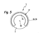
- the lid 9 is for this detachable with screws 35 or other fasteners connected to the tubular body 7. Is the display element 29 not closed in a ring shape, the receiving recess can 34 a correspondingly shortened in length have an adapted shape, as can be seen from FIG. 5.
- indicator ring 28 also between the front cover 8 and the tubular body 7 installed can be.
- the Housing 2 indicator rings 28 in a desired plurality be provided. It would also be possible to have at least one Indicator ring 28 on the front and / or rear of the housing 2 to place.
- Indicator ring 28 has an at least partially and preferably translucent in its entirety annular Indicator body 36, one colored as needed Plastic material can be used.
- Indicator body 36 are longitudinal, i.e. about the scope of the housing 2 distributed selectively, several lamps integrated, especially LEDs. They are made of the material of the Display body 36 expediently completely and capsuled.
- a suitable electrical interface 38 Via a suitable electrical interface 38, which can be designed as a plug connection device, are all illuminants 37 either directly or under Mediation of the control device 18 with the sensor device 15 or their individual sensors 16 in electrical connection.
- the illuminants receive 37 a corresponding signal that they for light output causes so that the display state of the indicator ring 28th is present.
- the display body 36 expediently has such light-guiding properties that even with a small number of lamps 37 along a lighting effect of the entire circumference occurs, as indicated in Fig. 3 is. However, it is understood that if necessary also on only light source 37 used in the form of a light strip can be spread over the entire circumferential direction of the housing 2 measured length of the display body 36 extends.
- the lamps 37 are thereby in the embodiment Display body 36 fixed and at the same time electrically with the Interface 38 connected that they on a circuit board 42nd sit with the ring-shaped design of the display element 29 preferably has an annular shape and concentric in the display body 36 is embedded.
- the interface 38 is expediently located on an axial side of the display body 36th
- the light energy could alternatively also be the indicator ring 28 can be fed via light guides.
- the Interface 38 if present, as an optical interface be carried out. With such a design could be within of the display body 36 on electrically operated lamps to be dispensed with.
- the display ring 28 becomes a pure display function have, which also enables the material of the Select annular body 36 so that the desired optical properties are present.
- a sealing function in the indicator ring 28 to integrate is the case.
- the indicator ring 28 takes over at the same time the function of an annular seal 43, the placed between the lid 9 and the tubular body 7 is the connection between these two housing components to be fluid-tight.
- the Display body 36 expediently selected a material that has sufficient sealing properties, for example an elastomeric material.
- the indicator ring 28 expediently directly via its interface 38 connected to the sensor carrier 22, within the above Connection conductor 45 an electrical connection to the electrical conductors 17 can take place, which lead to the sensors 16 to lead.
- Fig. 4 shows a different design, in which the Sensors 16 designed in particular as sliding contacts Touch contacts 46 with one or more conductor tracks 47 in Are in contact along the recess 26 extend and via the interface 38 with the lamps 37 of the indicator ring 28 are connected.
- the conductor tracks 47 can be integrated directly into the housing 2 or are located on a circuit board 48, for example is fixed to the housing and is particularly inside the Holding recess 26 is located.
- Fig. 3 makes it clear that the indicator ring is not necessarily must have an annular shape. His Shaping can in particular on the outer shape of the Orient housing 2 of drive device 1.
- the indicator ring 28 In adaptation to the square cross-sectional contour present in the exemplary embodiment of the housing 2 here has the indicator ring 28 a correspondingly polygonal one, the outline of a square following ring course. The corner areas can be rounded his.
Landscapes
- Physics & Mathematics (AREA)
- Engineering & Computer Science (AREA)
- General Physics & Mathematics (AREA)
- Optics & Photonics (AREA)
- Power Engineering (AREA)
- Fluid Mechanics (AREA)
- Mechanical Engineering (AREA)
- General Engineering & Computer Science (AREA)
- Microelectronics & Electronic Packaging (AREA)
- Illuminated Signs And Luminous Advertising (AREA)
- Vehicle Body Suspensions (AREA)
- Diaphragms For Electromechanical Transducers (AREA)
- Measuring Pulse, Heart Rate, Blood Pressure Or Blood Flow (AREA)
- Infusion, Injection, And Reservoir Apparatuses (AREA)
- Devices For Indicating Variable Information By Combining Individual Elements (AREA)
- Actuator (AREA)
Description
- Fig. 1
- die Seitenansicht einer exemplarisch dargestellten Antriebsvorrichtung, die mit einer bevorzugten Bauform der erfindungsgemäßen Anzeigeeinrichtung ausgestattet ist,
- Fig. 2
- den in Fig. 1 markierten Ausschnitt II in vergrößerter Teildarstellung und teilweise im Längsschnitt,
- Fig. 3
- die Anordnung aus Fig. 1 in einer Stirnansicht mit Blickrichtung gemäß Pfeil III,
- Fig. 4
- eine weitere Ausführungsform der Anzeigeeinrichtung in einer der Fig. 2 entsprechenden Darstellungsweise und
- Fig. 5
- eine weitere Ausführungsform der Anzeigeeinrichtung in einer der Fig. 3 entsprechenden schematischen Darstellungsweise.
Claims (22)
- Anzeigeeinrichtung zum optischen Anzeigen eines für eine Antriebsvorrichtung (1) relevanten Betriebszustandes, wobei die Antriebsvorrichtung (1) ein in einem Gehäuse (2) bewegbares Antriebsteil (4) aufweist, gekennzeichnet durch ein Anzeigeelement (29), das in einer sich entlang mindestens 180° eines Umfangs des Gehäuses (2) der Antriebsvorrichtung (1) erstreckenden Weise an dem Gehäuse (2) angeordnet oder anzuordnen ist und das in der dem Gehäuse (2) zugeordneten Gebrauchsposition während seines Anzeigezustandes über den zugeordneten Gehäuseumfang verteilt Licht aussendet.
- Anzeigeeinrichtung nach Anspruch 1, dadurch gekennzeichnet, daß der anzuzeigende Betriebszustand der Schaltzustand einer Sensoreinrichtung (15) der Antriebsvorrichtung (1) ist.
- Anzeigeeinrichtung nach Anspruch 1 oder 2, dadurch gekennzeichnet, daß es sich bei der Antriebsvorrichtung (1) um einen elektrisch und/oder fluidisch betätigten Linearantrieb handelt, beispielsweise um einen fluidbetätigten Arbeitszylinder.
- Anzeigeeinrichtung nach einem der Ansprüche 1 bis 3, dadurch gekennzeichnet, daß das Anzeigeelement (29) im am Gehäuse der Antriebsvorrichtung (1) angeordneten Zustand koaxial zu diesem Gehäuse (2) plaziert ist.
- Anzeigeeinrichtung nach einem der Ansprüche 1 bis 4, dadurch gekennzeichnet, daß das Anzeigeelement (29) in einer nach radial außen hin offenen Aufnahmevertiefung (34) des Gehäuses (2) angeordnet ist.
- Anzeigeeinrichtung nach Anspruch 5, dadurch gekennzeichnet, daß die Aufnahmevertiefung (34) von einem zwischen zwei Bestandteilen (7, 9) des Gehäuses (2) definierten Zwischenraum gebildet ist.
- Anzeigeeinrichtung nach Anspruch 6, dadurch gekennzeichnet, daß es sich bei den beiden Bestandteilen um einen rohrförmigen Körper (7) und einen daran angebrachten Deckel (9) des Gehäuses (2) handelt.
- Anzeigeeinrichtung nach einem der Ansprüche 1 bis 7, dadurch gekennzeichnet, daß das Anzeigeelement (29) einen zumindest partiell lichtdurchlässige und/oder lichtleitende Eigenschaften aufweisenden Anzeigekörper (36) enthält, der mit mindestens einem Leuchtmittel (37), insbesondere eine Leuchtdiode, versehen ist.
- Anzeigeeinrichtung nach Anspruch 8, dadurch gekennzeichnet, daß das mindestens eine Leuchtmittel (37) in den Anzeigekörper (36) eingebettet ist.
- Anzeigeeinrichtung nach Anspruch 8 oder 9, dadurch gekennzeichnet, daß der Anzeigekörper (36) entlang seiner gesamten Länge lichtdurchlässig und/oder lichtleitend ausgebildet ist.
- Anzeigeeinrichtung nach einem der Ansprüche 8 bis 10, gekennzeichnet durch eine Mehrzahl über die Länge des Anzeigekörpers (36) verteilt angeordnete Leuchtmittel (37).
- Anzeigeeinrichtung nach einem der Ansprüche 8 bis 11, dadurch gekennzeichnet, daß das mindestens eine Leuchtmittel (37) an einer dem Anzeigekörper (36) zugeordneten Leiterplatte (42) vorgesehen ist.
- Anzeigeeinrichtung nach einem der Ansprüche 8 bis 12, dadurch gekennzeichnet, daß der Anzeigekörper (36) aus Kunststoffmaterial besteht und dabei vorzugsweise aus Material mit Dichteigenschaften.
- Anzeigeeinrichtung nach einem der Ansprüche 1 bis 13, dadurch gekennzeichnet, daß das Anzeigeelement (29) eine zwischen zwei Bestandteilen (7, 9) des Gehäuses (2) wirkende Dichtung (43) bildet.
- Anzeigeeinrichtung nach einem der Ansprüche 1 bis 14, dadurch gekennzeichnet, daß das Anzeigeelement (29) eine Schnittstelle (38) zur Einspeisung des die Lichtausgabe hervorrufenden Signals aufweist.
- Anzeigeeinrichtung nach einem der Ansprüche 1 bis 15, dadurch gekennzeichnet, daß das Anzeigeelement (29) mit einer der Antriebsvorrichtung (1) zugeordneten Sensoreinrichtung (18) gekoppelt ist, insbesondere mit einer zur Erfassung mindestens einer Position des Antriebsteils (4) dienenden Sensoreinrichtung (15).
- Anzeigeeinrichtung nach einem der Ansprüche 1 bis 16, dadurch gekennzeichnet, daß das Anzeigeelement (29) derart gestaltet ist, daß seine radiale Außenfläche etwa bündig mit den benachbarten Außenflächen des Gehäuses (2) verläuft.
- Anzeigeeinrichtung nach einem der Ansprüche 1 bis 17, dadurch gekennzeichnet, daß das Anzeigeelement (29) als sich in Gebrauchsposition über vorzugsweise den gesamten Umfang des Gehäuses (2) der Antriebsvorrichtung (1) erstreckender Anzeigering (28) ausgeführt ist.
- Anzeigeeinrichtung nach Anspruch 18 in Verbindung mit Anspruch 5 oder 6, dadurch gekennzeichnet, daß der Anzeigering (28) in einer ringförmigen Aufnahmevertiefung (34) des Gehäuses (2) angeordnet ist.
- Anzeigeeinrichtung nach Anspruch 18 oder 19 in Verbindung mit Anspruch 12, dadurch gekennzeichnet, daß die Leiterplatte (42) ringförmig ausgebildet und konzentrisch zu dem ebenfalls ringförmigen Anzeigekörper (36) angeordnet ist.
- Anzeigeeinrichtung nach einem der Ansprüche 18 bis 20, dadurch gekennzeichnet, daß das Anzeigeelement (29) kreisringförmig ausgebildet ist.
- Anzeigeeinrichtung nach einem der Ansprüche 18 bis 20, dadurch gekennzeichnet, daß das Anzeigeelement (29) einen mehreckförmigen und beispielsweise quadratischen Ringverlauf hat.
Applications Claiming Priority (3)
| Application Number | Priority Date | Filing Date | Title |
|---|---|---|---|
| DE19921474 | 1999-05-08 | ||
| DE19921474A DE19921474A1 (de) | 1999-05-08 | 1999-05-08 | Anzeigeeinrichtung |
| PCT/EP2000/002679 WO2000068579A1 (de) | 1999-05-08 | 2000-03-27 | Anzeigeeinrichtung |
Publications (2)
| Publication Number | Publication Date |
|---|---|
| EP1093546A1 EP1093546A1 (de) | 2001-04-25 |
| EP1093546B1 true EP1093546B1 (de) | 2004-05-12 |
Family
ID=7907564
Family Applications (1)
| Application Number | Title | Priority Date | Filing Date |
|---|---|---|---|
| EP00926760A Expired - Lifetime EP1093546B1 (de) | 1999-05-08 | 2000-03-27 | Anzeigeeinrichtung |
Country Status (7)
| Country | Link |
|---|---|
| US (1) | US6427576B1 (de) |
| EP (1) | EP1093546B1 (de) |
| JP (1) | JP2002544445A (de) |
| AT (1) | ATE266816T1 (de) |
| DE (2) | DE19921474A1 (de) |
| DK (1) | DK1093546T3 (de) |
| WO (1) | WO2000068579A1 (de) |
Families Citing this family (18)
| Publication number | Priority date | Publication date | Assignee | Title |
|---|---|---|---|---|
| US6736611B2 (en) * | 2000-10-23 | 2004-05-18 | Goodrich Corporation | Aircraft fluid delivery device |
| SE522652C2 (sv) * | 2001-07-06 | 2004-02-24 | Parker Hannifin Ab | Kolv- cylinderanordning med minst en lägessensor |
| SE517799C2 (sv) | 2001-08-15 | 2002-07-16 | Mecman Ab Rexroth | Tryckfluidcylinder jämte indikeringsanordning därför |
| USD480405S1 (en) | 2002-02-02 | 2003-10-07 | Festo Ag & Co. | Working cylinder |
| ES2223988T3 (es) | 2002-04-05 | 2005-03-01 | FESTO AG & CO | Dispositivo de accionamiento accionado por liquido. |
| SE525936C2 (sv) * | 2003-04-07 | 2005-05-31 | Parker Hannifin Ab | Kolv- cylinderanordning med positionskännande organ |
| DE102005025670A1 (de) * | 2005-06-03 | 2006-12-07 | Siemens Ag | Elektronisches Gerät |
| DE502007002952D1 (de) * | 2007-08-29 | 2010-04-08 | Festo Ag & Co Kg | Elektrische Linearantriebsvorrichtung |
| DE102009007657A1 (de) * | 2009-02-05 | 2010-08-12 | Wabco Gmbh | Kolben-Zylinderanordnung mit integrierter Messeinrichtung |
| US8157500B1 (en) * | 2009-08-04 | 2012-04-17 | Husmann Shawn M | Forklift tilt direction indicator |
| NO2588709T3 (de) * | 2010-07-01 | 2018-07-21 | ||
| US9428994B2 (en) | 2010-07-01 | 2016-08-30 | National Oilwell Varco, L.P. | Blowout preventer monitor with trigger sensor and method of using same |
| USD682901S1 (en) * | 2012-04-02 | 2013-05-21 | Festo Ag & Co. Kg | Pneumatic cylinder |
| US9970569B2 (en) * | 2015-12-17 | 2018-05-15 | Cameron International Corporation | Closure member position indicator system for use in a blowout preventer |
| US9822603B2 (en) * | 2015-12-30 | 2017-11-21 | Cameron International Corporation | Subsea equipment visual indicator |
| JP6437036B2 (ja) * | 2017-03-30 | 2018-12-12 | 本田技研工業株式会社 | アクチュエータの設定方法及び流体圧制御回路 |
| DE102017208317A1 (de) * | 2017-05-17 | 2018-11-22 | Festo Ag & Co. Kg | Sensoreinrichtung und System |
| US10745994B2 (en) * | 2018-04-24 | 2020-08-18 | Ge Oil & Gas Pressure Control Lp | System and method for preventing inadvertent valve closures |
Family Cites Families (4)
| Publication number | Priority date | Publication date | Assignee | Title |
|---|---|---|---|---|
| IT8653062V0 (it) * | 1986-03-03 | 1986-03-03 | Siette Spa | Ghiera luminosa per accessori di bordo di veicoli |
| JP2592521B2 (ja) * | 1989-03-22 | 1997-03-19 | 株式会社コガネイ | アクチュエータ用位置検出装置 |
| DE8909155U1 (de) * | 1989-07-28 | 1989-11-02 | H. Kuhnke Gmbh Kg, 23714 Malente | Sensor |
| CH691003A5 (fr) * | 1996-08-13 | 2001-03-30 | Parker Lucifer Sa | Tête de commande électro-pneumatique pour actuateurs. |
-
1999
- 1999-05-08 DE DE19921474A patent/DE19921474A1/de not_active Withdrawn
-
2000
- 2000-03-27 DE DE50006390T patent/DE50006390D1/de not_active Expired - Lifetime
- 2000-03-27 AT AT00926760T patent/ATE266816T1/de not_active IP Right Cessation
- 2000-03-27 EP EP00926760A patent/EP1093546B1/de not_active Expired - Lifetime
- 2000-03-27 JP JP2000617334A patent/JP2002544445A/ja active Pending
- 2000-03-27 WO PCT/EP2000/002679 patent/WO2000068579A1/de not_active Ceased
- 2000-03-27 US US09/719,765 patent/US6427576B1/en not_active Expired - Fee Related
- 2000-03-27 DK DK00926760T patent/DK1093546T3/da active
Also Published As
| Publication number | Publication date |
|---|---|
| ATE266816T1 (de) | 2004-05-15 |
| DK1093546T3 (da) | 2004-06-28 |
| EP1093546A1 (de) | 2001-04-25 |
| DE50006390D1 (de) | 2004-06-17 |
| JP2002544445A (ja) | 2002-12-24 |
| US6427576B1 (en) | 2002-08-06 |
| DE19921474A1 (de) | 2001-01-18 |
| WO2000068579A1 (de) | 2000-11-16 |
Similar Documents
| Publication | Publication Date | Title |
|---|---|---|
| EP1093546A1 (de) | Anzeigeeinrichtung | |
| EP2282250B1 (de) | Daumenrad | |
| EP2366926B1 (de) | Vorrichtung zur Endlagenerkennung in Hubventilen, Ventilbausatz sowie Sensormodul hierfür | |
| EP2182341B1 (de) | Elektrische Einrichtung zur Verschleißerkennung elastomerer dynamischer Dichtungen | |
| DE102010023888B4 (de) | Druckschalter | |
| DE3507167C2 (de) | ||
| EP2407852A1 (de) | Haltevorrichtung für eine Bedieneinrichtung | |
| EP2994927B1 (de) | Kippschalter für mehrere schaltstellungen | |
| EP1391615B1 (de) | Kolben-Zylindereinheit | |
| DE102007014264A1 (de) | Leucht-Schaltstellungsanzeige | |
| DE102009020286A1 (de) | Kolben mit variablem Permanent-Magneten | |
| EP0775835B1 (de) | Positionserfassungsvorrichtung | |
| EP1533451B1 (de) | Baueinheit bestehend aus einer Handhabe und wenigstens einer Funktionseinheit | |
| EP1309803B1 (de) | Linearantrieb | |
| EP2064451B1 (de) | Fluidtechnisches gerät mit lichtleiter | |
| EP0676550B1 (de) | Arbeitszylinder | |
| EP0417048A2 (de) | Elektrische Schaltvorrichtung mit Leuchtmitteln | |
| DE10225016B4 (de) | Beleuchtbare Betätigungsknopfanordnung | |
| EP0591614B1 (de) | Kolben-Zylinder-Aggregat | |
| DE3901289A1 (de) | Beleuchtetes bedienungselement | |
| DE102005060674B4 (de) | Positionssensor in Stabbauweise sowie Verfahren zum Austausch | |
| DE102004012869B4 (de) | Elektrischer Schalter mit integrierter Leucht-Funktionsanzeige | |
| DE102013015973A1 (de) | Steuerventilanordnung | |
| EP2746593A1 (de) | Ventilanordnung | |
| EP0903558A1 (de) | Anordnung eines Näherungssensors an einer Kolben-Zylinder Einheit |
Legal Events
| Date | Code | Title | Description |
|---|---|---|---|
| PUAI | Public reference made under article 153(3) epc to a published international application that has entered the european phase |
Free format text: ORIGINAL CODE: 0009012 |
|
| 17P | Request for examination filed |
Effective date: 20001121 |
|
| AK | Designated contracting states |
Kind code of ref document: A1 Designated state(s): AT BE CH CY DE DK ES FI FR GB GR IE IT LI LU MC NL PT SE |
|
| GRAP | Despatch of communication of intention to grant a patent |
Free format text: ORIGINAL CODE: EPIDOSNIGR1 |
|
| GRAS | Grant fee paid |
Free format text: ORIGINAL CODE: EPIDOSNIGR3 |
|
| GRAA | (expected) grant |
Free format text: ORIGINAL CODE: 0009210 |
|
| AK | Designated contracting states |
Kind code of ref document: B1 Designated state(s): AT BE CH CY DE DK ES FI FR GB GR IE IT LI LU MC NL PT SE |
|
| PG25 | Lapsed in a contracting state [announced via postgrant information from national office to epo] |
Ref country code: IE Free format text: LAPSE BECAUSE OF FAILURE TO SUBMIT A TRANSLATION OF THE DESCRIPTION OR TO PAY THE FEE WITHIN THE PRESCRIBED TIME-LIMIT Effective date: 20040512 |
|
| REG | Reference to a national code |
Ref country code: GB Ref legal event code: FG4D Free format text: NOT ENGLISH |
|
| REG | Reference to a national code |
Ref country code: CH Ref legal event code: EP |
|
| REG | Reference to a national code |
Ref country code: IE Ref legal event code: FG4D Free format text: GERMAN |
|
| REF | Corresponds to: |
Ref document number: 50006390 Country of ref document: DE Date of ref document: 20040617 Kind code of ref document: P |
|
| REG | Reference to a national code |
Ref country code: DK Ref legal event code: T3 |
|
| PG25 | Lapsed in a contracting state [announced via postgrant information from national office to epo] |
Ref country code: SE Free format text: LAPSE BECAUSE OF FAILURE TO SUBMIT A TRANSLATION OF THE DESCRIPTION OR TO PAY THE FEE WITHIN THE PRESCRIBED TIME-LIMIT Effective date: 20040812 Ref country code: GR Free format text: LAPSE BECAUSE OF FAILURE TO SUBMIT A TRANSLATION OF THE DESCRIPTION OR TO PAY THE FEE WITHIN THE PRESCRIBED TIME-LIMIT Effective date: 20040812 |
|
| PG25 | Lapsed in a contracting state [announced via postgrant information from national office to epo] |
Ref country code: ES Free format text: LAPSE BECAUSE OF FAILURE TO SUBMIT A TRANSLATION OF THE DESCRIPTION OR TO PAY THE FEE WITHIN THE PRESCRIBED TIME-LIMIT Effective date: 20040823 |
|
| GBT | Gb: translation of ep patent filed (gb section 77(6)(a)/1977) | ||
| REG | Reference to a national code |
Ref country code: IE Ref legal event code: FD4D |
|
| ET | Fr: translation filed | ||
| PLBE | No opposition filed within time limit |
Free format text: ORIGINAL CODE: 0009261 |
|
| STAA | Information on the status of an ep patent application or granted ep patent |
Free format text: STATUS: NO OPPOSITION FILED WITHIN TIME LIMIT |
|
| PG25 | Lapsed in a contracting state [announced via postgrant information from national office to epo] |
Ref country code: AT Free format text: LAPSE BECAUSE OF NON-PAYMENT OF DUE FEES Effective date: 20050327 Ref country code: LU Free format text: LAPSE BECAUSE OF NON-PAYMENT OF DUE FEES Effective date: 20050327 Ref country code: CY Free format text: LAPSE BECAUSE OF FAILURE TO SUBMIT A TRANSLATION OF THE DESCRIPTION OR TO PAY THE FEE WITHIN THE PRESCRIBED TIME-LIMIT Effective date: 20050327 |
|
| PG25 | Lapsed in a contracting state [announced via postgrant information from national office to epo] |
Ref country code: BE Free format text: LAPSE BECAUSE OF NON-PAYMENT OF DUE FEES Effective date: 20050331 Ref country code: MC Free format text: LAPSE BECAUSE OF NON-PAYMENT OF DUE FEES Effective date: 20050331 Ref country code: LI Free format text: LAPSE BECAUSE OF NON-PAYMENT OF DUE FEES Effective date: 20050331 Ref country code: CH Free format text: LAPSE BECAUSE OF NON-PAYMENT OF DUE FEES Effective date: 20050331 |
|
| 26N | No opposition filed |
Effective date: 20050215 |
|
| BERE | Be: lapsed |
Owner name: *FESTO A.G. & CO. Effective date: 20050331 |
|
| PG25 | Lapsed in a contracting state [announced via postgrant information from national office to epo] |
Ref country code: NL Free format text: LAPSE BECAUSE OF NON-PAYMENT OF DUE FEES Effective date: 20051001 |
|
| REG | Reference to a national code |
Ref country code: CH Ref legal event code: PL |
|
| NLV4 | Nl: lapsed or anulled due to non-payment of the annual fee |
Effective date: 20051001 |
|
| PGFP | Annual fee paid to national office [announced via postgrant information from national office to epo] |
Ref country code: FI Payment date: 20070212 Year of fee payment: 8 |
|
| BERE | Be: lapsed |
Owner name: *FESTO A.G. & CO. Effective date: 20050331 |
|
| PG25 | Lapsed in a contracting state [announced via postgrant information from national office to epo] |
Ref country code: PT Free format text: LAPSE BECAUSE OF NON-PAYMENT OF DUE FEES Effective date: 20041012 |
|
| PGFP | Annual fee paid to national office [announced via postgrant information from national office to epo] |
Ref country code: GB Payment date: 20080228 Year of fee payment: 9 Ref country code: IT Payment date: 20080327 Year of fee payment: 9 |
|
| PGFP | Annual fee paid to national office [announced via postgrant information from national office to epo] |
Ref country code: FR Payment date: 20080314 Year of fee payment: 9 |
|
| PG25 | Lapsed in a contracting state [announced via postgrant information from national office to epo] |
Ref country code: FI Free format text: LAPSE BECAUSE OF NON-PAYMENT OF DUE FEES Effective date: 20080327 |
|
| PGFP | Annual fee paid to national office [announced via postgrant information from national office to epo] |
Ref country code: DK Payment date: 20090313 Year of fee payment: 10 |
|
| GBPC | Gb: european patent ceased through non-payment of renewal fee |
Effective date: 20090327 |
|
| REG | Reference to a national code |
Ref country code: FR Ref legal event code: ST Effective date: 20091130 |
|
| PG25 | Lapsed in a contracting state [announced via postgrant information from national office to epo] |
Ref country code: FR Free format text: LAPSE BECAUSE OF NON-PAYMENT OF DUE FEES Effective date: 20091123 Ref country code: GB Free format text: LAPSE BECAUSE OF NON-PAYMENT OF DUE FEES Effective date: 20090327 |
|
| REG | Reference to a national code |
Ref country code: DK Ref legal event code: EBP |
|
| PG25 | Lapsed in a contracting state [announced via postgrant information from national office to epo] |
Ref country code: IT Free format text: LAPSE BECAUSE OF NON-PAYMENT OF DUE FEES Effective date: 20090327 |
|
| PG25 | Lapsed in a contracting state [announced via postgrant information from national office to epo] |
Ref country code: DK Free format text: LAPSE BECAUSE OF NON-PAYMENT OF DUE FEES Effective date: 20100331 |
|
| PGFP | Annual fee paid to national office [announced via postgrant information from national office to epo] |
Ref country code: DE Payment date: 20170223 Year of fee payment: 18 |
|
| REG | Reference to a national code |
Ref country code: DE Ref legal event code: R119 Ref document number: 50006390 Country of ref document: DE |
|
| PG25 | Lapsed in a contracting state [announced via postgrant information from national office to epo] |
Ref country code: DE Free format text: LAPSE BECAUSE OF NON-PAYMENT OF DUE FEES Effective date: 20181002 |