EP1093234A1 - Verfahren und Anordnung zur Verminderung der Belastung eines Mobiltelefon-Benutzers durch elektromagnetische Strahlung im Funkwellenbereich - Google Patents
Verfahren und Anordnung zur Verminderung der Belastung eines Mobiltelefon-Benutzers durch elektromagnetische Strahlung im Funkwellenbereich Download PDFInfo
- Publication number
- EP1093234A1 EP1093234A1 EP00118561A EP00118561A EP1093234A1 EP 1093234 A1 EP1093234 A1 EP 1093234A1 EP 00118561 A EP00118561 A EP 00118561A EP 00118561 A EP00118561 A EP 00118561A EP 1093234 A1 EP1093234 A1 EP 1093234A1
- Authority
- EP
- European Patent Office
- Prior art keywords
- infrared
- radio
- radio wave
- mobile phone
- converter
- Prior art date
- Legal status (The legal status is an assumption and is not a legal conclusion. Google has not performed a legal analysis and makes no representation as to the accuracy of the status listed.)
- Granted
Links
- 238000000034 method Methods 0.000 title claims description 7
- 230000005540 biological transmission Effects 0.000 claims description 20
- 230000005670 electromagnetic radiation Effects 0.000 claims description 18
- 230000005855 radiation Effects 0.000 claims description 8
- 230000002457 bidirectional effect Effects 0.000 claims description 2
- 230000008054 signal transmission Effects 0.000 claims 1
- 238000006243 chemical reaction Methods 0.000 description 3
- 239000000463 material Substances 0.000 description 3
- 230000001681 protective effect Effects 0.000 description 3
- 238000010586 diagram Methods 0.000 description 2
- 206010073306 Exposure to radiation Diseases 0.000 description 1
- 206010016275 Fear Diseases 0.000 description 1
- 230000003750 conditioning effect Effects 0.000 description 1
- 230000006735 deficit Effects 0.000 description 1
- 230000008021 deposition Effects 0.000 description 1
- 239000013307 optical fiber Substances 0.000 description 1
- 230000000717 retained effect Effects 0.000 description 1
- 230000003068 static effect Effects 0.000 description 1
Images

Classifications
-
- H—ELECTRICITY
- H04—ELECTRIC COMMUNICATION TECHNIQUE
- H04B—TRANSMISSION
- H04B1/00—Details of transmission systems, not covered by a single one of groups H04B3/00 - H04B13/00; Details of transmission systems not characterised by the medium used for transmission
- H04B1/38—Transceivers, i.e. devices in which transmitter and receiver form a structural unit and in which at least one part is used for functions of transmitting and receiving
- H04B1/3827—Portable transceivers
- H04B1/3833—Hand-held transceivers
- H04B1/3838—Arrangements for reducing RF exposure to the user, e.g. by changing the shape of the transceiver while in use
Definitions
- the invention relates to a method and an arrangement for reduction the exposure of a mobile phone user in a lounge area, in particular a vehicle interior or a building interior, due to electromagnetic radiation in the radio wave range.
- Cordless cell phones so-called cell phones, are currently becoming available increasingly used.
- Voice information and other data not over lines, the landline phone in the form of electrical Transmit signals, but as a radio signal, which from a Transceiver of the mobile phone is generated or received.
- Radio signal over distances of a few kilometers to one
- To be able to transmit transfer station are correspondingly high Transmitting powers of up to a few watts are necessary.
- Part of this Transmission power is considered in the user's head when operating the mobile phone Heat is absorbed because the cell phone's antenna extends in all directions emits about the same intensity and is regularly in use in the immediate vicinity of the head. Whether and what physical damage this energy deposition can cause is currently not clear. Indeed one strives to keep the energy load as low as possible.
- the invention is intended to be such Mobile phone users from increased exposure to radiation Protect electromagnetic waves in the radio wave range.
- infrared converter the wired electrical signals via infrared interfaces implement and emit as infrared signals and infrared receivers are available wirelessly over a certain distance known, for example on storage racks.
- the invention has for its object a method and an arrangement to reduce the burden on a mobile phone user electromagnetic radiation in the radio wave range is available too the user in a defined area, e.g. a vehicle or a building interior.
- the solution to this problem is characterized in that electromagnetic radiation emitted by the mobile phone in the Radio wave range by means of a first radio wave infrared converter in electromagnetic radiation implemented in the infrared range and otherwise is shielded, and that by the first radio wave infrared converter infrared radiation emitted by means of a second radio-wave infrared converter, which is located at the edge of the lounge area, in electromagnetic radiation in the radio wave range is implemented.
- the first radio wave-infrared converter is small in space Distance to the mobile phone arranged.
- the solution to the problem is characterized by a first radio wave infrared converter, which is in close proximity to the Mobile phone is arranged and transmitted by the transmitter of the mobile phone to receive electromagnetic radiation in the radio wave range (radio signals) and is able to convert into infrared signals, one Shielding device which can be placed on the mobile phone and Is able to shield radio signals from the mobile phone user, and a second radio wave infrared converter, which on the edge of the Stay area is arranged and the first radio wave-infrared converter transmitted infrared signals received and in radio signals is able to implement. It is the first radio wave to infrared converter and / or the shielding device can be connected to the mobile phone in such a way, that infrared signals to the second radio wave infrared converter are transferable.
- electromagnetic radiation in Radio wave range in close proximity to the user's head almost completely shielded.
- the data transmission in this spatial area is instead via an infrared transmission path with an infrared signal made, which is harmless to the user.
- the Immediate implementation of the radio signal emitted by the mobile phone spatial proximity to it in an infrared signal also has the advantage that on an increased transmission power can be dispensed with, since there are only small distances must be overcome.
- the distance between the antenna of the Mobile phones or their transmitters and the receiver of the radio wave infrared converter can be very small on the order of millimeters Centimeters can be selected. This makes it possible to use the mobile phone too to operate with reduced transmission power, which additionally the Life of its battery or accumulator is extended. This reduced transmission power is also easier for the user be shielded; less shielding material is required.
- the transmission of the radio signal from the second converter has too an external conversion station has the advantage that, on the one hand, the transmission power this converter can be screened or directed and on the other hand, a considerable reduction in the transmission power of the user is already exposed due to the spatial distance from the first and second converter is achieved.
- the shielding is carried out by means of a shielding device, which is preferably placed on the mobile phone and this whole or encloses in the area of the antenna.
- Shielding device from a protective covering of the mobile phone, in the Wall of the first radio wave-infrared converter is arranged.
- This contains at least one receiver for radio signals, one transmitter for Infrared signals and circuits for converting radio waves into infrared waves, preferably also transmitters for radio and receivers for Infrared signals.
- Infrared transmitter and receiver of the first converter arranged so that this send infrared signals to the outside or from can receive such outside.
- Radio wave transmitter and receiver of the first are in the interior of the shielding device directed. In this way, preferably no radio signals penetrate from Mobile phone to the outside. Instead, the radio signal is converted into an infrared signal implemented, the information content of the signal is retained.
- the infrared waves are in the lounge area in a direct line over the Air or a transmission medium that is transparent for this wavelength second radio wave infrared converter. It is also conceivable an optical fiber cable.
- the second converter contains a receiver for Infrared waves and a transmitter for radio signals.
- the transmitter for Radio signals mainly radiate in the area outside the Area from. For a vehicle or a closed one
- the antenna belonging to this transmitter is outside the building of the enclosed space that forms the lounge area. At the vehicle antenna can be shared with a vehicle.
- the transmitter of the second radio wave infrared converter is partially to the lounge area, this is harmless, since the Radiation intensity disproportionately with increasing distance falls off. Even at a distance of only half a meter to one manages to get the radiation that the user is exposed to To reduce many times.
- the great advantage of the invention is, however, that the second radio wave transmitter is spaced from the user and its position can be chosen so that a shield is achieved by intermediate material.
- the second radio wave-infrared converter existing infrared transmission path, preferably bidirectional operated.
- both radio wave infrared converters each have transmit and Receiving devices for radio and infrared signals.
- Received signal is then from the second radio wave infrared converter received, converted into an infrared signal, to the first radio wave-infrared converter transmitted and converted back into a radio signal there, which is received by the mobile phone in the usual way.
- FIG. 1 shows a basic illustration of a radio wave infrared converter 32 as part of an arrangement according to the invention (first or second radio wave infrared converter).
- the converter 32 has a transmission and Receiving antenna 12 for radio waves.
- a radio signal is sent from the Antenna 12 received and 11 via a transmitting and receiving switch Radio receiver 1 forwarded.
- the signal processing and control unit 2 the demodulated signal is processed and the call control carried out.
- the output signals of the unit 2 are the modulator 3 fed a implementation on frequencies of the infrared range makes.
- the signal is amplified in driver 4 and sent to the infrared transmitter diode 5 given. With the signals, the IR transmitter diode 5 becomes Emits infrared signals which are the same Contain information such as the radio signal. In this way it succeeds Conversion of incoming radio signals into infrared signals (reception path).
- an infrared receiving diode 6 is provided to implement the other signal direction, i.e. to implement outgoing infrared signals in radio signals (transmission path).
- Received IR signals are given by the receiving diode 6 to the IR demodulator 7.
- Whose Output signals are in a signal processing and control unit 8, which also with the corresponding signal processing and control unit 2 can match in the reception path, brought to the standardized values.
- the control of send and receive status executed.
- the switch 11 serves that signals to be emitted are not in get the receiver 1, but to the antenna 12.
- the decoupling of sent and received IR signals is from the Signal conditioning units 2 and 8 controlled. Additional components such as Power supplies are not shown.
- FIG. 2 shows a shielding device 15 placed on a mobile telephone 13 with radio wave infrared converter 16 as a mobile part of the invention Arrangement.
- the shielding device 15 consists of a cap that on the Mobile phone 13 is placed and also covers its antenna 14. A closed is between the mobile phone 13 and the shielding device 15 Cavity 17 formed.
- the shielding device 15 consists of a Material that emits strong electromagnetic radiation in the radio wave range attenuates so that the radio radiation emitted by the antenna 14 Cavity 17 does not leave.
- a radio wave infrared converter 16 e.g. according to Figure 1, arranged for two channel conversion of radio signals into infrared signals and vice versa.
- An infrared signal coming from outside is transmitted by means of a externally arranged IR receive diode 18 received and in an inward radiated radio signal implemented in the cavity 17. This is about the antenna 14 received and can by the mobile phone processed, e.g. be output as a speech signal.
- FIG. 3 shows a basic illustration of a statonary radio wave infrared converter 33 as a stationary element of an arrangement according to the invention.
- the converter 33 has an interface 20 for transmission or for Receive infrared signals, which are an infrared transmitter diode and Infrared receiver diode includes. Furthermore, as an interface to An antenna 22 is available for transmitting or receiving radio signals.
- the interface 20 and the antenna 22 are via converter circuits 21, e.g. according to Figure 1, so that each other radio signals in Infrared signals with essentially the same information content implemented and vice versa.
- the interface 20 and the antenna 22 are spatial so arranged that the antenna transmits and receives Radio signals do not get into the spatial area in which the IR signals be sent and received. This is through a shield here shown for radio signals 23 between interface 20 and antenna 22.
- the antenna 22 is outside and the IR transmit and Receiving diodes arranged within the room, the radio wave free to be held.
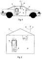
- the arrangement according to the invention consists of a mobile part 24, namely a shielding device which can be placed on a mobile telephone 25 and has a Radio wave infrared converter according to FIG. 2, and a stationary part 26.
- the stationary part 26 consists of an antenna 27 for generation and Receiving radio signals and an infrared interface 28 for generation and for receiving infrared signals according to Figure 3.
- Radio waves generated by the mobile phone 25 are shielded by means of the mobile part 25 and converted into infrared signals implemented.
- the radio signal sources from the interior 29 of the Vehicle 30 or the building 31 can be moved to the outside, the Radio wave exposure of the location area of a mobile phone user be reduced.
- the device according to the invention can be used as an accessory to commercially available devices Advantageously use mobile phones commercially.
Landscapes
- Engineering & Computer Science (AREA)
- Computer Networks & Wireless Communication (AREA)
- Signal Processing (AREA)
- Mobile Radio Communication Systems (AREA)
- Telephone Set Structure (AREA)
- Optical Communication System (AREA)
Abstract
Description
- Figur 1
- eine Prinzipdarstellung eines Funkwellen-Infrarotumsetzers
- Figur 2
- eine auf ein Mobiltelefon aufgesetzte Abschirmvorrichtung mit Funkwellen-Infrarotumsetzer
- Figur 3
- eine Prinzipdarstellung eines statonären Funkwellen-Infrarotumsetzers
- Figur 4
- eine erfindungsgemäße Anordnung zur Verminderung der Funkwellen-Abstrahlung innerhalb eines Automobil-Innenraums
- Figur 5
- eine erfindungsgemäße Anordnung zur Verminderung der Funkwellen-Abstrahlung innerhalb eines Hauses
Claims (8)
- Verfahren zur Verminderung der Belastung eines Mobiltelefon-Benutzers in einem Aufenthaltsbereich (29), insbesondere einem Fahrzeug-Innenraum oder einem Gebäude-Innenraum, durch elektromagnetische Strahlung im Funkwellenbereich,
dadurch gekennzeichnet,
daß vom Mobiltelefon (13, 25) ausgesendete elektromagnetische Strahlung im Funkwellenbereich mittels eines ersten Funkwellen-Infrarot-Umsetzers (16, 24) in elektromagnetische Strahlung im Infrarotbereich umgesetzt und ansonsten abgeschirmt wird,
und daß die von ersten Funkwellen-Infrarot-Umsetzer (16, 24) ausgesendete Infrarot-Strahlung mittels eines zweiten Funkwellen-Infrarot-Umsetzers (26), der am Rand des Aufenthaltsbereichs (29) angeordnet ist, in elektromagnetische Strahlung im Funkwellenbereich umgesetzt wird. - Verfahren nach Anspruch 1,
dadurch gekennzeichnet,
daß die vom zweiten Funkwellen-Infrarot-Umsetzer (26) ausgesendete Strahlung im Funkwellenbereich zum Aufenthaltsbereich (29) hin abgeschirmt wird. - Verfahren nach Anspruch 1 oder 2,
dadurch gekennzeichnet,
daß sich das vom Mobiltelefon (13, 25) und vom zweiten Funkwellen-Infrarot-Umsetzer (26) erzeugte Funksignal hinsichtlich ihres Informationsgehalts entsprechen. - Verfahren nach Anspruch 1, 2 oder 3,
dadurch gekennzeichnet,
daß von einer Sendestation ausgesendete elektromagnetische Strahlung im Funkwellenbereich mittels des zweiten Funkwellen-Infrarot-Umsetzers (26) in elektromagnetische Strahlung im Infrarotbereich umgesetzt, zum Mobiltelefon (13, 25) übertragen und dort mittels des ersten Funkwellen-Infrarot-Umsetzers (16, 24) in elektromagnetische Strahlung im Funkwellenbereich umgesetzt wird, welche vom Empfänger (14) des Mobiltelefons empfangen und ansonsten abgeschirmt wird. - Anordnung zur Verminderung der Belastung eines Mobiltelefon-Benutzers in einem Aufenthaltsbereich (29), insbesondere einem Fahrzeug-Innenraum oder einem Gebäude-Innenraum, durch vom Sender (14) eines Mobiltelefons (13, 25) ausgesendete elektromagnetische Strahlung im Funkwellenbereich, gekennzeichnet durch
einen ersten Funkwellen-Infrarot-Umsetzer (16, 24), der in räumlicher Nähe zum Mobiltelefon angeordnet ist und vom Sender des Mobiltelefons ausgesendete elektromagnetische Strahlung im Funkwellenbereich (Funksignale) zu empfangen und in Infrarot-Signale umzusetzen imstande ist,
eine Abschirmeinrichtung (15), welche auf das Mobiltelefon aufsetzbar ist und Funksignale vom Mobiltelefon-Benutzer abzuschirmen imstande ist, einen zweiten Funkwellen-Infrarot-Umsetzer (26), welcher am Rand des Aufenthaltsbereichs angeordnet ist und vom ersten Funkwellen-Infrarot-Umsetzer (16, 24) übertragene Infrarot-Signale zu empfangen und in Funksignale umzusetzen imstande ist,
wobei der erste Funkwellen-Infrarot-Umsetzer (16, 24) und/oder die Abschirmeinrichtung (15) derart mit dem Mobiltelefon verbindbar sind, daß Infrarot-Signale zum zweiten Funkwellen-Infrarot-Umsetzer (26) übertragbar sind. - Anordnung nach Anspruch 5,
dadurch gekennzeichnet,
daß die Infrarot-Übertragungsstrecke, die aus dem ersten und dem zweiten Funkwellen-Infrarot-Umsetzer gebildet ist, zur bidirektionalen Signalübertragung ausgelegt ist. - Anordnung nach Anspruch 5 oder 6,
dadurch gekennzeichnet,
daß der Aufenthaltsbereich (29) der Innenraum eines Fahrzeugs (30) ist und der zweite Funkwellen-Infrarot-Umsetzer eine Sende- und Empfangseinrichtung für Funksignale mit einer Antenne (27) aufweist, wobei die Antenne (27) an der Außenseite des Fahrzeugs (30) angeordnet ist, sowie einer Sende- und Empfangseinrichtung (28) für Infrarotsignale, die im Innenraum des Fahrzeugs angeordnet ist, aufweist. - Anordnung nach Anspruch 7,
dadurch gekennzeichnet,
daß die Antenne (27) die bereits vorhandene Fahrzeugantenne ist.
Applications Claiming Priority (2)
| Application Number | Priority Date | Filing Date | Title |
|---|---|---|---|
| DE19949339A DE19949339A1 (de) | 1999-10-13 | 1999-10-13 | Verfahren und Anordnung zur Verminderung der Belastung eines Mobiltelefon-Benutzers durch elektromagnetische Strahlung im Funkwellenbereich |
| DE19949339 | 1999-10-13 |
Publications (2)
| Publication Number | Publication Date |
|---|---|
| EP1093234A1 true EP1093234A1 (de) | 2001-04-18 |
| EP1093234B1 EP1093234B1 (de) | 2006-06-14 |
Family
ID=7925486
Family Applications (1)
| Application Number | Title | Priority Date | Filing Date |
|---|---|---|---|
| EP00118561A Expired - Lifetime EP1093234B1 (de) | 1999-10-13 | 2000-08-26 | Verfahren und Anordnung zur Verminderung der Belastung eines Mobiltelefon-Benutzers durch elektromagnetische Strahlung im Funkwellenbereich |
Country Status (3)
| Country | Link |
|---|---|
| EP (1) | EP1093234B1 (de) |
| AT (1) | ATE330370T1 (de) |
| DE (2) | DE19949339A1 (de) |
Citations (2)
| Publication number | Priority date | Publication date | Assignee | Title |
|---|---|---|---|---|
| DE19629408A1 (de) * | 1996-07-20 | 1998-01-22 | Eckhard Dipl Ing Mutterer | Vorrichtung zur drahtlosen Kommunikation mit einem Mobiltelefon |
| WO1998026513A1 (de) * | 1996-12-12 | 1998-06-18 | Siemens Aktiengesellschaft | Mobiltelefon |
Family Cites Families (7)
| Publication number | Priority date | Publication date | Assignee | Title |
|---|---|---|---|---|
| DE3826294A1 (de) * | 1988-08-03 | 1990-02-08 | Bosch Gmbh Robert | Freisprecheinrichtung fuer kommunikationssysteme |
| DE4431707A1 (de) * | 1994-03-22 | 1995-09-28 | Mario Wegricht | Infrarotsende- und Empfangsanlage zur Kontaktaufnahme zwischen Personen über kurze Entfernungen |
| DE4410542B4 (de) * | 1994-03-26 | 2004-07-22 | Fuba Automotive Gmbh & Co. Kg | Anordnung für den Betrieb von Funkgeräten |
| DE19502652A1 (de) * | 1995-01-28 | 1996-08-01 | Manfred Baumkoetter | Anordnung und Verfahren zur Verminderung der Belastung des menschlichen Gewebes durch elektromagnetische Felder bei mobilen Kommunikationsgeräten |
| DE19600119C2 (de) * | 1996-01-04 | 1997-11-20 | Dirk Wuelfing | Tragbares Teilnehmerendgerät für den Mobilfunk |
| DE19731904A1 (de) * | 1996-08-19 | 1998-02-26 | Werner Ahrens | Strahlenschutztasche für Handfunkgeräte |
| GB9722467D0 (en) * | 1997-10-24 | 1997-12-24 | Nett Limited | Shielding system for mobile and radio telephones |
-
1999
- 1999-10-13 DE DE19949339A patent/DE19949339A1/de not_active Withdrawn
-
2000
- 2000-08-26 AT AT00118561T patent/ATE330370T1/de active
- 2000-08-26 DE DE50012966T patent/DE50012966D1/de not_active Expired - Lifetime
- 2000-08-26 EP EP00118561A patent/EP1093234B1/de not_active Expired - Lifetime
Patent Citations (2)
| Publication number | Priority date | Publication date | Assignee | Title |
|---|---|---|---|---|
| DE19629408A1 (de) * | 1996-07-20 | 1998-01-22 | Eckhard Dipl Ing Mutterer | Vorrichtung zur drahtlosen Kommunikation mit einem Mobiltelefon |
| WO1998026513A1 (de) * | 1996-12-12 | 1998-06-18 | Siemens Aktiengesellschaft | Mobiltelefon |
Also Published As
| Publication number | Publication date |
|---|---|
| EP1093234B1 (de) | 2006-06-14 |
| ATE330370T1 (de) | 2006-07-15 |
| DE50012966D1 (de) | 2006-07-27 |
| DE19949339A1 (de) | 2001-04-19 |
Similar Documents
| Publication | Publication Date | Title |
|---|---|---|
| DE69713103T2 (de) | Tragbares gerät mit antenne zum aussenden eines funksignals | |
| DE69810467T2 (de) | Dual-mode satelliten-zellulare telefonarchitektur mit physikalisch trennbaren moden | |
| DE69526272T2 (de) | Zellulartelefon mit Infrarotschnittstelle im Batteriesatz | |
| DE4310230C2 (de) | Tragbares Teilnehmerendgerät für den Mobilfunk | |
| DE69838321T2 (de) | Firewall für zellulare kommunikation | |
| DE19645259A1 (de) | Mobilfunktelefonsystem | |
| CN213126043U (zh) | 一种手机信号的光纤拉远覆盖屏蔽装置 | |
| WO1998057824A1 (de) | Kraftfahrzeug-einbauvorrichtung für mobiltelefon | |
| DE4409382A1 (de) | Digitales Mobilradiogerät | |
| EP1371144B1 (de) | Schaltungsanordnung zum kompensieren der dämpfung in einem antennenzuleitungskabel für ein mobilfunkgerät | |
| DE60029361T2 (de) | Drahtlose kraftfahrzeug-kommunikationsvorrichtung mit kurzer reichweite | |
| DE102009060109A1 (de) | Anordnung zur Untersuchung und/oder Behandlung eines menschlichen oder tierischen Körpers | |
| EP1093234B1 (de) | Verfahren und Anordnung zur Verminderung der Belastung eines Mobiltelefon-Benutzers durch elektromagnetische Strahlung im Funkwellenbereich | |
| DE19913064C1 (de) | Schaltungsanordnung zur Dämpfungskompensation | |
| DE19629408A1 (de) | Vorrichtung zur drahtlosen Kommunikation mit einem Mobiltelefon | |
| DE19846952C2 (de) | Datenkommunikationssystem | |
| EP1865747B1 (de) | Hörsystem mit induktiver Übertragung und Breitbandübertragung | |
| EP0896488B1 (de) | Mobilfunkgerät sowie System zur Funkkommunikation unter Verwendung mindestens zweier Funksysteme | |
| EP1371143B1 (de) | Schaltungsanordnung zum kompensieren der dämpfung in einem antennenzuleitungskabel für ein mobilfunkgerät | |
| WO1996022646A1 (de) | Einrichtung und verfahren zur antennenauswahl in einem schnurlosen telefonsystem | |
| EP0492051B1 (de) | Funktelefonnetz mit ausserhalb des Versorgungsbereichs möglicher Kommunikation | |
| DE29619070U1 (de) | Mobilfunktelefonsystem | |
| DE102021114954B4 (de) | Ring, Uhr, System aus Ring und Uhr | |
| DE1762555C3 (de) | Verfahren zur Übertragung von Nachrichten | |
| DE29501275U1 (de) | Sende-/Empfangsanordnung für Mobilfunk |
Legal Events
| Date | Code | Title | Description |
|---|---|---|---|
| PUAI | Public reference made under article 153(3) epc to a published international application that has entered the european phase |
Free format text: ORIGINAL CODE: 0009012 |
|
| AK | Designated contracting states |
Kind code of ref document: A1 Designated state(s): AT BE CH CY DE DK ES FI FR GB GR IE IT LI LU MC NL PT SE |
|
| AX | Request for extension of the european patent |
Free format text: AL;LT;LV;MK;RO;SI |
|
| 17P | Request for examination filed |
Effective date: 20011018 |
|
| AKX | Designation fees paid |
Free format text: AT BE CH CY DE DK ES FI FR GB GR IE IT LI LU MC NL PT SE |
|
| 17Q | First examination report despatched |
Effective date: 20031110 |
|
| GRAP | Despatch of communication of intention to grant a patent |
Free format text: ORIGINAL CODE: EPIDOSNIGR1 |
|
| GRAS | Grant fee paid |
Free format text: ORIGINAL CODE: EPIDOSNIGR3 |
|
| GRAA | (expected) grant |
Free format text: ORIGINAL CODE: 0009210 |
|
| AK | Designated contracting states |
Kind code of ref document: B1 Designated state(s): AT BE CH CY DE DK ES FI FR GB GR IE IT LI LU MC NL PT SE |
|
| PG25 | Lapsed in a contracting state [announced via postgrant information from national office to epo] |
Ref country code: IT Free format text: LAPSE BECAUSE OF FAILURE TO SUBMIT A TRANSLATION OF THE DESCRIPTION OR TO PAY THE FEE WITHIN THE PRESCRIBED TIME-LIMIT;WARNING: LAPSES OF ITALIAN PATENTS WITH EFFECTIVE DATE BEFORE 2007 MAY HAVE OCCURRED AT ANY TIME BEFORE 2007. THE CORRECT EFFECTIVE DATE MAY BE DIFFERENT FROM THE ONE RECORDED. Effective date: 20060614 Ref country code: FI Free format text: LAPSE BECAUSE OF FAILURE TO SUBMIT A TRANSLATION OF THE DESCRIPTION OR TO PAY THE FEE WITHIN THE PRESCRIBED TIME-LIMIT Effective date: 20060614 Ref country code: IE Free format text: LAPSE BECAUSE OF FAILURE TO SUBMIT A TRANSLATION OF THE DESCRIPTION OR TO PAY THE FEE WITHIN THE PRESCRIBED TIME-LIMIT Effective date: 20060614 |
|
| REG | Reference to a national code |
Ref country code: GB Ref legal event code: FG4D Free format text: NOT ENGLISH |
|
| REG | Reference to a national code |
Ref country code: CH Ref legal event code: EP |
|
| REG | Reference to a national code |
Ref country code: IE Ref legal event code: FG4D Free format text: LANGUAGE OF EP DOCUMENT: GERMAN |
|
| REF | Corresponds to: |
Ref document number: 50012966 Country of ref document: DE Date of ref document: 20060727 Kind code of ref document: P |
|
| PG25 | Lapsed in a contracting state [announced via postgrant information from national office to epo] |
Ref country code: MC Free format text: LAPSE BECAUSE OF NON-PAYMENT OF DUE FEES Effective date: 20060831 Ref country code: BE Free format text: LAPSE BECAUSE OF NON-PAYMENT OF DUE FEES Effective date: 20060831 Ref country code: LI Free format text: LAPSE BECAUSE OF NON-PAYMENT OF DUE FEES Effective date: 20060831 Ref country code: CH Free format text: LAPSE BECAUSE OF NON-PAYMENT OF DUE FEES Effective date: 20060831 |
|
| PG25 | Lapsed in a contracting state [announced via postgrant information from national office to epo] |
Ref country code: SE Free format text: LAPSE BECAUSE OF FAILURE TO SUBMIT A TRANSLATION OF THE DESCRIPTION OR TO PAY THE FEE WITHIN THE PRESCRIBED TIME-LIMIT Effective date: 20060914 Ref country code: DK Free format text: LAPSE BECAUSE OF FAILURE TO SUBMIT A TRANSLATION OF THE DESCRIPTION OR TO PAY THE FEE WITHIN THE PRESCRIBED TIME-LIMIT Effective date: 20060914 |
|
| PG25 | Lapsed in a contracting state [announced via postgrant information from national office to epo] |
Ref country code: ES Free format text: LAPSE BECAUSE OF FAILURE TO SUBMIT A TRANSLATION OF THE DESCRIPTION OR TO PAY THE FEE WITHIN THE PRESCRIBED TIME-LIMIT Effective date: 20060925 |
|
| GBT | Gb: translation of ep patent filed (gb section 77(6)(a)/1977) |
Effective date: 20060901 |
|
| PG25 | Lapsed in a contracting state [announced via postgrant information from national office to epo] |
Ref country code: PT Free format text: LAPSE BECAUSE OF FAILURE TO SUBMIT A TRANSLATION OF THE DESCRIPTION OR TO PAY THE FEE WITHIN THE PRESCRIBED TIME-LIMIT Effective date: 20061114 |
|
| REG | Reference to a national code |
Ref country code: IE Ref legal event code: FD4D |
|
| REG | Reference to a national code |
Ref country code: CH Ref legal event code: PL |
|
| PLBE | No opposition filed within time limit |
Free format text: ORIGINAL CODE: 0009261 |
|
| STAA | Information on the status of an ep patent application or granted ep patent |
Free format text: STATUS: NO OPPOSITION FILED WITHIN TIME LIMIT |
|
| EN | Fr: translation not filed | ||
| 26N | No opposition filed |
Effective date: 20070315 |
|
| BERE | Be: lapsed |
Owner name: DEUTSCHE TELEKOM A.G. Effective date: 20060831 |
|
| PG25 | Lapsed in a contracting state [announced via postgrant information from national office to epo] |
Ref country code: GR Free format text: LAPSE BECAUSE OF FAILURE TO SUBMIT A TRANSLATION OF THE DESCRIPTION OR TO PAY THE FEE WITHIN THE PRESCRIBED TIME-LIMIT Effective date: 20060915 Ref country code: FR Free format text: LAPSE BECAUSE OF FAILURE TO SUBMIT A TRANSLATION OF THE DESCRIPTION OR TO PAY THE FEE WITHIN THE PRESCRIBED TIME-LIMIT Effective date: 20070309 |
|
| PG25 | Lapsed in a contracting state [announced via postgrant information from national office to epo] |
Ref country code: LU Free format text: LAPSE BECAUSE OF NON-PAYMENT OF DUE FEES Effective date: 20060826 |
|
| PG25 | Lapsed in a contracting state [announced via postgrant information from national office to epo] |
Ref country code: FR Free format text: LAPSE BECAUSE OF FAILURE TO SUBMIT A TRANSLATION OF THE DESCRIPTION OR TO PAY THE FEE WITHIN THE PRESCRIBED TIME-LIMIT Effective date: 20060614 Ref country code: CY Free format text: LAPSE BECAUSE OF FAILURE TO SUBMIT A TRANSLATION OF THE DESCRIPTION OR TO PAY THE FEE WITHIN THE PRESCRIBED TIME-LIMIT Effective date: 20060614 |
|
| PGFP | Annual fee paid to national office [announced via postgrant information from national office to epo] |
Ref country code: NL Payment date: 20160824 Year of fee payment: 17 |
|
| PGFP | Annual fee paid to national office [announced via postgrant information from national office to epo] |
Ref country code: DE Payment date: 20160823 Year of fee payment: 17 Ref country code: GB Payment date: 20160824 Year of fee payment: 17 |
|
| PGFP | Annual fee paid to national office [announced via postgrant information from national office to epo] |
Ref country code: AT Payment date: 20160822 Year of fee payment: 17 |
|
| REG | Reference to a national code |
Ref country code: DE Ref legal event code: R119 Ref document number: 50012966 Country of ref document: DE |
|
| REG | Reference to a national code |
Ref country code: NL Ref legal event code: MM Effective date: 20170901 |
|
| REG | Reference to a national code |
Ref country code: AT Ref legal event code: MM01 Ref document number: 330370 Country of ref document: AT Kind code of ref document: T Effective date: 20170826 |
|
| GBPC | Gb: european patent ceased through non-payment of renewal fee |
Effective date: 20170826 |
|
| PG25 | Lapsed in a contracting state [announced via postgrant information from national office to epo] |
Ref country code: AT Free format text: LAPSE BECAUSE OF NON-PAYMENT OF DUE FEES Effective date: 20170826 |
|
| PG25 | Lapsed in a contracting state [announced via postgrant information from national office to epo] |
Ref country code: NL Free format text: LAPSE BECAUSE OF NON-PAYMENT OF DUE FEES Effective date: 20170901 |
|
| PG25 | Lapsed in a contracting state [announced via postgrant information from national office to epo] |
Ref country code: DE Free format text: LAPSE BECAUSE OF NON-PAYMENT OF DUE FEES Effective date: 20180301 Ref country code: GB Free format text: LAPSE BECAUSE OF NON-PAYMENT OF DUE FEES Effective date: 20170826 |