EP1093201B1 - Cable reel and electromagnetic wave communication device equipped with such a reel - Google Patents
Cable reel and electromagnetic wave communication device equipped with such a reel Download PDFInfo
- Publication number
- EP1093201B1 EP1093201B1 EP00402719A EP00402719A EP1093201B1 EP 1093201 B1 EP1093201 B1 EP 1093201B1 EP 00402719 A EP00402719 A EP 00402719A EP 00402719 A EP00402719 A EP 00402719A EP 1093201 B1 EP1093201 B1 EP 1093201B1
- Authority
- EP
- European Patent Office
- Prior art keywords
- cable
- magazine
- arm
- component
- flange
- Prior art date
- Legal status (The legal status is an assumption and is not a legal conclusion. Google has not performed a legal analysis and makes no representation as to the accuracy of the status listed.)
- Expired - Lifetime
Links
- 238000004891 communication Methods 0.000 title claims description 6
- 230000005540 biological transmission Effects 0.000 description 7
- 230000000712 assembly Effects 0.000 description 2
- 238000000429 assembly Methods 0.000 description 2
- 238000000926 separation method Methods 0.000 description 2
- 230000003247 decreasing effect Effects 0.000 description 1
- 239000003989 dielectric material Substances 0.000 description 1
- 238000000034 method Methods 0.000 description 1
- 230000000717 retained effect Effects 0.000 description 1
- 238000004804 winding Methods 0.000 description 1
Images


Classifications
-
- H—ELECTRICITY
- H02—GENERATION; CONVERSION OR DISTRIBUTION OF ELECTRIC POWER
- H02G—INSTALLATION OF ELECTRIC CABLES OR LINES, OR OF COMBINED OPTICAL AND ELECTRIC CABLES OR LINES
- H02G11/00—Arrangements of electric cables or lines between relatively-movable parts
- H02G11/02—Arrangements of electric cables or lines between relatively-movable parts using take-up reel or drum
Definitions
- the present invention relates to a cable reel and to an electromagnetic wave communication device equipped with such a reel.
- EPO 413 911 (Alps Electric CO ltd) relates to a clock spring utilizing cables for establishing an electrical connection between a stationary member 101 and a movable member 102.
- This document discloses cables which are wound in opposite direction with one end of the cables 109 fixedly attached to the stationary member and the other end 116 fixedly attached to the movable member and with a roller 119 thereby enabling decreasing the required length of the cables to half the amount of a rotation of the movable member.
- FR 2249458 discloses a system to win a cable between a stationary member and a movable member Furthermore for the winding of several cables , the cables are grouped in one another on the same level.
- a conventional solution for ensuring such continuity involves using rotating contacts.
- this solution has a high cost and proves relatively uncertain as regards operating reliability.
- the invention provides a reel comprising the features of claim 1.
- the first cable ensures the transmission of the information in one direction; in order to make it possible to transmit the information in the opposite direction, the reel comprises at least one second cable wound spirally about the axis and separated from the first cable by a first flange perpendicular to the axis.
- the first flange comprise a hole for the passage of the second cable and be fixed to the second component.
- the second component it is not necessary for the second component to form a guide for the second cable at the height (along the axis) of the spirals formed by the first and second cables.
- the first cable is received in a first magazine delimited axially by a second flange and by the first flange.
- the second cable is received in a second magazine delimited axially by the first flange and by the first component.
- a third cable is received in a third magazine delimited axially by the second flange and by the second component.
- the first magazine and the second magazine are delimited radially by the first component, on the one hand, and by the second component, on the other hand.
- the third magazine is delimited radially by a wall emanating from the second flange, on the one hand, and by the second component, on the other hand.
- the second flange is fixed to the second component.
- the invention also provides a device for electromagnetic wave communication, comprising at least one transmitter/receiver assembly connected mechanically and electrically to a plinth, and also such a reel.
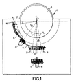
- an antenna 2 designed on the principle of the Luneberg lens and illustrated in Figure 1 , comprises essentially a sphere 4 consisting mainly of a dielectric material, and also receivers 6 and transmitters 8.
- the sphere 4 polarizes a plane wave incident at a focal point F which is outside the sphere 4 and where a receiver 6 will therefore be placed.
- a wave transmitted in the direction of the sphere 4 by a point source (such as a transmitter 8) located at the focal point F will generate a plane wave.
- the focal point F is variable as a function of the direction of the incident or transmitted plane wave.
- the electromagnetic waves carrying the signals are considered as being plane waves, the direction of which is a straight line connecting the antenna to the satellite.
- the antenna 2 is more particularly intended for communication with low-altitude satellites, the orbit of which is at an altitude below the altitude of geostationary satellites. Such satellites are movable in the terrestrial reference system. The direction of the incident and transmitted plane waves is therefore variable. The receiver 6 and the transmitters 8 are movable, so as to be positioned at any moment at the focal point F assigned to the direction of the incident wave.
- the fact that these satellites move in a terrestrial reference system implies, moreover, that they may disappear from the field of vision, for example by passing below the skyline. Consequently, there is provision for using constellations of satellites which all transmit the same signal.
- the antenna 2 is equipped with two transmitter/receiver assemblies 10 which take over from one another so as to obtain a continuous reception signal and always have the possibility of transmitting towards a satellite of the constellation.
- the two transmitter/receiver assemblies 10 are mounted on a complex mechanical system consisting of the following elements:
- Each transmitter/receiver assembly 10 is mounted on a respective elbow arm 16.
- Figure 1 shows only one shoulder arm 14 and only one elbow arm 16 for the sake of clarity in the drawing.
- the rotational position of the base 12 in relation to the plinth 11, of each shoulder arm 14 in relation to the base 12 and of each elbow arm 16 in relation to the associated shoulder arm 14 is variable by means of as many motors 18, 20, 22 mounted on each axis of rotation. More specifically, the motor 18 allows a rotational movement of the base 12, each motor 20 allows a rotational movement of the corresponding shoulder arm 14 in relation to the base 12 and each motor 22 allows a rotational movement of the elbow arm 16 in relation to the shoulder arm 14 on which the said elbow arm is mounted.
- the motors 18, 20, 22 are controlled by means of an electronic control circuit (not shown) which displaces the various elements, in such a way that the two transmitter/receiver systems 10 are each placed at a focal point F assigned to the reception direction of a satellite of the constellation.
- the plinth 11 contains the electrical supply, the electronic control circuit and the circuit for processing the signals received and transmitted.
- the following electrical connections are made between the plinth 11 and the transmitter/receiver assembly 10:
- the supply cables 28, 30 and the control cables 32 are combined in a flat sheet-like cable (third cable) 34 (FFC, standing for Flexible Flat Cable).
- third cable 34 FFC, standing for Flexible Flat Cable
- a cable reel 36 is provided at each joint.
- a reel 36 is described below, with reference to Figures 2 , 3a , 3b and 4 , which relates to a base 12/shoulder arm 14 joint or shoulder arm 14/elbow arm 16 joint respectively, with a knowledge that the reels 36 relating to these joints are produced on the same principle.
- the term "lower arm 38" will denote that of the two arms of the joint which is mechanically nearest to the plinth 11 (base 12 or shoulder arm 14 respectively) and the term “upper arm 40” will denote that which is furthest away (shoulder arm 14 or elbow arm 16 respectively).
- the joint between the lower arm (first component) 38 and the upper arm (second component) 40 consists mainly of a shaft 42 fixed to the upper arm 40.
- the shaft 42 is mounted on the upper arm 40 in the region of a hub 41 which extends from the lower face 74 of the upper arm 40 (that is to say, the face turned towards the lower arm 38).
- the shaft 40 is driven in rotation by a motor 44 (which is therefore the motor 20 or the motor 22, depending on the joint).
- the motor 44 is fixed to the lower arm 38.
- the motor 44 is mounted on the lower face 46 of the lower arm 38 (that is say, on the face opposite to the upper arm 40); the rotary shaft 42 passes through the lower arm 38, with an anti-friction ring 48 interposed, and then the upper arm 40.
- the rotary shaft 42 is fastened to the upper arm 40 by means of a nut 50 mounted at the upper end of the shaft 42 and bearing on the upper face 52 of the upper arm 40 (that is say, the face opposite to the lower arm 38).
- the terms “radial” and “axial” are understood as being in relation to the axis Y of the rotary shaft 42.
- the terms “lower” and “below” mean, in relation to the direction of the axis Y, in the direction from the upper arm 40 towards the lower arm 38.
- the terms “upper” and “above” mean, in relation to the direction of the axis Y, in the direction from the lower arm 38 towards the upper arm 40.
- the reel 36 comprises an annular lower receptacle 54 delimited radially by a small-diameter cylindrical wall 56 of axis Y and by a large-diameter cylindrical wall 58 of axis Y.
- the lower receptacle 54 comprises a lower magazine (second magazine) 60 which receives a second coaxial cable 26 and an intermediate magazine (first magazine) 62 which receives the first coaxial cable 24.
- the lower receptacle 54 is delimited axially by a lower wall 68 perpendicular to the axis Y and formed by the upper face of the lower arm 38.
- the cylindrical walls 56, 58 are likewise produced integrally in the lower arm 38.
- the lower magazine 60 and the intermediate magazine 62 each have a height (parallel to the axis Y) which is very slightly greater than the diameter of the coaxial cables 24, 26, for example 0.2 mm greater.
- the coaxial cable 24, 26 is wound spirally about the axis Y over a single thickness, thus producing concentric turns, the radius of which varies along the cable 24, 26.
- the reel 36 also comprises an annular upper receptacle 55 delimited by a small-diameter cylindrical wall 64 of axis Y and by a large-diameter cylindrical wall 66 of axis Y.
- the upper receptacle 55 defines an upper magazine (third magazine) which receives the flat sheet-like cable 34.
- the height of the upper magazine 55 corresponds to the width of the flat sheet-like cable 34.
- the flat cable 34 is would spirally about the axis Y, the width of the flat cable 34 extending parallel to the axis Y.
- the anti-friction ring 48 has, at its upper end, an annular wing 49 which makes it possible for it to be retained axially between the lower arm 38 and the upper arm 40. More specifically, the upper face of the wing 49 bears axially on a face of the hub 41 and the lower face of the wing 49 bears axially on the small-diameter cylindrical wall 56 of the lower receptacle 54.
- the separation between the lower magazine 60 and the intermediate magazine 62 is made by a first flange 70 of annular general shape, arranged perpendicularly to the axis Y and fixed in terms of rotation to the upper arm 40.
- the separation between the intermediate magazine 62 and the upper magazine 55 is made by a second flange 72 of annular general shape, arranged perpendicularly to the axis Y and fixed in terms of rotation to the lower arm 38.
- the lower magazine 60 and the intermediate magazine 62 are delimited radially by the large-diameter cylindrical wall 58 of the lower receptacle 54, on the one hand, and by a collar 57 produced in the upper arm 40 at the end of the hub 41, on the other hand.
- the collar 57 has a cylindrical slope of axis Y.
- the collar 57 has a radius greater than the radius of the small-diameter cylindrical wall 56 of the lower receptacle 54, but a radius smaller than the outer radius of the hub 41.
- the component which forms the second flange 72 also carries the large-diameter cylindrical wall 66 of the upper receptacle 55.
- the upper wall of the upper receptacle 55 is produced by a part of the lower face 74 of the upper arm 40.
- the small-diameter cylindrical wall 64 of the upper receptacle 55 is formed by the outer surface of the hub 41.
- Each coaxial cable 24, 26 penetrates into its respective magazine 62, 60 by means of an orifice 76 in the large-diameter cylindrical wall 58 of the lower receptacle 54.
- Each coaxial cable 24, 26 is immobilized at the orifice 76.
- each coaxial cable 24, 26 passes through the upper arm 40 (and thereby through the upper magazine 55) by means of a respective duct 78, 80 produced in the hub 41 and parallel to the axis Y.
- Each coaxial cable 24, 26 is immobilized relative to its respective duct 78, 80, in such a way that that part of each coaxial cable 24, 26 which is level with the upper arm 40, outside the lower receptacle 54 and the ducts 78, 80, is fixed in relation to the upper arm 40.
- the second cable 26 contained in the lower magazine 60 passes through the first flange 70 at a hole 71, the intermediate magazine 62 and the upper arm 40 by means of the duct 80. It will therefore be understood that it is necessary for the first flange 70 to be fixed to the upper arm 40, as specified above.
- the two ends 82, 84 of that part of the cable which is located in the magazine 62, 60 are therefore fixed, one 82 in relation to the lower arm 38 and the other 84 in relation to the upper arm 40.
- the radius at each point of the cable 24, 26 is adjusted mechanically, in such a way that the angular distance between the two ends 82, 84 corresponds to that length of the cable 24, 26 which is located in the magazine 62, 60 (this length being constant).
- Figures 3a and 3b illustrate respectively the coaxial cable 24 in two different arrangements due to a rotation of the upper arm 40 by one turn in relation to the lower arm 38.
- the radial dimension of the magazine 62, 60 are determined in such a way that the latter accepts all the variations in radius which are liable to occur.
- the ratio of the inner and outer radii of the magazine is 4.3 for the possibility of executing 1 turn and 6.3 for the possibility of executing 3 turns.
- a flat sheet-like cable 34 passes through the large-diameter wall 66 of the upper magazine 55 at an orifice 85 and through the upper arm 40 via a slot 86 at which it is immobilized.
- the width of the flat sheet-like cable 34 (that is to say, its dimension according to which the various cables 28, 30, 32 are aligned) extends parallel to the axis Y of the reel 36.
- the flat sheet-like cable 34 is wound spirally about the axis Y.
- the two ends of that part of the flat sheet-like cable 34 which is located in the upper magazine 55 are fixed (one at the orifice 85 and therefore in relation to the second flange 72 fixed to the lower arm 38; the other at the slot 86 and therefore in relation to the upper arm 40), in such a way that the behaviour of the flat sheet-like cable 34 during the rotation of one arm in relation to the other is similar to the behaviour described above with regard to the coaxial cables 24, 26.
- the reel 36 which has just been described makes it possible at reasonable cost to make a particularly reliable electrical connection at the lower arm 38/upper arm 40 joint, especially because this solution does not require the use of any link-up since the cables 24, 26, 34, especially the coaxial cables 24, 26, are not interrupted when they pass through the joint.
- the number of components forming the reel 36 is reduced to a minimum, especially due to the fact that the large-diameter walls 58, 66 of the lower magazine 54 and of the upper magazine 55 and the collar 57 are produced respectively on the lower arm 38, on the second flange 72 and on the hub 41.
Landscapes
- Electric Cable Arrangement Between Relatively Moving Parts (AREA)
- Variable-Direction Aerials And Aerial Arrays (AREA)
- Support Of Aerials (AREA)
- Manipulator (AREA)
Applications Claiming Priority (2)
| Application Number | Priority Date | Filing Date | Title |
|---|---|---|---|
| FR9912754 | 1999-10-13 | ||
| FR9912754 | 1999-10-13 |
Publications (2)
| Publication Number | Publication Date |
|---|---|
| EP1093201A1 EP1093201A1 (en) | 2001-04-18 |
| EP1093201B1 true EP1093201B1 (en) | 2009-12-09 |
Family
ID=9550874
Family Applications (1)
| Application Number | Title | Priority Date | Filing Date |
|---|---|---|---|
| EP00402719A Expired - Lifetime EP1093201B1 (en) | 1999-10-13 | 2000-10-04 | Cable reel and electromagnetic wave communication device equipped with such a reel |
Country Status (5)
| Country | Link |
|---|---|
| US (1) | US6595452B1 (https=) |
| EP (1) | EP1093201B1 (https=) |
| JP (1) | JP4518354B2 (https=) |
| CN (1) | CN1238939C (https=) |
| DE (1) | DE60043488D1 (https=) |
Cited By (1)
| Publication number | Priority date | Publication date | Assignee | Title |
|---|---|---|---|---|
| CN108064430A (zh) * | 2015-06-25 | 2018-05-22 | 艾尔斯潘网络公司 | 可旋转天线设备 |
Families Citing this family (10)
| Publication number | Priority date | Publication date | Assignee | Title |
|---|---|---|---|---|
| US7434469B2 (en) * | 2006-05-26 | 2008-10-14 | Rosemount Inc. | Remote seal installation improvements |
| US20130289542A1 (en) * | 2012-04-30 | 2013-10-31 | Elekta Ab (Publ) | Arrangement for supporting one or more cables, wires or hoses |
| CN102856627B (zh) * | 2012-09-17 | 2014-12-10 | 南京恩瑞特实业有限公司 | 一种多层组合天线座 |
| US9837805B2 (en) | 2014-05-09 | 2017-12-05 | Ruggedreel Inc. | System and apparatus for electrically coupling to a cable on a rotatable reel using optical communication devices |
| FR3024384A1 (fr) * | 2014-07-30 | 2016-02-05 | Aldebaran Robotics | Amelioration de l'assemblage d'un robot a caractere humanoide |
| GB2539724A (en) * | 2015-06-25 | 2016-12-28 | Airspan Networks Inc | A rotable antenna apparatus |
| US10669023B2 (en) | 2016-02-19 | 2020-06-02 | Raytheon Company | Tactical aerial platform |
| DE102019001311A1 (de) * | 2019-02-23 | 2020-08-27 | Leopold Kostal Gmbh & Co. Kg | Wickelfederkassette |
| CN215732537U (zh) * | 2021-07-23 | 2022-02-01 | 东莞市承越电子科技有限公司 | 单向随意拉数据线 |
| CN113800339B (zh) * | 2021-09-16 | 2022-05-17 | 中国电子科技集团公司第三十八研究所 | 一种包括滑轮式管路自动卷绕装置的天线 |
Family Cites Families (32)
| Publication number | Priority date | Publication date | Assignee | Title |
|---|---|---|---|---|
| US3337695A (en) | 1964-09-10 | 1967-08-22 | William R Brown | Reel for starter jump cables |
| FR2249458A1 (en) | 1973-10-24 | 1975-05-23 | Centre Nat Etd Spatiales | Connector lead take-up bobbin - gives connection between rotating body and measuring devices |
| US4713497A (en) | 1982-06-03 | 1987-12-15 | Smith John N | Self-storing cord and reel assemblies for shielded cables |
| JPS6279993A (ja) * | 1985-10-01 | 1987-04-13 | 株式会社東芝 | ロボツトの旋回駆動装置 |
| US4744763A (en) * | 1986-04-15 | 1988-05-17 | Furukawa Electric Co., Ltd. | Connector device for a transmission line connecting two relatively rotating members |
| US4722690A (en) * | 1987-03-17 | 1988-02-02 | Methode Electronics, Inc. | Clock spring interconnector |
| US4824396A (en) * | 1987-05-27 | 1989-04-25 | Alps Electric Co., Ltd. | Electrical connection apparatus |
| US4904190A (en) * | 1988-10-03 | 1990-02-27 | Molex Incorporated | Electrical connector assembly for vehicular steering wheel |
| JPH0720868Y2 (ja) * | 1988-12-22 | 1995-05-15 | アルプス電気株式会社 | ケーブルリール |
| JP2507808B2 (ja) * | 1989-05-31 | 1996-06-19 | 古河電気工業株式会社 | コネクタ装置 |
| US5098028A (en) | 1989-06-05 | 1992-03-24 | Alps Electric Co., Ltd. | Clock spring connector including cable stowage grooves |
| DE4031235A1 (de) * | 1990-03-02 | 1991-09-12 | Thomas & Betts Corp | Verbindungsvorrichtung |
| US5049082A (en) * | 1990-03-15 | 1991-09-17 | Imo Industries, Inc. | Thru wire helm assembly |
| JP2999578B2 (ja) * | 1990-06-14 | 2000-01-17 | アルプス電気株式会社 | ケーブルリール |
| JP2528091Y2 (ja) * | 1990-06-27 | 1997-03-05 | 日立電線株式会社 | 平型ケーブル収納箱 |
| JPH0711427Y2 (ja) * | 1990-10-24 | 1995-03-15 | 古河電気工業株式会社 | 回転コネクタ |
| WO1992008254A1 (en) * | 1990-10-29 | 1992-05-14 | Thomson Consumer Electronics S.A. | Method for the fabrication of lenses with a variable refraction index |
| JP2538866Y2 (ja) * | 1991-11-15 | 1997-06-18 | 古河電気工業株式会社 | 回転コネクタ |
| JPH065338U (ja) * | 1992-06-25 | 1994-01-21 | 日本無線株式会社 | 回転体における給電用配線保護装置 |
| JPH0644077U (ja) * | 1992-11-12 | 1994-06-10 | 古河電気工業株式会社 | 回転体と固定体間の伝送装置 |
| JPH076841A (ja) * | 1993-06-18 | 1995-01-10 | Sumitomo Electric Ind Ltd | 電気信号伝達装置 |
| JPH07226275A (ja) * | 1994-02-14 | 1995-08-22 | Toyota Motor Corp | ケーブルリール |
| KR0140588B1 (ko) * | 1994-03-09 | 1998-07-01 | 가다오까 마사다까 | 회전콘넥터 |
| JPH0865026A (ja) * | 1994-08-25 | 1996-03-08 | Ricoh Co Ltd | 回転可倒式アンテナの給電線 |
| US5645441A (en) * | 1995-05-18 | 1997-07-08 | Niles Parts Co., Ltd. | Rotary connector device |
| JP3634470B2 (ja) * | 1995-11-09 | 2005-03-30 | 矢崎総業株式会社 | 相対回転部材間継電装置 |
| JPH09148026A (ja) * | 1995-11-24 | 1997-06-06 | Yazaki Corp | 相対回転部材間継電装置 |
| DE19635236C1 (de) | 1996-08-30 | 1998-03-12 | Siemens Ag | Gewichtsausgleichsvorrichtung, insbesondere für eine medizinische Röntgeneinrichtung |
| JP3001091B2 (ja) * | 1996-12-11 | 2000-01-17 | 富士通電装株式会社 | 光ケーブル余長処理装置 |
| JPH10294159A (ja) * | 1997-04-18 | 1998-11-04 | Yazaki Corp | 相対回転部材間継電装置 |
| US5863010A (en) * | 1997-10-16 | 1999-01-26 | General Electric Company | Apparatus for routing resilient cable across rotary joint |
| JPH10341521A (ja) * | 1998-06-03 | 1998-12-22 | Alps Electric Co Ltd | ケーブルリール |
-
2000
- 2000-10-04 EP EP00402719A patent/EP1093201B1/en not_active Expired - Lifetime
- 2000-10-04 DE DE60043488T patent/DE60043488D1/de not_active Expired - Lifetime
- 2000-10-09 CN CN00130656.1A patent/CN1238939C/zh not_active Expired - Fee Related
- 2000-10-10 US US09/685,520 patent/US6595452B1/en not_active Expired - Fee Related
- 2000-10-13 JP JP2000314176A patent/JP4518354B2/ja not_active Expired - Fee Related
Cited By (2)
| Publication number | Priority date | Publication date | Assignee | Title |
|---|---|---|---|---|
| CN108064430A (zh) * | 2015-06-25 | 2018-05-22 | 艾尔斯潘网络公司 | 可旋转天线设备 |
| CN108064430B (zh) * | 2015-06-25 | 2021-04-13 | 艾尔斯潘网络公司 | 可旋转天线设备 |
Also Published As
| Publication number | Publication date |
|---|---|
| EP1093201A1 (en) | 2001-04-18 |
| JP2001144519A (ja) | 2001-05-25 |
| CN1238939C (zh) | 2006-01-25 |
| JP4518354B2 (ja) | 2010-08-04 |
| US6595452B1 (en) | 2003-07-22 |
| CN1293464A (zh) | 2001-05-02 |
| DE60043488D1 (de) | 2010-01-21 |
Similar Documents
| Publication | Publication Date | Title |
|---|---|---|
| EP1093201B1 (en) | Cable reel and electromagnetic wave communication device equipped with such a reel | |
| US11264716B2 (en) | Actuator gearbox with selectable linkages | |
| EP0296322B1 (en) | An airborne antenna and a system for mechanically steering an airborne antenna | |
| EP3852235A1 (en) | Contactless power supply and data communication device, and system having rotation-drive unit, using same | |
| EP0687388B1 (en) | Drive arrangement for mechanically-steered antennas | |
| US4574289A (en) | Rotary scan antenna | |
| EP1241732B9 (en) | Antenna apparatus and waveguide rotary coupler with inductive transformer | |
| JPS5819162B2 (ja) | マイクロ波アンテナ装置 | |
| US6262687B1 (en) | Tracking antenna and method | |
| EP1082778A2 (en) | Multibeam satellite communication antenna | |
| US5519409A (en) | Plane array antenna for receiving satellite broadcasting | |
| JP3965452B2 (ja) | 圧力センサを有するホイール組立体 | |
| CN1157822C (zh) | 抛物面天线的变频装置 | |
| EP0449158B1 (en) | Fine pointing system of a reflector type focussing antenna | |
| US7089791B2 (en) | Wheel assembly equipped with a tachometer | |
| EP1099274B1 (en) | Device for antenna systems | |
| CN201054385Y (zh) | 平板式卫星自动跟踪天线系统 | |
| CN1964137A (zh) | 平板式卫星自动跟踪天线系统 | |
| EP2115899B1 (en) | Optimized receive antenna and system for precision gps-at-geo navigation | |
| CN101924274B (zh) | 圆偏波接收用自动卫星跟踪天线系统 | |
| MXPA96004653A (es) | DISPOSITIVO TRANSMISOR DE SEnALES. | |
| CN223757694U (zh) | 天线组件、飞行器及飞行器系统 | |
| Belostotskaya et al. | The antenna system of Mars-rover | |
| EP3573180B1 (en) | Antenna with single motor positioning and related methods | |
| JPH083049Y2 (ja) | 移動体搭載のアンテナ装置 |
Legal Events
| Date | Code | Title | Description |
|---|---|---|---|
| PUAI | Public reference made under article 153(3) epc to a published international application that has entered the european phase |
Free format text: ORIGINAL CODE: 0009012 |
|
| AK | Designated contracting states |
Kind code of ref document: A1 Designated state(s): DE ES FR GB IT |
|
| AX | Request for extension of the european patent |
Free format text: AL;LT;LV;MK;RO;SI |
|
| 17P | Request for examination filed |
Effective date: 20011011 |
|
| AKX | Designation fees paid |
Free format text: DE ES FR GB IT |
|
| 17Q | First examination report despatched |
Effective date: 20080917 |
|
| GRAP | Despatch of communication of intention to grant a patent |
Free format text: ORIGINAL CODE: EPIDOSNIGR1 |
|
| GRAS | Grant fee paid |
Free format text: ORIGINAL CODE: EPIDOSNIGR3 |
|
| GRAA | (expected) grant |
Free format text: ORIGINAL CODE: 0009210 |
|
| AK | Designated contracting states |
Kind code of ref document: B1 Designated state(s): DE ES FR GB IT |
|
| REG | Reference to a national code |
Ref country code: GB Ref legal event code: FG4D |
|
| REF | Corresponds to: |
Ref document number: 60043488 Country of ref document: DE Date of ref document: 20100121 Kind code of ref document: P |
|
| PG25 | Lapsed in a contracting state [announced via postgrant information from national office to epo] |
Ref country code: ES Free format text: LAPSE BECAUSE OF FAILURE TO SUBMIT A TRANSLATION OF THE DESCRIPTION OR TO PAY THE FEE WITHIN THE PRESCRIBED TIME-LIMIT Effective date: 20100320 |
|
| PLBE | No opposition filed within time limit |
Free format text: ORIGINAL CODE: 0009261 |
|
| STAA | Information on the status of an ep patent application or granted ep patent |
Free format text: STATUS: NO OPPOSITION FILED WITHIN TIME LIMIT |
|
| 26N | No opposition filed |
Effective date: 20100910 |
|
| PGFP | Annual fee paid to national office [announced via postgrant information from national office to epo] |
Ref country code: GB Payment date: 20100928 Year of fee payment: 11 |
|
| PGFP | Annual fee paid to national office [announced via postgrant information from national office to epo] |
Ref country code: DE Payment date: 20101022 Year of fee payment: 11 |
|
| PG25 | Lapsed in a contracting state [announced via postgrant information from national office to epo] |
Ref country code: IT Free format text: LAPSE BECAUSE OF FAILURE TO SUBMIT A TRANSLATION OF THE DESCRIPTION OR TO PAY THE FEE WITHIN THE PRESCRIBED TIME-LIMIT Effective date: 20091209 |
|
| PGFP | Annual fee paid to national office [announced via postgrant information from national office to epo] |
Ref country code: FR Payment date: 20111103 Year of fee payment: 12 |
|
| GBPC | Gb: european patent ceased through non-payment of renewal fee |
Effective date: 20121004 |
|
| REG | Reference to a national code |
Ref country code: FR Ref legal event code: ST Effective date: 20130628 |
|
| PG25 | Lapsed in a contracting state [announced via postgrant information from national office to epo] |
Ref country code: GB Free format text: LAPSE BECAUSE OF NON-PAYMENT OF DUE FEES Effective date: 20121004 Ref country code: DE Free format text: LAPSE BECAUSE OF NON-PAYMENT OF DUE FEES Effective date: 20130501 |
|
| REG | Reference to a national code |
Ref country code: DE Ref legal event code: R119 Ref document number: 60043488 Country of ref document: DE Effective date: 20130501 |
|
| PG25 | Lapsed in a contracting state [announced via postgrant information from national office to epo] |
Ref country code: FR Free format text: LAPSE BECAUSE OF NON-PAYMENT OF DUE FEES Effective date: 20121031 |