EP1093099A2 - Automatische Detektion und Meldesystem von gefährlichen oder Notsituationen - Google Patents
Automatische Detektion und Meldesystem von gefährlichen oder Notsituationen Download PDFInfo
- Publication number
- EP1093099A2 EP1093099A2 EP00203523A EP00203523A EP1093099A2 EP 1093099 A2 EP1093099 A2 EP 1093099A2 EP 00203523 A EP00203523 A EP 00203523A EP 00203523 A EP00203523 A EP 00203523A EP 1093099 A2 EP1093099 A2 EP 1093099A2
- Authority
- EP
- European Patent Office
- Prior art keywords
- alarm
- detection
- control unit
- signalling system
- signalling
- Prior art date
- Legal status (The legal status is an assumption and is not a legal conclusion. Google has not performed a legal analysis and makes no representation as to the accuracy of the status listed.)
- Pending
Links
- 230000011664 signaling Effects 0.000 title claims abstract description 61
- 238000001514 detection method Methods 0.000 title claims abstract description 48
- 238000004891 communication Methods 0.000 claims abstract description 17
- 230000004913 activation Effects 0.000 claims description 16
- 230000005540 biological transmission Effects 0.000 claims description 14
- 230000009849 deactivation Effects 0.000 claims description 8
- 239000000779 smoke Substances 0.000 claims description 8
- 230000036541 health Effects 0.000 claims description 7
- 230000001755 vocal effect Effects 0.000 claims description 6
- 230000007257 malfunction Effects 0.000 claims description 5
- 230000003213 activating effect Effects 0.000 claims description 4
- 230000007547 defect Effects 0.000 claims description 4
- 238000012423 maintenance Methods 0.000 claims description 4
- 230000015572 biosynthetic process Effects 0.000 claims description 3
- 238000003786 synthesis reaction Methods 0.000 claims description 3
- 230000016571 aggressive behavior Effects 0.000 claims description 2
- 230000000007 visual effect Effects 0.000 claims 1
- 239000007789 gas Substances 0.000 description 16
- 238000009434 installation Methods 0.000 description 11
- 238000000034 method Methods 0.000 description 10
- 230000000737 periodic effect Effects 0.000 description 10
- VNWKTOKETHGBQD-UHFFFAOYSA-N methane Chemical compound C VNWKTOKETHGBQD-UHFFFAOYSA-N 0.000 description 8
- WHXSMMKQMYFTQS-UHFFFAOYSA-N Lithium Chemical compound [Li] WHXSMMKQMYFTQS-UHFFFAOYSA-N 0.000 description 7
- 229910052744 lithium Inorganic materials 0.000 description 7
- UGFAIRIUMAVXCW-UHFFFAOYSA-N Carbon monoxide Chemical compound [O+]#[C-] UGFAIRIUMAVXCW-UHFFFAOYSA-N 0.000 description 5
- 229910002091 carbon monoxide Inorganic materials 0.000 description 5
- 238000012360 testing method Methods 0.000 description 4
- 238000003745 diagnosis Methods 0.000 description 3
- 230000009977 dual effect Effects 0.000 description 3
- XLYOFNOQVPJJNP-UHFFFAOYSA-N water Substances O XLYOFNOQVPJJNP-UHFFFAOYSA-N 0.000 description 3
- 238000012790 confirmation Methods 0.000 description 2
- 238000010586 diagram Methods 0.000 description 2
- 230000000694 effects Effects 0.000 description 2
- 238000012795 verification Methods 0.000 description 2
- 229910005813 NiMH Inorganic materials 0.000 description 1
- 241000269400 Sirenidae Species 0.000 description 1
- 239000002390 adhesive tape Substances 0.000 description 1
- 238000004458 analytical method Methods 0.000 description 1
- 230000003254 anti-foaming effect Effects 0.000 description 1
- 230000004888 barrier function Effects 0.000 description 1
- 230000008859 change Effects 0.000 description 1
- 238000004140 cleaning Methods 0.000 description 1
- 238000009792 diffusion process Methods 0.000 description 1
- 238000005516 engineering process Methods 0.000 description 1
- 239000002360 explosive Substances 0.000 description 1
- 230000010354 integration Effects 0.000 description 1
- 230000007774 longterm Effects 0.000 description 1
- 239000000463 material Substances 0.000 description 1
- 238000012544 monitoring process Methods 0.000 description 1
- 230000002093 peripheral effect Effects 0.000 description 1
- 229920000515 polycarbonate Polymers 0.000 description 1
- 239000004417 polycarbonate Substances 0.000 description 1
- 230000002035 prolonged effect Effects 0.000 description 1
- 230000008439 repair process Effects 0.000 description 1
- 230000000284 resting effect Effects 0.000 description 1
- 238000004092 self-diagnosis Methods 0.000 description 1
- 238000010257 thawing Methods 0.000 description 1
- 239000002341 toxic gas Substances 0.000 description 1
- 238000009423 ventilation Methods 0.000 description 1
Images


Classifications
-
- G—PHYSICS
- G08—SIGNALLING
- G08B—SIGNALLING OR CALLING SYSTEMS; ORDER TELEGRAPHS; ALARM SYSTEMS
- G08B13/00—Burglar, theft or intruder alarms
- G08B13/22—Electrical actuation
-
- G—PHYSICS
- G08—SIGNALLING
- G08B—SIGNALLING OR CALLING SYSTEMS; ORDER TELEGRAPHS; ALARM SYSTEMS
- G08B25/00—Alarm systems in which the location of the alarm condition is signalled to a central station, e.g. fire or police telegraphic systems
- G08B25/01—Alarm systems in which the location of the alarm condition is signalled to a central station, e.g. fire or police telegraphic systems characterised by the transmission medium
- G08B25/08—Alarm systems in which the location of the alarm condition is signalled to a central station, e.g. fire or police telegraphic systems characterised by the transmission medium using communication transmission lines
-
- G—PHYSICS
- G08—SIGNALLING
- G08B—SIGNALLING OR CALLING SYSTEMS; ORDER TELEGRAPHS; ALARM SYSTEMS
- G08B25/00—Alarm systems in which the location of the alarm condition is signalled to a central station, e.g. fire or police telegraphic systems
- G08B25/14—Central alarm receiver or annunciator arrangements
Definitions
- the present invention refers to an automatic detection and signalling system of dangerous or emergency situations.
- teleassistance electronic devices particularly of use in aiding persons in need of help, which are able to send a request for help through a telephone dialer which dials a series of telephone numbers in order, programmable by the user, after pressing a certain push button of a portable radio remote control.
- the aim of the present invention is therefore to demonstrate an automatic detection and signalling system of dangerous or emergency situations that, in the event of serious and immediate danger, allows the timely sending of a request for help to the competent public services.
- Another aim of the present invention is to demonstrate an automatic detection and signalling system of dangerous or emergency situations which allows, under certain conditions, the timely signalling of an alarm, identifying in any case the place where the alarm sounded.
- a further aim of the present invention is to produce an automatic detection and signalling system of dangerous or emergency situations which is easy and cheap to produce, without using complex or expensive technologies, using simple circuit solutions and known electronic components.
- the system which is the object of the present invention, includes a control unit with a telephone dialer and a set of peripheral detectors (anti-intrusion detectors, fire detectors, methane gas detectors, carbon monoxide detectors and flood detectors).
- peripheral detectors anti-intrusion detectors, fire detectors, methane gas detectors, carbon monoxide detectors and flood detectors.
- the control unit subsequently includes an extractable emergency lamp to supply light in the event of a blackout.
- the system can be produced in a wall-mounted or external version (wall or table-top) and, upon activation by a user pressing a push button, the system automatically sends, through a telephone network, an alarm voice announcement to an operations centre which puts the requests for assistance through to the personnel in charge, depending on the type of alarm sent.
- control unit is connected to the normal telephone network for communicating with a call-centre and to the 230 Volt electric network for the power supply and charging of the battery relating to the emergency lamp; alternatively the control unit may be completely battery powered in the wall and table-top versions.
- radio controls are envisaged, some optional, among which a radio remote control to set the control unit in a surveillance status and bring it back to rest status, acoustic alarm signallers, a viva voce device and a radio receiver to pick up signals coming from the detectors.
- 10 generically indicates a control unit of the automatic detection and signalling system of dangerous or emergency situations, which is subject of the present invention.
- the detection and signalling system of dangerous or emergency situations is an electronic device which manages, in domestic situations, the functions of teleassistance, anti-intrusion and ambient alarms (gas, fire and flood detection).
- the control unit 10 incorporates, in a single object, the alarm signalling devices such as a siren, and the communication devices for the remote signalling of the alarm, as a telephone dialer with a viva voce system.
- the alarm signalling devices such as a siren
- the communication devices for the remote signalling of the alarm as a telephone dialer with a viva voce system.
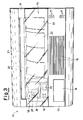
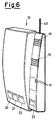
- the system is available in a wall-mounted version as shown in figures 1, 2 and 3 or a wired wall or table-top version (respectively represented by figures 5 and 6).
- figure 1 shows a control unit 10 of the wall-mounted version, the frame 11 of which includes a front plate 13, which is modularly compatible with a cover 12.
- the cover 12 is provided in order to protect additional electrical equipment, namely meters, switches or circuit breaker; alternatively, the frame 11 can be shaped so as to exclusively include the electronic equipments and the function keys of the detection system as shown in figures 2-4.
- the control unit 10 is powered by the conventional 230 Volt electric network, in the wall-mounted version, or battery powered in the case of the wall and table-top versions, and is connected to a normal telephone line by a built-in automatic sequence switch for conventional telephone lines.
- the telephone dialer allows the automatic connection to an operations centre or the sending of voice calls (pre-recorded vocal alarm messages) directly to programmed telephone numbers.
- control unit 10 has a shaped cover 14, which can be lifted upwards, giving access to a series of push buttons 20, 21, 22, 23, each complete with symbols and/or reference captions for the separate activation of different alarm types.
- the push buttons 20-22 start the automatic call to an operations centre through which is carried out, respectively, a request for health assistance (symbol: red cross), an emergency request made to the police following threats, acts of aggression or theft (symbol: SOS) and a request for urgent household maintenance, such as the services of a plumber, electrician or builder for urgent repairs (symbol: spanner).
- a request for health assistance symbol: red cross
- an emergency request made to the police following threats acts of aggression or theft
- SOS acts of aggression or theft
- a request for urgent household maintenance such as the services of a plumber, electrician or builder for urgent repairs
- the push button 23 can annul calls made by mistake.
- a grille 15 covers a viva voce device and an acoustic signaller while a container 16, which may be extracted from the front plate 13, has a slot 30 in which to put one or more remote controls 72, 82 which activate, via radio, all the functions permitted by the push button controls of unit 10.
- the remote control 82 alone commands the placing of the central unit in a surveillance status and rest status; the radio remote control 72 allows, in addition, the remote activation of teleassistance and the activation and deactivation of the anti-intrusion system with the possibility of radio connection with one or more anti-intrusion detectors (passive infrared and perimetric, for doors and windows) and ambient ones (gas, smoke and flood detectors) with the actuators of the system and with an exterior siren.
- one or more anti-intrusion detectors passive infrared and perimetric, for doors and windows
- ambient ones gas, smoke and flood detectors
- the control unit 10 manages, as a whole, a maximum number of 15 detectors, 2 exterior sirens and 2 alarm actuators, while an alarm siren and an acoustic signaller for user signalling are directly built into the unit.
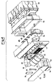
- the front plate 13 has a series of eight coloured LEDs, generically denoted by 17, providing visible signalling of the control unit 10 status, an alarm in progress and/or any operation defects or faults of the entire system, while the rear of the frame 11 contains the system electronic circuit boards 34 secured to a shaped container 36, in turn inserted inside the proper built-in box 38; in particular a voice synthesis device is included for maintenance and diagnostics signalling, a viva voce device for speaking over the telephone line, with the operations centre operator or the individual called, during the teleassistance calls, a microphone to allow ambient listening during the anti-intrusion alarm, and an anti-opening and tamper-proof protection device.
- a voice synthesis device is included for maintenance and diagnostics signalling
- a viva voce device for speaking over the telephone line, with the operations centre operator or the individual called, during the teleassistance calls
- a microphone to allow ambient listening during the anti-intrusion alarm
- an anti-opening and tamper-proof protection device
- an extractable and rechargeable autonomous emergency lamp used as a portable light torch, after removal from the control unit 10, in the event of a blackout;
- the torch is generically denoted by 18 in the figures 1, 3, 4.
- the 230 Volt electric network powers a built-in torch 18 battery, whose energy, once stored, is used to power a filament lamp or fluorescent tube 28 of the same portable torch, which can be, in such manner, switched on by switch 25 next to the screen 26 and therefore used to light the surroundings in the event of a blackout within the environment where the control unit 10 is installed.
- the 230 Volt electric network powers a series of NiMH rechargeable batteries built-in to the control unit, connected to the electronic circuit 34, giving the control unit 10 over 1 month's autonomy in the absence of the 230 Volt power supply.
- the LEDs may signal torch 18 operation in the presence and absence of the power supply.
- the unit 10 of the exterior versions of the system has an antenna 40 for radio communication with the detectors.
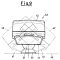
- a moveable wall mounted device not built-in, (as clearly shown by the dotted lines in figure 9) secured by means of a joint 47, on the back 41 of the device, connected to a fixing bracket 43 to wall 45, and including a passive infrared sensor with Fresnel lens 42 optimised for the volumetric coverage of a room in a building; the detector 48, if positioned high up on a side wall (approx. 2-2.5 metres off the floor, preferably in a corner), provides optimum coverage of a room in a building and communicates via radio with the control unit 10, immediately generating and transmitting an alarm in the event of the presence of a person moving in the area monitored by the sensors.
- the anti-intrusion detector 48 includes a non-rechargeable lithium battery for a minimum operating life of 4 years without replacement, a signalling LED 44 (usually red) for the verification of the volumetric coverage during the installation stage, an anti-opening and tamper-proof protection device and a push button 46 for the operation and installation test of the device.
- the anti-intrusion detector 48 is also equipped with a self-diagnosis circuit of rechargeable battery status, which is signalled by radio transmission to the control unit 10. In addition, the detector 48 transmits periodic monitoring data to the control unit 10.
- anti-intrusion detectors for doors and windows may be envisaged, of magnetic contact position type, for the perimetric protection of closed doors and windows.
- FIG 10 An example of such detectors is shown in figure 10; it comprises of two components 50, 51, which must be assembled so that they come together when the door or window is closed.
- the two components 50, 51 move apart upon opening the door (or window) sounding an alarm which the transmitting part immediately sends to the control unit 10; the detector is also equipped with an input alarm which may be connected to any type of exterior sensor by means of a suitable internal terminal board.
- Such detectors include, identical to the passive infrared ones, a radio transmitter for communication with control unit 10, a non-rechargeable lithium battery for a minimum operating life of 4 years without replacement, a signalling LED 52 (usually red) for the verification of its correct positioning during installation, with periodic transmission of its battery status and diagnosis to control unit 10, an anti-intrusion and tamper-proof protection device, a push button 53 for the detector test and installation.
- a flange is installed for fixing a permanent magnet to the framework of the doors or windows to be monitored, to be matched up with the detector.
- Another type of anti-intrusion detector which can be installed comprises of a detector for open doors and windows, typically for summer use; it concerns an operative device designed for the perimetric protection of living space near doors or windows, which is positioned directly outside the framework of the door or window to be protected.
- the device creates an invisible barrier, which, if crossed by a person, sets off an alarm signal and immediate transmission to the control unit 10; the device is designed so that air flows do not cause false alarms, and is thus suitable for the protection of doors and windows during the summer period, when, especially at night, rooms are left open to allow natural ventilation.
- a series of ambient detectors can be connected to the control unit 10, namely a gas and carbon monoxide detector with a built-in emergency lamp, a smoke detector and a flood detector (the latter is shown in figure 11).
- the gas detector is equipped with a dual sensor able to detect both the presence of methane gas (or other explosive gas) and carbon monoxide (or other toxic gas); it has a radio-transmitter to the control unit 10, a periodic transmitter to the same control unit 10 of detector status, a gas sensor operating only in the presence of a 230 Volt power supply, a direct control, in the event of alarm, with relay output and the availability of deflection contact (NC and NA), of an electro-valve or another electrical load, a linear emergency lamp with a 6W tube and 1 hour's autonomy in the absence of network power and a built-in acoustic alarm signal.
- the smoke detector is a device for ceiling mounting, not built-in, in compliance with current installation legislation; the device detects the presence of smoke based on the light diffusion principle (Tyndall effect). In the continued presence of smoke exceeding a certain intensity the detector sets off an alarm which is transmitted via radio to control unit 10.
- It includes a light reflection smoke sensor, a radio-transmitter for communicating with the control unit 10, a non-rechargeable lithium battery for a minimum operating life of 4 years, a push button for the testing and installation of the device, a periodic transmitter which sends to the control unit 10 a series of signals relating to the detector status with battery operation diagnosis and a built-in acoustic alarm signaller.
- the flood detector is a device for wall mounting, with the lower end 60 resting on the floor 61, as clearly visible from figure 11; the device includes a suitable sensor which, at the lower end 60, detects the presence of a film of water on the floor 61 of at least 3-4 mm in height.
- the detector includes a water sensor, comprising of a resistivity meter, a radio-transmitter for transmitting to the control unit 10, a non-rechargeable lithium battery for a minimum operating life of 4 years, a push button 65 for the testing and installation of the device, a signalling LED 66 and a periodic transmitter for transmitting to the control unit 10 the operating status with battery diagnosis.
- the detection and signalling system may after all include a radio repeater 81, one or two exterior buzzers 73, one or two receivers with relay output 74 and two radio remote controls.
- the radio repeater 81 ensures the operation of the system under any installation conditions, also when radio transmission is difficult due to the distance between some system components and the control unit 10.
- the addition of one or more of these devices by the system installer always renders the system produced wholly functional and efficient.
- the radio repeater comes equipped with non-rechargeable batteries for a minimum operating life of 4 years, under normal operating conditions, and must be installed in the most suitable points to guarantee the coverage of the desired system.
- the exterior buzzer 73 is the alarm signaller device suitable for wall mounting outside the building in which the control unit 10 is installed; this incorporates the proper siren and flashlight.
- the device is built for wall installation with screws and dowels and does not require any wiring up to the mains network, since it is self-powered by independent batteries which guarantee long-term functioning.
- the exterior buzzer 73 includes a radio receiver of the alarm from control unit 10 and a radio-transmitter for transmitting to the control unit 10 signals relative to the tamper conditions and battery status, a non-rechargeable lithium battery for a minimum operating life of 4 years, an anti-opening and anti-removal protection device, an alarm signaller with an acoustic power of at least 100dB, a dual anti-foaming case comprising of a shockproof polycarbonate external shell and an internal galvanized frame.
- the receiver with relay output 74 is a device which receives alarms generated by control unit 10, able to operate a relay output, allowing the control of electric actuators of any kind.
- the device can be programmed by the control unit 10, so that it is activated following an alarm generated by one of the various possible causes, namely a break-in, tampering, presence of methane gas, carbon monoxide, fire or flooding. It includes a radio receiver of the alarm from the control unit 10 and a radio-transmitter for the control unit 10 of battery status, a non-rechargeable lithium battery for a minimum operating life of 4 years, an anti-opening and anti-intrusion protection device.
- the radio remote controls 72, 82 are of two types, a teleassistance remote control, 72 and a remote control for the activation or deactivation of the system 82.
- the teleassistance remote control, 72 is a single key radio remote control which is used to operate the alarm from anywhere in the building; it can be programmed to generate two different alarm types, corresponding to two push buttons 20, 21 of the control unit 10, of health and police assistance.
- the control unit 10 is programmed at the factory so that the radio remote control supplied activates the health assistance alarm.
- the activation and deactivation remote control of the entire system 82 is a dual key radio remote control and is used for the activation and deactivation of the surveillance status of the anti-intrusion system; by pressing a push button (usually red) the control unit 10 activates the system, whereas pressing a push button (usually green) puts the control unit 10 in a rest status.
- control unit 10 can be programmed so that, in the event of alarm, it is automatically connected to an operations centre for the reception and coordination of the alarms, or simply calls a list of telephone numbers, set by the user, to which vocal alarm signals are sent indicating the causes of the alarm generated.
- All teleassistance functions are always operative for any control unit 10 status; to use these functions it is sufficient to have the control unit 10 and the radio remote control 72 supplied for the request for assistance, allowing the remote activation of one of the scheduled teleassistance functions.
- the user presses the corresponding push button 20 of the control unit 10 or a radio remote control push button 72 programmed for this function.
- control unit 10 Immediately after pressing the push button of the control unit 10 or of the remote control 72, the control unit 10 provides confirmation for the client of alarm activation by means of short beeps and starts alarm transmission over the telephone line 70, according to the following methods.
- control unit 10 immediately sends a telephone call to the operations centre where, after about ten seconds, the client and alarm type are automatically identified and the operator coordinates the assistance by simultaneous viva voce communication with the client and by telephone with the helpers.
- the operations centre operator Immediately upon receipt of the alarm, the operations centre operator is able to consult, on a computer screen, a box containing the personal and anamnestic details of the client and the references in the case of alarm; therefore the operations centre can also notify the external references supplied by the client.
- control unit 10 sends a telephone call to the first telephone number programmed by the user and reproduces a synthesized voice announcement of health assistance.
- control unit 10 After the message has been repeated a few times, the control unit 10 automatically activates the viva voce mode, so the person called can communicate directly with whom has requested assistance.
- the same procedure can be started, through an appropriately assigned operations centre or by means of simple synthesized voice messages, after pressing push button 21 of the control unit 10, relating to a request for police intervention, or using the radio remote control 72 programmed for this function.
- control unit 10 can be programmed so that, after pressing push button 21, the control unit 10 carries out all the communication operations in silence, without activating acoustic signallers, exterior sensors 73 and/or the speaker in the viva voce mode (anti-theft alarm) or so that the same control unit 10 activates an acoustic signaller confirming the pressing of push button 21 (general alarm) or so that the control unit 10 immediately activates the buzzer 73 of the system (anti-aggression alarm to discourage any suspicious individuals present) and subsequently switches off the buzzer 73 when viva voce communication is started.
- the anti-intrusion devices monitor the security of the building by means of the volumetric detectors 48, appropriately installed in the various rooms, and the perimetric detectors 78, 79 installed at the points of entry; at least one remote control 82 is required to control the system for the connection/disconnection of the system and, in this manner, the system can be set, through the operation of the control unit 10, in various operating states: system deactivated (rest status), in which the control unit 10 only monitors in the event that tampering of the various system components does not occur, immediately activating a tamper alarm as soon as such a situation is detected in one of the system components.
- the control unit 10 is deactivated by pressing the green key of the remote control 82.
- control unit 10 When the system is activated, the control unit 10 is ready to manage break-in alarms; as soon as an alarm indication is received by any one of the system's anti-intrusion devices 48, 78, 79, the control unit 10 activates the exterior buzzer 73 and its communication devices. The control unit 10 is activated by pressing the red key of the remote control 82.
- the system can be operated in night mode, in which the control unit 10 is ready to manage break-in alarms, as soon as an alarm indication is received by one of the anti-intrusion devices belonging to the night zone of the system (such effect is defined during the system programming stage).
- the control unit 10 activates the buzzer 73 and its communication devices and is set to night mode by pressing a certain sequence of keys of the remote control 82. In any case, the green key of the remote control 82 must be pressed to reset to rest status.
- the following alarm causes can be operative in the event of anti-intrusion.
- the tamper information transmitted by the volumetric anti-intrusion detectors 48 or by the perimetric detectors 78, 79 immediately sets off an anti-intrusion alarm.
- the control unit 10 immediately activates its own siren, the exterior buzzer 73 and the other actuators 74 of the system; if the unit 10 is not activated no call results over the telephone line, whereas if the control unit 10 is activated, it is set to communication mode in the following manner.
- the activation of the control unit 10 allows the immediate transmission of a telephone call to the operations centre, from where the call is automatically redirected to the police with an indication of the cause of the alarm.
- the operations centre operator upon police request, is ready to supply useful information to optimise police intervention.
- the police can monitor any noises in the building by listening with the aid of a microphone.
- the operations centre operator is able to, upon police request, and following receipt of the alarm, immediately consult a box containing the personal details of the client and any references indicated by the same, which can be notified.
- control unit 10 sends the telephone call to the first telephone number programmed by the user and repeats a synthesized voice message relating to a tampering incident.
- control unit 10 After the message has been repeated a few times, the control unit 10 automatically activates the remote listening mode, so that the person called can check, through the microphone of the control unit 10, the presence of any noises in the building.
- the information of the presence of persons or information indicating violation of the perimeter protection is transmitted by the volumetric anti-intrusion detectors 48 immediately setting off an anti-intrusion alarm when the control unit 10 is activated.
- control unit Normally, the control unit immediately activates its own siren, the exterior buzzer 73 and the other actuators 74 of the system and, at the same time, starts communication over the telephone line, with the same methods previously described concerning the tamper alarm.
- control unit 10 it is possible to programme the control unit 10 so that, in the event of alarm, the operation allows immediate siren activation and, at the same time, the telephone call or immediate activation of the telephone call with the siren being activated after about 1 minute, or activation of the telephone call alone.
- the gas alarm is the condition which occurs automatically following the alarm transmission of a gas detector 77 (methane and carbon monoxide) with built-in emergency lamp.
- control unit 10 immediately sounds an alarm signal by means of the buzzer and if necessary controls also the exterior buzzer 73 and the other system actuators. At the same time, the control unit 10 starts alarm transmission in viva voce telephone line mode according to the procedure described previously.
- the fire alarm is the condition which automatically occurs following alarm transmission by a smoke detector 76.
- control unit 10 immediately generates an alarm signal by means of the siren and if necessary controls also the exterior buzzer 73 and the other system actuators. At the same time, the control unit 10 starts alarm transmission in viva voce telephone line mode according to the procedure described previously.
- the flood alarm is the condition which occurs automatically following the alarm transmission of flood detectors 75.
- control unit 10 immediately generates an alarm signal by means of the siren and if necessary controls also the exterior buzzer 73 and the other system actuators, in particular a relay actuator may be controlled 74, which closes a solenoid valve of the water system).
- control unit 10 starts alarm transmission in viva voce telephone line mode, according to the same call procedure to an operations centre or the calling of a series of telephone numbers programmed by the user.
- the base control unit 10 is equipped, with a sensor of the 230 Volt domestic electrical power supply, allowing the operations centre or assigned telephone numbers to be notified, in the case of a prolonged interruption in power; this function is useful for the remote signalling of a problem which could cause serious damage, such as the thawing of foodstuffs or operation faults in domestic electrical systems.
- control unit 10 If the control unit 10 be suitably programmed in the absence of electrical power for at least 4 hours, the control unit 10 starts alarm transmission, using the telephone line, to the operations centre so as to identify the alarm type and location of the client, or to each telephone number programmed by the user, reproducing a synthesized voice message.
- the LEDs denoted by 17 in figure 1, 3-6 (usually green, red and yellow) signal the functioning and diagnostics, respectively, of the anti-intrusion system (system connected, system disconnected, break-in alarm), of the ambient security system (gas alarm, fire alarm, flood alarm) and of the control unit 10 in general (malfunction, flat battery).
- a disconnected system is signalled by a green LED 17, flashing for a few seconds after deactivation and only in the event of the built-in version of control unit 10, the LED 17 lights up in the presence of disconnected system power or unlit in the absence of power.
- a connected system is signalled by a flashing red LED 17 during the activation and during the alarm and only in the event of the built-in version of control unit 10, the LED 17 lights up in the presence of connected system power or unlit in the absence of power.
- a break-in alarm is signalled by a red LED 17 flashing for a few seconds following deactivation of the control unit 10, if a break-in or tamper alarm is memorized and, only in the event of the built-in version of control unit 10, the LED 17 lights up in the presence of deactivated control unit 10 power, following a memorized break-in or tamper alarm or switched off in the absence of power.
- a malfunction is signalled by a short periodic flashing yellow LED 17 if the control unit 10 is deactivated following a malfunction of a system detector and, only in the event of the built-in version of control unit 10, the LED 17 lights up in the presence of deactivated control unit 10 power, following the malfunction of a sensor or switched off in the absence of power.
- the signalling of a flat battery is indicated by a short periodic flashing yellow LED 17 if the control unit 10 is deactivated following the location of a flat battery in the system (of a detector or the control unit, in battery operated models) and, only in the event of the built-in version of control unit 10, the LED 17 lights up in the presence of a deactivated control unit 10 power, following the location of a flat battery alarm in the system or switched off in the absence of power.
- the gas alarm is signalled by a short periodic flashing red LED 17 following a memorized gas alarm and, only in the event of the built-in version of control unit 10, the LED 17 lights up in the presence of power, following a memorized gas alarm or switched off in the absence of power.
- the fire alarm is signalled by a short periodic flashing red LED 17 following a memorized fire alarm and, only in the event of the built-in version of control unit 10, the LED 17 lights up in the presence of power following a memorized fire alarm or switched off in the absence of power.
- the flood alarm is signalled by a short periodic flashing red LED 17 following a memorized flood alarm and, only in the event of the built-in version of control unit 10, the LED 17 lights up in the presence of a memorized flood alarm or switched off in the absence of power.
- control unit 10 which, by means of the speaker located at the grille 15, emits explanatory synthesized voice messages in accordance with the code associated with each alarm; for example, in the event of a tamper alarm being memorized, the control unit 10 shows the indication on the LED 17 corresponding to a break-in alarm, which lights up, and appropriate examination of the control unit 10 makes it possible to identify the detector device which sounded the tamper alarm.
- each detector is identified by a number and if, for example, the detector 5 caused the problem, the control unit 10 will emit the vocal message: "alarm detector 5, tampering". Subsequently, such messages can be personalised by the user recording his/her own voice.
- an acoustic signaller of the control unit 10 allows the emission of a "beep" with characteristic tones of each activation or deactivation of the anti-intrusion system, and helps to understand if defects related to the system or memorized alarm operation are present. In fact, when operation defects are present, the control unit 10 emits signals differing from the usual ones, thus attracting the user's attention.
- control unit 10 can be used to enter an automatic standard prefix (similar to those used by telephone companies) for each call made with the telephone cascade connected to the same control unit.
- control unit 10 is connected to the telephone line 70 by a connection which intercepts the line previously connected to the pre-existing telephones; hence the control unit 10, only in the built-in version, is able to automatically analyse each telephone number dialled by a system telephone and, if suitably programmed, having recognised it then precedes it with the appropriate prefix of the telephone company chosen by the user.
Landscapes
- Physics & Mathematics (AREA)
- General Physics & Mathematics (AREA)
- Business, Economics & Management (AREA)
- Emergency Management (AREA)
- Alarm Systems (AREA)
Applications Claiming Priority (2)
| Application Number | Priority Date | Filing Date | Title |
|---|---|---|---|
| IT1999MI002146A IT1315778B1 (it) | 1999-10-14 | 1999-10-14 | Sistema automatico di rilevazione e segnalazione di situazioni dipericolo o di emergenza. |
| ITMI992146 | 1999-10-14 |
Publications (2)
| Publication Number | Publication Date |
|---|---|
| EP1093099A2 true EP1093099A2 (de) | 2001-04-18 |
| EP1093099A3 EP1093099A3 (de) | 2002-04-03 |
Family
ID=11383773
Family Applications (1)
| Application Number | Title | Priority Date | Filing Date |
|---|---|---|---|
| EP00203523A Pending EP1093099A3 (de) | 1999-10-14 | 2000-10-11 | Automatische Detektion und Meldesystem von gefährlichen oder Notsituationen |
Country Status (3)
| Country | Link |
|---|---|
| EP (1) | EP1093099A3 (de) |
| IT (1) | IT1315778B1 (de) |
| MX (1) | MXPA00009911A (de) |
Cited By (7)
| Publication number | Priority date | Publication date | Assignee | Title |
|---|---|---|---|---|
| EP1657690A2 (de) * | 2004-11-10 | 2006-05-17 | BLACK & DECKER INC. | Tragbares Alarmsystem |
| FR2922707A1 (fr) * | 2007-10-17 | 2009-04-24 | Intervox Systemes | Dispositif de communication a l'attention des personnes dependantes |
| CN101908256A (zh) * | 2009-06-03 | 2010-12-08 | 宁波万吉电子科技有限公司 | 一种被动式语音提示器 |
| EP2323113A1 (de) * | 2009-11-12 | 2011-05-18 | Securitas Direct AB | Verfahren und System zum Austausch von Informationen |
| DE102014220553A1 (de) * | 2014-10-10 | 2016-04-14 | STG I Vermögensverwaltung UG (haftungsbeschränkt) | Multifunktionseinheit und Objektüberwachungssystem |
| IT201900021783A1 (it) * | 2019-11-21 | 2021-05-21 | Protettiva Srl | Sistema di sicurezza con dispositivo nebbiogeno |
| WO2024068037A1 (en) * | 2022-09-29 | 2024-04-04 | Verisure Sàrl | Alarm system |
Citations (11)
| Publication number | Priority date | Publication date | Assignee | Title |
|---|---|---|---|---|
| DE2544835A1 (de) * | 1975-10-07 | 1977-04-21 | Standard Elektrik Lorenz Ag | Nachrichtentechnisches geraet |
| GB2106354A (en) * | 1981-09-08 | 1983-04-07 | Standard Telephones Cables Ltd | Alarm monitor |
| US4454502A (en) * | 1979-11-14 | 1984-06-12 | United Telecommunications, Inc. | Apparatus for monitoring and signalling system |
| FR2604319A1 (fr) * | 1986-09-24 | 1988-03-25 | Valette Jean | Poste telephonique, notamment pour appel d'urgence de numeros preselectionnes |
| US4918717A (en) * | 1988-08-23 | 1990-04-17 | Knight Protective Industries | Alarm system having bidirectional communication with secured area |
| JPH02162865A (ja) * | 1988-12-15 | 1990-06-22 | Matsushita Electric Works Ltd | 報知ユニット |
| JPH07264278A (ja) * | 1994-03-22 | 1995-10-13 | Yasuki Sonobe | 電灯付きコードレス電話機 |
| WO1997048220A2 (en) * | 1996-06-07 | 1997-12-18 | Telalert, Inc. | Programmed telephone security system |
| DE29721248U1 (de) * | 1997-12-01 | 1998-01-22 | Herrmann Ottmar | Anrufbeantworter o.dgl. mit nützlichen Zusatzfunktionen |
| US5786767A (en) * | 1997-04-29 | 1998-07-28 | Severino; Joseph | Home safety system |
| WO1999046923A1 (de) * | 1998-03-09 | 1999-09-16 | Siemens Schweiz Ag | Überwachungssystem |
-
1999
- 1999-10-14 IT IT1999MI002146A patent/IT1315778B1/it active
-
2000
- 2000-10-10 MX MXPA00009911A patent/MXPA00009911A/es unknown
- 2000-10-11 EP EP00203523A patent/EP1093099A3/de active Pending
Patent Citations (11)
| Publication number | Priority date | Publication date | Assignee | Title |
|---|---|---|---|---|
| DE2544835A1 (de) * | 1975-10-07 | 1977-04-21 | Standard Elektrik Lorenz Ag | Nachrichtentechnisches geraet |
| US4454502A (en) * | 1979-11-14 | 1984-06-12 | United Telecommunications, Inc. | Apparatus for monitoring and signalling system |
| GB2106354A (en) * | 1981-09-08 | 1983-04-07 | Standard Telephones Cables Ltd | Alarm monitor |
| FR2604319A1 (fr) * | 1986-09-24 | 1988-03-25 | Valette Jean | Poste telephonique, notamment pour appel d'urgence de numeros preselectionnes |
| US4918717A (en) * | 1988-08-23 | 1990-04-17 | Knight Protective Industries | Alarm system having bidirectional communication with secured area |
| JPH02162865A (ja) * | 1988-12-15 | 1990-06-22 | Matsushita Electric Works Ltd | 報知ユニット |
| JPH07264278A (ja) * | 1994-03-22 | 1995-10-13 | Yasuki Sonobe | 電灯付きコードレス電話機 |
| WO1997048220A2 (en) * | 1996-06-07 | 1997-12-18 | Telalert, Inc. | Programmed telephone security system |
| US5786767A (en) * | 1997-04-29 | 1998-07-28 | Severino; Joseph | Home safety system |
| DE29721248U1 (de) * | 1997-12-01 | 1998-01-22 | Herrmann Ottmar | Anrufbeantworter o.dgl. mit nützlichen Zusatzfunktionen |
| WO1999046923A1 (de) * | 1998-03-09 | 1999-09-16 | Siemens Schweiz Ag | Überwachungssystem |
Non-Patent Citations (2)
| Title |
|---|
| PATENT ABSTRACTS OF JAPAN vol. 014, no. 421 (E-0976), 11 September 1990 (1990-09-11) & JP 02 162865 A (MATSUSHITA ELECTRIC WORKS LTD), 22 June 1990 (1990-06-22) * |
| PATENT ABSTRACTS OF JAPAN vol. 1996, no. 02, 29 February 1996 (1996-02-29) & JP 07 264278 A (YASUKI SONOBE), 13 October 1995 (1995-10-13) * |
Cited By (9)
| Publication number | Priority date | Publication date | Assignee | Title |
|---|---|---|---|---|
| EP1657690A2 (de) * | 2004-11-10 | 2006-05-17 | BLACK & DECKER INC. | Tragbares Alarmsystem |
| EP1657690A3 (de) * | 2004-11-10 | 2007-04-25 | BLACK & DECKER INC. | Tragbares Alarmsystem |
| US7339475B2 (en) | 2004-11-10 | 2008-03-04 | Black & Decker Inc. | Portable alarm system |
| FR2922707A1 (fr) * | 2007-10-17 | 2009-04-24 | Intervox Systemes | Dispositif de communication a l'attention des personnes dependantes |
| CN101908256A (zh) * | 2009-06-03 | 2010-12-08 | 宁波万吉电子科技有限公司 | 一种被动式语音提示器 |
| EP2323113A1 (de) * | 2009-11-12 | 2011-05-18 | Securitas Direct AB | Verfahren und System zum Austausch von Informationen |
| DE102014220553A1 (de) * | 2014-10-10 | 2016-04-14 | STG I Vermögensverwaltung UG (haftungsbeschränkt) | Multifunktionseinheit und Objektüberwachungssystem |
| IT201900021783A1 (it) * | 2019-11-21 | 2021-05-21 | Protettiva Srl | Sistema di sicurezza con dispositivo nebbiogeno |
| WO2024068037A1 (en) * | 2022-09-29 | 2024-04-04 | Verisure Sàrl | Alarm system |
Also Published As
| Publication number | Publication date |
|---|---|
| IT1315778B1 (it) | 2003-03-18 |
| ITMI992146A0 (it) | 1999-10-14 |
| EP1093099A3 (de) | 2002-04-03 |
| ITMI992146A1 (it) | 2001-04-14 |
| MXPA00009911A (es) | 2002-10-23 |
Similar Documents
| Publication | Publication Date | Title |
|---|---|---|
| JP3874122B2 (ja) | 携帯アラームシステム | |
| US6727814B2 (en) | System, method and apparatus for sensing and communicating status information from a portable medical device | |
| JP3910178B2 (ja) | 監視システム | |
| US6441731B1 (en) | Alarm transmission apparatus | |
| US5689235A (en) | Electronic security system | |
| KR20010041985A (ko) | 감시 시스템 | |
| US5838771A (en) | Emergency response telephone monitoring device | |
| EP1093099A2 (de) | Automatische Detektion und Meldesystem von gefährlichen oder Notsituationen | |
| WO2018060687A1 (en) | Improvements in alarm systems | |
| KR20090029149A (ko) | 침입예방시스템 | |
| JPH0320960B2 (de) | ||
| JPH0262998B2 (de) | ||
| JP2012027881A (ja) | Plc自動危険通報システム | |
| JP2002100484A (ja) | 照明及び/又は防災制御装置 | |
| WO2018060686A1 (en) | Improvements in alarm systems | |
| JP2007241965A (ja) | 赤外線式防犯警報システム | |
| KR20010088971A (ko) | 최첨단 방범 시스템 | |
| JP2004310495A (ja) | 防犯警報システム | |
| JP3430760B2 (ja) | 戸外試験機能を備えた集合住宅火災監視システム | |
| JP4010295B2 (ja) | 自動通報装置 | |
| JP3414106B2 (ja) | 試験端子付戸外表示器 | |
| JP2900105B2 (ja) | 集合住宅用連絡、緊急通報システム | |
| KR200346258Y1 (ko) | 무선방범경비장치 | |
| JP3365241B2 (ja) | 玄関パネル | |
| JP3364392B2 (ja) | 住戸型セキュリティー受信機 |
Legal Events
| Date | Code | Title | Description |
|---|---|---|---|
| PUAI | Public reference made under article 153(3) epc to a published international application that has entered the european phase |
Free format text: ORIGINAL CODE: 0009012 |
|
| AK | Designated contracting states |
Kind code of ref document: A2 Designated state(s): AT BE CH CY DE DK ES FI FR GB GR IE IT LI LU MC NL PT SE |
|
| AX | Request for extension of the european patent |
Free format text: AL;LT;LV;MK;RO;SI |
|
| PUAL | Search report despatched |
Free format text: ORIGINAL CODE: 0009013 |
|
| AK | Designated contracting states |
Kind code of ref document: A3 Designated state(s): AT BE CH CY DE DK ES FI FR GB GR IE IT LI LU MC NL PT SE |
|
| AX | Request for extension of the european patent |
Free format text: AL;LT;LV;MK;RO;SI |
|
| RIC1 | Information provided on ipc code assigned before grant |
Free format text: 7G 08B 25/01 A, 7G 08B 25/08 B, 7H 04M 11/04 B, 7H 04M 1/725 B, 7G 08B 25/14 B |
|
| 17P | Request for examination filed |
Effective date: 20020830 |
|
| AKX | Designation fees paid |
Free format text: AT BE CH CY DE DK ES FI FR GB GR IE IT LI LU MC NL PT SE |
|
| 17Q | First examination report despatched |
Effective date: 20030212 |
|
| APBN | Date of receipt of notice of appeal recorded |
Free format text: ORIGINAL CODE: EPIDOSNNOA2E |
|
| APBR | Date of receipt of statement of grounds of appeal recorded |
Free format text: ORIGINAL CODE: EPIDOSNNOA3E |
|
| APAA | Appeal reference recorded |
Free format text: ORIGINAL CODE: EPIDOS REFN |
|
| APAF | Appeal reference modified |
Free format text: ORIGINAL CODE: EPIDOSCREFNE |
|
| APBT | Appeal procedure closed |
Free format text: ORIGINAL CODE: EPIDOSNNOA9E |
|
| STAA | Information on the status of an ep patent application or granted ep patent |
Free format text: STATUS: THE APPLICATION IS DEEMED TO BE WITHDRAWN |
|
| 18D | Application deemed to be withdrawn |
Effective date: 20060503 |
|
| 18R | Application refused |
Effective date: 20060503 |
|
| D18R | Application refused (deleted) | ||
| REG | Reference to a national code |
Ref country code: HK Ref legal event code: WD Ref document number: 1038628 Country of ref document: HK |