EP1092487A2 - Dispositif de pressage avec machoires de compression - Google Patents
Dispositif de pressage avec machoires de compression Download PDFInfo
- Publication number
- EP1092487A2 EP1092487A2 EP00119451A EP00119451A EP1092487A2 EP 1092487 A2 EP1092487 A2 EP 1092487A2 EP 00119451 A EP00119451 A EP 00119451A EP 00119451 A EP00119451 A EP 00119451A EP 1092487 A2 EP1092487 A2 EP 1092487A2
- Authority
- EP
- European Patent Office
- Prior art keywords
- press
- press lever
- lever
- locking
- pin
- Prior art date
- Legal status (The legal status is an assumption and is not a legal conclusion. Google has not performed a legal analysis and makes no representation as to the accuracy of the status listed.)
- Withdrawn
Links
- 238000003825 pressing Methods 0.000 title claims abstract description 153
- 238000012806 monitoring device Methods 0.000 claims abstract description 47
- 230000006835 compression Effects 0.000 claims description 37
- 238000007906 compression Methods 0.000 claims description 37
- 238000005096 rolling process Methods 0.000 claims description 11
- 230000000903 blocking effect Effects 0.000 description 28
- 238000006073 displacement reaction Methods 0.000 description 21
- 230000036316 preload Effects 0.000 description 10
- 238000012544 monitoring process Methods 0.000 description 7
- 238000013461 design Methods 0.000 description 5
- 230000007246 mechanism Effects 0.000 description 5
- 238000012549 training Methods 0.000 description 4
- 238000011109 contamination Methods 0.000 description 2
- 238000002788 crimping Methods 0.000 description 2
- 238000011161 development Methods 0.000 description 2
- 230000000694 effects Effects 0.000 description 2
- 230000003993 interaction Effects 0.000 description 2
- 238000000034 method Methods 0.000 description 2
- 230000003287 optical effect Effects 0.000 description 2
- 230000000149 penetrating effect Effects 0.000 description 2
- 230000008569 process Effects 0.000 description 2
- 230000009471 action Effects 0.000 description 1
- 230000009286 beneficial effect Effects 0.000 description 1
- 230000015556 catabolic process Effects 0.000 description 1
- 239000003086 colorant Substances 0.000 description 1
- 238000010276 construction Methods 0.000 description 1
- 238000009826 distribution Methods 0.000 description 1
- 238000011156 evaluation Methods 0.000 description 1
- 230000002401 inhibitory effect Effects 0.000 description 1
- 239000000463 material Substances 0.000 description 1
- 238000005259 measurement Methods 0.000 description 1
- 239000008188 pellet Substances 0.000 description 1
- 230000035515 penetration Effects 0.000 description 1
- 230000007420 reactivation Effects 0.000 description 1
- 238000005728 strengthening Methods 0.000 description 1
- 238000013519 translation Methods 0.000 description 1
- 230000001960 triggered effect Effects 0.000 description 1
Images


Classifications
-
- B—PERFORMING OPERATIONS; TRANSPORTING
- B21—MECHANICAL METAL-WORKING WITHOUT ESSENTIALLY REMOVING MATERIAL; PUNCHING METAL
- B21D—WORKING OR PROCESSING OF SHEET METAL OR METAL TUBES, RODS OR PROFILES WITHOUT ESSENTIALLY REMOVING MATERIAL; PUNCHING METAL
- B21D39/00—Application of procedures in order to connect objects or parts, e.g. coating with sheet metal otherwise than by plating; Tube expanders
- B21D39/04—Application of procedures in order to connect objects or parts, e.g. coating with sheet metal otherwise than by plating; Tube expanders of tubes with tubes; of tubes with rods
-
- B—PERFORMING OPERATIONS; TRANSPORTING
- B25—HAND TOOLS; PORTABLE POWER-DRIVEN TOOLS; MANIPULATORS
- B25B—TOOLS OR BENCH DEVICES NOT OTHERWISE PROVIDED FOR, FOR FASTENING, CONNECTING, DISENGAGING OR HOLDING
- B25B27/00—Hand tools, specially adapted for fitting together or separating parts or objects whether or not involving some deformation, not otherwise provided for
- B25B27/02—Hand tools, specially adapted for fitting together or separating parts or objects whether or not involving some deformation, not otherwise provided for for connecting objects by press fit or detaching same
- B25B27/10—Hand tools, specially adapted for fitting together or separating parts or objects whether or not involving some deformation, not otherwise provided for for connecting objects by press fit or detaching same inserting fittings into hoses
-
- Y—GENERAL TAGGING OF NEW TECHNOLOGICAL DEVELOPMENTS; GENERAL TAGGING OF CROSS-SECTIONAL TECHNOLOGIES SPANNING OVER SEVERAL SECTIONS OF THE IPC; TECHNICAL SUBJECTS COVERED BY FORMER USPC CROSS-REFERENCE ART COLLECTIONS [XRACs] AND DIGESTS
- Y10—TECHNICAL SUBJECTS COVERED BY FORMER USPC
- Y10T—TECHNICAL SUBJECTS COVERED BY FORMER US CLASSIFICATION
- Y10T29/00—Metal working
- Y10T29/53—Means to assemble or disassemble
- Y10T29/53026—Means to assemble or disassemble with randomly actuated stopping or disabling means
- Y10T29/53035—Responsive to operative [e.g., safety device, etc.]
-
- Y—GENERAL TAGGING OF NEW TECHNOLOGICAL DEVELOPMENTS; GENERAL TAGGING OF CROSS-SECTIONAL TECHNOLOGIES SPANNING OVER SEVERAL SECTIONS OF THE IPC; TECHNICAL SUBJECTS COVERED BY FORMER USPC CROSS-REFERENCE ART COLLECTIONS [XRACs] AND DIGESTS
- Y10—TECHNICAL SUBJECTS COVERED BY FORMER USPC
- Y10T—TECHNICAL SUBJECTS COVERED BY FORMER US CLASSIFICATION
- Y10T29/00—Metal working
- Y10T29/53—Means to assemble or disassemble
- Y10T29/53087—Means to assemble or disassemble with signal, scale, illuminator, or optical viewer
Definitions
- the invention initially relates to a pressing device Press levers that are like pliers with a connecting strap are rotatably connected and each one Form the upper, free mouth end, using a monitoring device is provided, one for release of a compact suitable opening position of the press lever can only be achieved if a complete Compression when a minimum closing position is reached the press lever was carried out, on one the press lever for querying the relative position of the Press levers to each other a mechanical, electronic or electrical sensor is arranged.
- Such pressing devices are known, one being radial Pressing compacts, e.g. sanitary fittings, that is, the downsizing of the pipe or Sleeve diameter, in the usual way using pressing tools with press levers or press jaws, which over the end located opposite the press jaws Curve tracks and associated roles of a usual Press machine to be moved against each other.
- Problematic the radial compression proves that Checking of a complete pressing. To achieve the desired profile depth, a complete one is required Closing of the press jaws required. A incomplete pressing can for example due to insufficient power of the drive machine his.
- deformation or Broken pressing jaws or pressing levers or damage on the pressing device to an incomplete one Guide closing of the press jaws.
- the sensor for detecting the Press jaw position in the area of the upper, free mouth end a press lever is arranged is in contrast to the known solutions ensures that possible breaks of the press lever or press jaws in the front area can be recognized because in this case no contact with the front ends, i.e. the top, free mouths. It is preferred that in the course of a pressing process from reaching a predetermined one Closing angle of the press lever to each other Only open it to release the compact after complete pressing, that is, after complete Closing the press jaws can take place. So is a complete one from the predetermined closing angle position Pressing of the compact is absolutely necessary, to then remove the pressing device. On such a principle is with hand press tools, for example Known crimping pliers.
- the invention further relates to a pressing device with press levers with a connecting strap, under Interposition of a roller body rotatable like pliers are connected to each other and form a mouth end, wherein a monitoring device is provided, the an opening position suitable for releasing a pressing angle only allow the press lever to be reached if previously a complete pressing to reach one Minimum closing position of the press levers carried out was, in one of the press levers to query the A mechanical position of the press levers relative to each other Trigger pin is arranged.
- the invention relates to a pressing device Press levers that are like pliers with a connecting strap are rotatably connected and a mouth end train, wherein a monitoring device is provided is the one suitable for releasing a compact Open position of the press lever can only be reached, if a complete pressing has been reached beforehand a minimum closed position of the press lever was, in one of the press levers for query the relative position of the press levers to each other mechanical sensor is arranged, the mechanical Sensor if the press lever is not closed properly a mechanical lock in the area of the connecting strap triggers.
- a pressing device Press levers of the type in question with regard to the Monitoring of a complete crimp improved it is proposed that the latch is covered by the connecting tab on the outside.
- the latch i. H. the blocking the press lever in the open position in one Hidden position positioned under the connecting tab and consequently against pollution and unauthorized manipulation protected.
- these are close to the pivot point Arrangement of the lock on the ones Locking components, especially locking pin acting lever forces kept low, with what an overload of the locking element or material fatigue is counteracted.
- the invention also relates to a pressing device Press levers that are like pliers with a connecting strap are rotatably connected and each one Form the upper, free mouth end, using a monitoring device is provided, one for release of a compact suitable opening position of the press lever can only be achieved if a complete Compression when a minimum closing position is reached the press lever was carried out, on one the press lever for querying the relative position of the Press levers to each other a mechanical, electronic or electrical sensor is arranged.
- a pressing device with press levers in question further developed in an advantageous manner, that the monitoring device in total Is arranged inside a press lever. As a result of this The monitoring device is shown in FIG advantageously against dirt and damage protected from the outside.
- the invention further relates to a pressing device Press levers according to the preamble of claim 1, here for the advantageous further development of a Pressing device of the type in question proposed will that the monitoring facility against the External surface of the press lever sunk or arranged flat is, whereby the monitoring device Press jaw thickness not affected.
- the invention also relates to a pressing device Press levers according to the preamble of claim 1.
- Um a pressing device of the type in question in advantageous Further training, it is proposed that the sensor, if necessary, with the exception of a sensor tip is arranged inside a press lever. As a result In this embodiment, the sensor is protected from damage and dirt protected in a hidden position held. If necessary, only one sensor tip protrudes beyond the outer surface of the press lever.
- the invention also relates to a pressing device Press levers according to the preamble of claim 1, which is proposed for advantageous further training of the same is that the sensor opposite the outer surface of the press lever is sunk or arranged flat.
- Pressing device is further proposed that the Sensor or the trigger pin in the upper free mouth end of a press lever is arranged.
- the sensor or the trigger cooperates with a gate valve that one Has locking pin, which locking pin when incomplete Pressing an opening movement of the press lever around the roller body.
- the press lever locks in the area the connecting strap triggers the locking by the connecting tab is covered on the outside.
- the monitoring device as a whole is arranged inside a press lever.
- the monitoring device sunk against the outer surface of the press lever or is arranged flat.
- the sensor if necessary with the exception of one sensor tip inside one Press lever is arranged. It is also proposed that the sensor is facing the outer surface of the press lever is sunk or arranged flat. As beneficial it turns out that the sensor is incomplete Pressing a mechanical blockage between the Connection tab and the one press lever triggers. As a result, the, one, in the connecting tab supported axis swiveling press lever mechanically against the, against this stationary connection tab blocked, for example by means of a the press lever, preferably having the sensor and for blocking with the connecting tab cooperating blocking element.
- a locking slide is arranged in the one press lever is, with, in a recess of the connecting tab protruding locking pin and that the locking pin in the case of incomplete pressing against a blocking extension in the recess of the connecting tab running.
- the locking slide is preferred with the Locking pin arranged in a hidden position of the press lever, the locking pin in a coverage area of press lever and connecting bracket from the Press lever exits in this area of overlap on the side of the press lever facing the Connection tab shaped recess protrudes.
- the recess is preferably configured in the manner of a link, with one more preferred from the locking pin in the course of Swiveling movement of the press lever overlapping blocking extension.
- the power the spring acting on the locking pin is here chosen larger than that of the biasing the slide valve Spring, especially tension spring, so that the so biased Locking pin with complete pressing and the hereby releasing the same and its locking pin in the release position shifted against the gate valve preload.
- the Building the bias of the locking pin is done as already mentioned, preferably in the course of an opening pivoting movement the press jaw after complete Compression in the manner of an energy store. Is preferred here that in the course of this opening pivoting movement the press lever the locking slide or its locking pin on a flank of the connecting lug recess supports and the locking pin in the locking slide its bearing bore or the like against the force the compression spring acting on this locking pin in shifted to a rest position.
- the sensor in the upper, free mouth end of one Press lever through a section of a front, in the area of the end face facing the other press lever arranged trigger pin is formed, wherein in this regard, it is further proposed that the locking pin from the trigger pin to one, the bias inhibiting blocking position is applied and at Actuation of the trigger pin by the other Press jaw the preload to move the locking slide is released into the release position.
- the Trigger pin even under one, the locking pin in the Rest position urgent bias, which for example be applied by means of a compression spring can.
- the trigger pin becomes by means of the other press lever, preferably by means of the end face facing a press lever acted on in such a way that it counteracts its pretension is moved, with the result that the locking pin is relocated to the release position for loading of the gate valve in a blocking between Unlocking pin and blocking extension Position. It proves to be particularly advantageous if the free face of the Release pin from the one assigned to the other press lever End face of the press lever arranged recessed and the opposite one that triggers Face of the other press lever a corresponding Has survey. This avoids that the locking pin is accidentally touched by the Trigger pin reaches the release position.
- the Locking pin formed in one piece with the locking slide is.
- the release pin is a run-up slope assigned to the locking pin has for shifting the locking pin or the gate valve into the release position in the train a pressing.
- the configuration also be chosen so that the locking pin, which on acts on the gate valve or in one piece with it is formed, has a run-up slope, which with the release pin to move the locking pin cooperates.
- a locking bracket of the locking pin or the locking slide provided, which in an exemplary Design can be solved so that the locking pin after a shift to the release position in a Engages latching recess of the release pin, wherein this latching recess of the release pin, for example, in shape an annular groove can be formed, in which a Immersed tip of the locking pin or the locking slide.
- this locked position it is a mechanical one Trigger post for sensor position raptured, d. H. through the one in the other press lever arranged stop can not be acted upon.
- the im Angled trigger pin at an angle to the locking pin Has inclined bevel when fully pressed moved the locking pin into the release position, this is preferable to the spring preload mentioned above.
- the locking pin or the locking slide is in this case preferably at an obtuse angle to the trigger pin arranged within a common level. An obtuse angle of 80 ° to is preferred 160 °. It also proves advantageous that the Locking pin is locked in the release position, further the locking bracket of the locking pin in the train the opening movement is canceled, for reactivation the monitoring device.
- the mechanical lock the press lever for an incomplete one Compression is in an embodiment according to the invention solved by this, by one, in one in the side of the connecting bracket facing the press jaw created recess protruding and in the Press jaw guided locking pin is reached.
- the locking pin acts with a opposite of the press levers non-rotatable component of the pressing device - the connecting strap - Together, with this configuration the locking also through the connecting tab is covered to the outside.
- an emergency release can be reached.
- This emergency release can preferably be carried out manually by the user. It can be provided that the emergency release on the, the locking pin displaceable in the release position Trigger pin acts. E.g. can one here exposed handle connected to your trigger pin be provided. Alternatively, there is also the possibility that an emergency release by relocating the adjustable stop acting on the trigger pin he follows.
- an attached emergency release handle can be set so that this backwards acts against the adjustable stop, for relocation the same in the direction of the trigger pin, whereby the latter into the one that releases the locking pin Position is moved.
- the adjustable stop is in Form a set screw, this can Relocation to the emergency release by means of a rear attached screwing tool.
- the emergency release acts directly on the locking pin. So can For example, a handle for emergency unlocking the trigger pin or the stop or the locking pin assignable be what handle as a loose part the crimping device Attached is. It can also be provided that the handle is designed as an extension of the locking pin and to pull or push the locking pin into the release position laterally via the press lever protrudes.
- inventive pressing device can due to the only arranged in its area Sensors or locking elements of a conventional, preferably assigned to an electrically driven press machine become. Alternatively or in combination can also be provided that the upper free Mouth end of a sensor arranged electrically or works electronically. Until complete Compression, d. H. to a complete Closing the mouth becomes an electrical or electronic one Signal to those who press the press lever Press machine or its drive supplied so that the latter only after a complete pressing Fittings or the like turns off and for approval the press lever moves back.
- This electronic control the press machine over the free mouth end at the top arranged electronic or electrical sensor works preferably in addition to mechanical locking the press lever.
- the further configuration can in addition to mechanical locking and / or electronic Sensor control of the press machine an optical Signal can be provided in the pressing device.
- E.g. can be preferred through a viewing window part to be moved mechanically, for example at a mechanical locking of the press lever Locking pin visible, whereby an initially visible, For example, the red colored area is not the complete one Shows pressing. However, this compression is performed correctly, this leads to the one in the upper one free mouth end arranged sensor for a shift the part visible through the window, e.g. Lock pin, after which another, for example green colored Area for displaying this complete pressing becomes visible.
- the whole mechanism is in one Press lever integrated and therefore against pollution protected. Any openings required for mounting the mechanics or for emergency unlocking preferably closed. Alternatively, the mechanism also through cylindrical guides with narrow gaps be protected against the ingress of dirt.
- the invention mechanical monitoring device can not only for simple press jaws with a fixed geometry be used, but also at Closing jaws for chain press tools and Press jaws for interchangeable inserts.
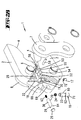
- Fig. 1 shows a pressing device 1 for pressing compacts 42 e.g. Sanitary fittings or the like.
- This pressing device 1 has two in the usual way Press lever 2, one end of which as press jaws 3 are trained. In the area of the press jaws 3 The press levers have 2 cam tracks on opposite ends 4 on, to be acted upon schematically shown rollers 5 of a press machine, not shown.
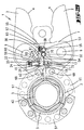
- the press levers arranged in this way 2 are interposed two, side by side at different distances from the press jaw 12 and covered by the connecting tabs 7, 8 to the outside Rolling body 52 rotatably connected to one another, for which purpose 2 recesses 54, 55 are formed in the press levers are in the course of closing the press lever 2 a space 56, 57 between the recesses 54, 55 and leave the rolling elements 52, 53. They are further Press lever 2 by means of one, also through the connecting straps 7, 8 covered compression spring 58 against each other acted upon in the closing direction.
- the press jaws 3 form a, in the closed position in Floor plan circular press jaw 12, each Press jaw 3 has a mouth opening that is semicircular in plan.
- the pressing device 1 For pressing a sanitary fitting onto one Pipe, the pressing device 1 is placed in such a way that the compact 42 is arranged in the region of the press jaw 12 is. By closing the press jaws 3 and thus of the press jaw 12, the desired press fit takes place.
- a monitoring device 13 monitors what a press lever 2 in Area of the upper, free mouth end 14 of the press jaw 3 a sensor 15 and this can be assigned to the other Press lever 2 in the area of its upper, free mouth end 16 has an adjustable stop 17.
- the stop 17 is seated in a threaded bore 18 of the Muzzle end 16 such that its body axis is approximately vertical to the associated end face 19 of the jaw end 16 is aligned. Furthermore, the arrangement is chosen so that the end interacting with the sensor 15 (stop tip 72) of the stop 17 over the end face 19 protrudes.
- the stop 17 is in the threaded bore for fine adjustment 20 adjustable, which setting is preferred by Screw displacement of the stop 17 by means of a the back of the screwdriver becomes.
- the found position of the stop 17 can then be fixed using grains, for example.
- the threaded bore 20 is, in particular for fine adjustment, formed as a through hole. To pollution to counteract the threaded bore 20 this preferably with a cap 21, for example sealed with a plastic cap.
- the sensor 15 is as one, in one to the end face 18 of a press lever 2 open bore 22 out Trigger pin 23 formed.
- the latter is heading in the direction onto the end face 18 by means of a compression spring 24, which is supported on one step of the bore 22 at one end, biased.
- This bore 25 is for connecting tabs 7, 8 opposite side formed open, also here to avoid contamination a cap 26, preferably a plastic cap can be placed.
- a central, stepped bore 27 having cover 28 screwed in.
- a locking pin passes through its bore 27 29, the upper free end in a trigger hole 30 of the free end of the trigger pin 23 is inserted.
- the bore 27 of the cap 26 is stepped molded.
- the free end of the locking pin 29th facing area is opposite the thick, free End enlarged area enlarged in diameter, whereby a locking step 32 forms.
- the Locking pin 29 provided with a plate 33, the outer diameter is chosen slightly smaller than the diameter the bore 25. Between this plate 33 and the this end face of the cover 28 is a the locking pin 29 comprising compression spring 34 is arranged to act on the locking pin 29 in the direction of the connecting straps 7, 8.
- the plate 33 On the side facing away from the spring 34 is the plate 33 provided with an application mandrel 35.
- An extension of the locking pin 29 is in the bore 25 a locking slide 36 mounted, but which one Tension spring 37, which at one end on the locking slide 36th and at the other end in the area of the loading mandrel 35 of the locking pin 29 is tied against the locking pin 29 biased.
- the end of the locking slide facing away from the locking pin 29 36 is provided with a locking pin 38 which is transverse is aligned to align the locking slide 36 and one open to a surface of the press lever 2 Recess 39 penetrating into a recess 40 an extension 41 of the connecting tab 7 engages.
- This recess 40 is on the press lever 2 facing Side of the connecting tab extension 41 formed and has according to the sectional views shown a backdrop-like contour.
- the locking pin 38 moves due to its relative displacement to the connecting tab 7 along one coaxial to the axis of rotation of the press lever 2 Circular section line in the recess 40, by running off a control edge 44 of the locking pin 38 on a control slope 45 of the recess 40 a Relocation of the locking slide 36 against the bias by the tension spring 37, this with simultaneous spring-assisted displacement of the locking pin 29 into a rest stop according to FIG. 6.
- the press levers 2 are in the complete closed position of the pressing jaws 3 according to FIG. 9, so acts on the stop 17 in the upper, free mouth end 16 of the other press lever 2 forming a sensor 15
- Trigger pin 23 by the over the end face 19 projecting head section of the stop 17 into the the trigger pin 23 leads bore 22 and here the trigger pin 23 against the bias the compression spring 24 shifted.
- This shift of the trigger pin 23 has a carry of the locking pin guided in the trigger hole 30 29 in a position coaxial to the cover bore 27.
- the reduced diameter Section of the bore 27 is the outer diameter of the adjusted thickened area of the locking pin 29, preferably slightly enlarged.
- the trigger pin 23 is not acted upon by the stop 17.
- the locking pin 29 remains in its locked position in the cover 28 respectively whose bore 27.
- the locking pin 38 in his, the blocking extension 46 rear blocking position.
- the press levers 2 preferably remain in here a partial opening position with an opening angle Alpha of approximately 10 °.
- the pressing device 1 can according to the Blocking cannot be removed from pellet 42. This can only be done after a complete pressing and an associated triggering of the blocking respectively.
- the monitoring device 13 can not only for simple press jaws with a fixed geometry be used, but also with locking jaws for locking chains - pressing tools and pressing jaws for interchangeable inserts.
- FIGS and 18 An exemplary embodiment of a pressing device with interchangeable inserts 48 is shown in FIGS and 18. These are supported by springs Locking elements 49 held on the press levers 2, which Locking by means of release pins 50 in a known manner Way can be canceled. Here is one, too trained and acting the first embodiment Monitoring device 13 is provided.
- FIG. 19 An exemplary embodiment of a locking chain press tool with a monitoring device according to the invention 13 is shown in FIG. 19.
- the DE-A1 198 03 536 referenced.
- the content of this patent application is hereby incorporated in full in the revelation present invention included, also to the Purposes, features of this patent application in claims to include the present invention.
- FIG. 1 Another exemplary embodiment of a pressing device - here with interchangeable inserts 48 - is 20 to 25.
- the closed position of the press jaws 3 or the press lever 2 by means of a monitoring device 13 monitors what a press lever 2 in the area of upper, free mouth end 14 of the press jaw 3 one Sensor 15 and this can be assigned to the other press lever 2 in the area of its upper, free mouth end 16 one adjustable stop 17 has.
- the sensor 15 is also in this embodiment designed as a mechanically acting release pin 23, the end facing the end face 18 like also the end of the stop interacting with this 17 projects beyond the respective end face 18, 19.
- the trigger pin 23 is in one of the end face 18 of the a lever 2 open bore 22 out and towards the end face 18, d. H. in sensor position, biased by a compression spring 24.
- the Displacement of the trigger pin 23 is limited by a stop pin arranged transversely to the bore 22 59, which is positioned accordingly Sheath recess 60 of the release pin 23 engages.
- This recess 60 is in the form of a flattening of the otherwise the trigger pin 23 is circular in cross section educated.
- the locking slide 36 guided in the bore 25 carries in the area of his, facing away from the trigger pin 23 End a locking pin 38 which is transverse to the alignment of the gate valve 36 is aligned and one too a surface of the press lever 2 open recess penetrating into a recess 40 of the connecting tab 7 engages.
- This recess 40 is also open the side facing the press lever 2 and has a in accordance with the sectional views shown Essentially L-backdrop-like contour.
- the locking slide 36 carrying the locking pin 38 is by means of a compression spring 63 in the direction of the trigger pin 23 biased.
- the one with the trigger pin 23 in the course of monitoring cooperating locking pin 29 is in this embodiment formed in one piece with the locking slide 36 and has at its free end one with the recess 62 of the release pin 23 cooperating latch 64 on, the end face 65 corresponding to the run-up slope 61 of the release pin 23 bevelled is.
- Monitoring device 13 The operation of that shown in Figs. 20 to 25 Monitoring device 13 is as follows:
- the release pin 23 is opposite the force of the compression spring 24 acting thereon by the stop acting on the release pin 23 17 crazy.
- this linear displacement of the release pin 23 runs the inclined end face 65 the locking part 29 along the ramp slope 61 what a relocation of the locking slide 36 against the Force of the compression spring 63 causes.
- the latch 64 falls Locking part 29 spring-supported by the compression spring 63 in the groove-shaped recess 62 of the release pin 23 a.
- self-retention is the in Fig. 24 shown position of trigger pin 23 and Locking slide 36 secured.
- This secured position is only in full Locking position of press jaws 3 reached.
- the one the locking slide 36 is arranged locking pin 38 by moving the locking slide 36 back into the Range of the substantially coaxial to the axis of rotation of the Press lever 2 aligned portion of the recess 40 proceed, with which the Press lever 2 fully back into its open position 21 can arrive.
- the locking is also in this embodiment between pivoting part (press lever 2) and the in contrast, non-rotatable part (recess 40) through the Connection tab 7 covered to the outside.
- an emergency release can also be provided be the opening of the pressing device 1, d. H. a pivoting of the press lever 2 in the open position allowed even after incomplete pressing.
- a separate handle 67 is provided, for example in the form a screwdriver or a hexagon wrench can be trained. By means of this handle 67 the stop 17 rearward to move the same in Direction applied to the trigger pin 23, so preferred screw-displaced in the direction of the release pin 23.
- FIG. 27 An alternative design of such an emergency release is shown in FIG. 27.
- a handle 67 assigned to the pressing device 1 is provided, which in extension of the locking slide 36 this is arranged and laterally over the end assigned press lever 2 for actuating the same protrudes.
- this handle 67 is for emergency release the locking slide 36 together with the locking pin 38 relocatable to the release position.
- the freely protruding handling end Position of the locking pin 38 recognizable, with what For example, application of signal colors in the penetration area the release and locking positions of the handle and press lever is readable.
- FIGS. 28 to 33 Another exemplary embodiment of a locking chain press tool with an inventive Monitoring device 13 is shown in FIGS. 28 to 33 shown.
- the sensor 15 is in the immediate vicinity Near the articulation points 68, 69 of the pressing members 51 to the Press levers 2 positioned.
- the monitoring device 13 also consists in this Embodiment essentially from a stop 17, a release pin 23 and a locking slide 36, a lock in the area of the roller body 52, 53 takes place. So this locking is also after covered on the outside by the connecting strap 7.
- the stop 17 sits in this embodiment in a threaded bore opening into the end face 19 18 one such that its body axis approximately aligned perpendicular to the associated end face 19 is. Furthermore, the arrangement is also selected here that the end of the cooperating with the sensor 15 Stop 17 extends beyond the end face 19.
- Trigger pin 23 is formed, which in the direction of the end face 18 is prestressed by means of a compression spring 24 is.
- the bore 22 is in this embodiment formed as a blind hole on the bottom the compression spring 24 for rearward loading the trigger pin 23 supports. The latter is heading in the direction limited to the end face 18 in its displacement through a arranged transversely to the bore 22 Auschlagit 59, which in a recess 60th otherwise essentially circular in cross-section Trigger pin 23 protrudes.
- This recess 60 of the release pin 23 forms his, the end face 18, d. H. the sensor area end facing a run-up slope 61, at which an annular groove forming a catch recess 62 connects. The latter is approximately half the extension the trigger pin 23 positioned.
- the bore 22 of the trigger pin 23 is crossed by a further bore 25 in which a gate valve 36 is linearly displaceable.
- the bore 25 is here approximately at the level of the recess 62 in the basic position of the Release pin 23 positioned according to FIG. 30 and makes an angle of approximately 90 ° with the bore 22 on.
- the bore 25 is to the articulation points 68, 69 of the Press lever 2 on the side facing open, a cap 26 to avoid contamination is attachable.
- the locking slide 36 is positioned in the bore 25 such that the trigger pin 23 crossing the bore 25 between the gate valve 36 and the one through which Cap 26 closed opening of the bore 25 is arranged is.
- the locking slide 36 is further by itself compression spring 63 in at the bottom of the bore 25 Directed to the trigger pin 23 and has in the roller body 53 facing away from the mouth Area adapted to the outer contour of the roller body 53 Recess 70, which in the open position according to Fig. 30 approximately covering the contour of the recess 55 of the Press lever 2 runs.
- the end of the locking slide facing the release pin 23 36 is integral with it to form one trained locking pin 29 beveled.
- the the resulting sloping face carries that Reference numeral 65.
- Monitoring device 13 The operation of that shown in Figs. 28 to 33 Monitoring device 13 is as follows:
- the trigger pin 23 is in the stroke-limited, spring-assisted Basic position in which this with its free end over the end face 18 of the rotary lever 2 protrudes.
- the compression spring 63 causes a shift of the locking slide 36 in the direction of the trigger pin 23, after which the locking pin 29, tip resulting from the oblique face 65 the recess 60 of the release pin 23 enters.
- In 31 is the tip region the inclined end face 65 on the ramp slope 61 of the recess 60.
- the locking pin 38 is now in the area of the apex of the rolling body 53, which is a rotational displacement of the Press lever 2 into the open position by supporting it the locking pin 38 prevented on the roller body 52.
- the locking pin 38 is closed, in particular from FIG. 31 recognize in the between the recess 55 of the press lever 2 and the roller body 53 formed free space 57 retracted.
- the press lever preferably remains 2 in a partially open position with an opening angle Alpha of approximately 10 °.
- the pressing device 1 can not removed from the compact due to blocking become. However, it is also an emergency release here as in the previously described embodiments conceivable.
- the locking or the release the press lever 2 causing displaceable pins and slider are integrated in a press lever 2.
- the monitoring device 13 opposite the outer surface of the press lever 2 is sunk or arranged flat. This also applies to the sensor 15 and the stop 17, optionally with Except for those that are outstanding over the end faces 18 and 19 Sensor tip 71 or stop surface 72.
- a pressing device in which the monitoring device 13 as a whole is arranged inside a press lever 2.
- a pressing device in which the monitoring device 13 opposite the outer surface of the press lever 2 sunk or is arranged plan.
- a pressing device in which the sensor 15, optionally with Exception of a sensor tip 71, inside a press lever 2 is arranged.
- a pressing device in which the sensor 15 opposite the outer surface of the press lever 2 is sunk or arranged flat.
- Object of the invention alone or combined with one of the above described items from Is important, especially in combination with one of the claims of the application is a pressing device, in which the sensor 15 is incomplete Pressing a mechanical blockage between the Connecting tab 7 and the one press lever 2 triggers.
- a pressing device in which in a press lever 2 a locking slide 36 is arranged, with a, in a recess 40 of the connecting tab 7 protruding locking pin 38 and in which the locking pin 38 is incomplete Compression against a blocking extension 46 runs in the recess 40 of the connecting tab 7.
- Object of the invention alone or combined with one of the above described items from Is important, especially in combination with one of the claims of the application is a pressing device, in which the locking slide 36 under tension is in the locked position of the locking pin 38, what preload only with complete pressing can be canceled.
- a pressing device in which the locking slide 36 by a Locking pin 29 is applied, the locking slide 36th when fully pressed into the release position shifted.
- Object of the invention alone or combined with one of the above described items from Is important, especially in combination with one of the claims of the application is a pressing device, in which the locking pin 29 in the release position the locking slide 36 is biased and the Preload released with complete pressing becomes.
- a pressing device in which the locking pin 29 from a trigger pin 23 into a blocking position which inhibits the preload is acted upon and when the trigger pin is acted upon 23 by the other press lever 2 the bias to move the locking slide 36 in the Release position is released.
- a pressing device which one in the other press lever 2 adjustable stop 17 for the trigger pin 23 is arranged is.
- Object of the invention alone or combined with one of the above described items from Is important, especially in combination with one of the claims of the application is a pressing device, in which the locking pin 29 with the locking slide 36 is formed in one piece.
- Object of the invention alone or combined with one of the above described items from Is important, especially in combination with one of the claims of the application is a pressing device, in which the trigger pin 23 a the locking pin 29 assigned casserole 61 has to Displacement of the locking pin 29 or the locking slide 36 in the release position in the course of pressing.
- Object of the invention alone or combined with one of the above described items from Is important, especially in combination with one of the claims of the application is a pressing device, in which the locking pin 29 after a displacement in the release position in a locking recess 62 of the trigger pin 23 engages.
- Object of the invention alone or combined with one of the above described items from Is important, especially in combination with one of the claims of the application is a pressing device, in which the trigger pin 23 in a sensor position is biased.
- Object of the invention alone or combined with one of the above described items from Is important, especially in combination with one of the claims of the application is a pressing device, in which when moving the press lever 2 both the trigger pin 23 and the stop 17 on the assigned end face 18, 19 of the press lever 2 protrude.
- Object of the invention alone or combined with one of the above described items from Is important, especially in combination with one of the claims of the application is a pressing device, at which the angle to the locking pin 38 triggerable trigger pin 23 has a run-up slope 61, the locking pin when fully pressed 38 moved into the release position.
- Object of the invention alone or combined with one of the above described items from Is important, especially in combination with one of the claims of the application is a pressing device, in which the locking bracket of the locking pin 38 is lifted in the course of the opening movement.
- Object of the invention alone or combined with one of the above described items from Is important, especially in combination with one of the claims of the application is a pressing device, in which the mechanical locking by one in one facing the press lever 2 Recess 40 created on the side of the connecting tab 7 protruding and guided in the press lever 2 locking pin 38 is reached.
- a pressing device in which assigned in the press levers 2 Recesses 54, 55 are formed for the rolling bodies 52, 53 are in the course of closing the press lever 2 a free space 56, 57 between a recess 54, 55 and the roller body 52, 53 and in which the locking pin 38 retracted into this free space 56, 57 only in the course of a complete pressing Movement of the trigger pin 23 in the release position is movable.
- a pressing device in which two rolling elements 52, 53 with associated Recesses 54, 55 in the press levers 2 side by side at different distances from the press jaw 12 are arranged.
- Object of the invention alone or combined with one of the above described items from Is important, especially in combination with one of the claims of the application is a pressing device, in which the locking pin 38 with the remainder of the mouth Rolling body 53 cooperates.
- Object of the invention alone or combined with one of the above described items from Is important, especially in combination with one of the claims of the application is a pressing device, in which after an incomplete pressing the release position of the locking device 38 by an emergency release can be reached.
- a pressing device in which a handle 67 for emergency release the trigger pin 23 or the stop 17 or the locking pin 38 is assignable.
- a pressing device in which the handle 67 as an extension of the Lock pin 38 and the locking slide 36 is formed and to pull or push the locking pin 38 or locking slide 36 in the release position laterally but the press lever 2 protrudes.
Landscapes
- Engineering & Computer Science (AREA)
- Mechanical Engineering (AREA)
- Hand Tools For Fitting Together And Separating, Or Other Hand Tools (AREA)
- Manipulator (AREA)
- Press Drives And Press Lines (AREA)
Applications Claiming Priority (4)
| Application Number | Priority Date | Filing Date | Title |
|---|---|---|---|
| DE19949703 | 1999-10-15 | ||
| DE19949703 | 1999-10-15 | ||
| DE10010601A DE10010601A1 (de) | 1999-10-15 | 2000-03-03 | Verpreßgerät mit Preßbacken |
| DE10010601 | 2000-03-03 |
Publications (2)
| Publication Number | Publication Date |
|---|---|
| EP1092487A2 true EP1092487A2 (fr) | 2001-04-18 |
| EP1092487A3 EP1092487A3 (fr) | 2004-08-25 |
Family
ID=26004688
Family Applications (1)
| Application Number | Title | Priority Date | Filing Date |
|---|---|---|---|
| EP00119451A Withdrawn EP1092487A3 (fr) | 1999-10-15 | 2000-09-14 | Dispositif de pressage avec machoires de compression |
Country Status (2)
| Country | Link |
|---|---|
| US (1) | US6457338B1 (fr) |
| EP (1) | EP1092487A3 (fr) |
Cited By (8)
| Publication number | Priority date | Publication date | Assignee | Title |
|---|---|---|---|---|
| EP1114698A2 (fr) * | 2000-01-07 | 2001-07-11 | Von Arx Ag | Pince à sertir |
| US7059166B2 (en) | 2002-06-17 | 2006-06-13 | Emerson Electric Co. | Method and apparatus for assuring or determining appropriate closure of a crimp assembly |
| US7155955B2 (en) | 2001-09-11 | 2007-01-02 | Emerson Electric Co. | Crimping assembly |
| WO2008138987A2 (fr) | 2007-05-16 | 2008-11-20 | Gustav Klauke Gmbh | Procédé de fonctionnement d'un appareil de compression à main motorisé et appareil de compression à main |
| EP2796245A1 (fr) | 2013-04-23 | 2014-10-29 | Geberit International AG | Outil de presse |
| EP3231528A1 (fr) * | 2016-04-12 | 2017-10-18 | Geberit International AG | Dispositif de pression comprenant une fixation a boulon |
| EP3246130A1 (fr) * | 2016-05-19 | 2017-11-22 | Geberit International AG | Dispositif de presse |
| EP3610988A1 (fr) | 2018-08-17 | 2020-02-19 | Geberit International AG | Dispositif de pression à fixation à boulon centrée |
Families Citing this family (339)
| Publication number | Priority date | Publication date | Assignee | Title |
|---|---|---|---|---|
| US6629975B1 (en) * | 1999-12-20 | 2003-10-07 | Pioneer Laboratories, Icn. | Multiple lumen crimp |
| DE10051010A1 (de) * | 2000-10-14 | 2002-04-18 | Klauke Gmbh Gustav | Kraftmesswerkzeug |
| WO2003049883A1 (fr) * | 2001-12-08 | 2003-06-19 | Gustav Klauke Gmbh | Dispositif de compression |
| WO2004078398A1 (fr) * | 2003-03-06 | 2004-09-16 | Von Arx Ag | Appareil de pressage |
| US20070084897A1 (en) | 2003-05-20 | 2007-04-19 | Shelton Frederick E Iv | Articulating surgical stapling instrument incorporating a two-piece e-beam firing mechanism |
| US9060770B2 (en) | 2003-05-20 | 2015-06-23 | Ethicon Endo-Surgery, Inc. | Robotically-driven surgical instrument with E-beam driver |
| WO2005049280A1 (fr) * | 2003-11-20 | 2005-06-02 | Von Arx Ag | Unite de porte-cylindres |
| US6996913B2 (en) * | 2004-01-29 | 2006-02-14 | The Boeing Company | Circumferential measurement of tubular members |
| US20080016939A1 (en) * | 2004-07-02 | 2008-01-24 | Egbert Frenken | Pair of pressing jaws for hydraulic or electric pressing tools |
| US7216523B2 (en) * | 2004-07-02 | 2007-05-15 | Gustav Klauke Gmbh | Pair of pressing jaws for hydraulic or electric pressing tools, and insulating covering for a pressing jaw |
| DE202006013693U1 (de) * | 2006-09-07 | 2008-01-17 | Gustav Klauke Gmbh | Pressbackenpaar für hydraulische oder elektrische Verpressgeräte |
| US8215531B2 (en) | 2004-07-28 | 2012-07-10 | Ethicon Endo-Surgery, Inc. | Surgical stapling instrument having a medical substance dispenser |
| US11890012B2 (en) | 2004-07-28 | 2024-02-06 | Cilag Gmbh International | Staple cartridge comprising cartridge body and attached support |
| WO2006050377A2 (fr) * | 2004-11-01 | 2006-05-11 | Superior Tool Corporation | Dispositifs portatifs |
| US7464578B2 (en) | 2005-06-03 | 2008-12-16 | Fci Americas Technology, Inc. | Hand-held, portable, battery-powered hydraulic tool |
| DE102005026219B4 (de) * | 2005-06-07 | 2007-12-13 | Poly-Clip System Gmbh & Co. Kg | Clipmaschine und Verfahren zum Einrichten einer Clipmaschine |
| EP1910035B1 (fr) * | 2005-07-19 | 2011-10-19 | Autocondizionatori Zani S.R.L. | Outil conçu pour le raccordement de tubes au moyen de manchons de raccordement |
| US11246590B2 (en) | 2005-08-31 | 2022-02-15 | Cilag Gmbh International | Staple cartridge including staple drivers having different unfired heights |
| US11484312B2 (en) | 2005-08-31 | 2022-11-01 | Cilag Gmbh International | Staple cartridge comprising a staple driver arrangement |
| US7934630B2 (en) | 2005-08-31 | 2011-05-03 | Ethicon Endo-Surgery, Inc. | Staple cartridges for forming staples having differing formed staple heights |
| US9237891B2 (en) | 2005-08-31 | 2016-01-19 | Ethicon Endo-Surgery, Inc. | Robotically-controlled surgical stapling devices that produce formed staples having different lengths |
| US10159482B2 (en) | 2005-08-31 | 2018-12-25 | Ethicon Llc | Fastener cartridge assembly comprising a fixed anvil and different staple heights |
| US7669746B2 (en) | 2005-08-31 | 2010-03-02 | Ethicon Endo-Surgery, Inc. | Staple cartridges for forming staples having differing formed staple heights |
| US20070106317A1 (en) | 2005-11-09 | 2007-05-10 | Shelton Frederick E Iv | Hydraulically and electrically actuated articulation joints for surgical instruments |
| US20110024477A1 (en) | 2009-02-06 | 2011-02-03 | Hall Steven G | Driven Surgical Stapler Improvements |
| US8708213B2 (en) | 2006-01-31 | 2014-04-29 | Ethicon Endo-Surgery, Inc. | Surgical instrument having a feedback system |
| US11278279B2 (en) | 2006-01-31 | 2022-03-22 | Cilag Gmbh International | Surgical instrument assembly |
| US7753904B2 (en) | 2006-01-31 | 2010-07-13 | Ethicon Endo-Surgery, Inc. | Endoscopic surgical instrument with a handle that can articulate with respect to the shaft |
| US20120292367A1 (en) | 2006-01-31 | 2012-11-22 | Ethicon Endo-Surgery, Inc. | Robotically-controlled end effector |
| US8186555B2 (en) | 2006-01-31 | 2012-05-29 | Ethicon Endo-Surgery, Inc. | Motor-driven surgical cutting and fastening instrument with mechanical closure system |
| US7845537B2 (en) | 2006-01-31 | 2010-12-07 | Ethicon Endo-Surgery, Inc. | Surgical instrument having recording capabilities |
| US11793518B2 (en) | 2006-01-31 | 2023-10-24 | Cilag Gmbh International | Powered surgical instruments with firing system lockout arrangements |
| US20110290856A1 (en) | 2006-01-31 | 2011-12-01 | Ethicon Endo-Surgery, Inc. | Robotically-controlled surgical instrument with force-feedback capabilities |
| US8820603B2 (en) | 2006-01-31 | 2014-09-02 | Ethicon Endo-Surgery, Inc. | Accessing data stored in a memory of a surgical instrument |
| US11224427B2 (en) | 2006-01-31 | 2022-01-18 | Cilag Gmbh International | Surgical stapling system including a console and retraction assembly |
| US8992422B2 (en) | 2006-03-23 | 2015-03-31 | Ethicon Endo-Surgery, Inc. | Robotically-controlled endoscopic accessory channel |
| US8322455B2 (en) | 2006-06-27 | 2012-12-04 | Ethicon Endo-Surgery, Inc. | Manually driven surgical cutting and fastening instrument |
| US10568652B2 (en) | 2006-09-29 | 2020-02-25 | Ethicon Llc | Surgical staples having attached drivers of different heights and stapling instruments for deploying the same |
| US11980366B2 (en) | 2006-10-03 | 2024-05-14 | Cilag Gmbh International | Surgical instrument |
| US8652120B2 (en) | 2007-01-10 | 2014-02-18 | Ethicon Endo-Surgery, Inc. | Surgical instrument with wireless communication between control unit and sensor transponders |
| US11291441B2 (en) | 2007-01-10 | 2022-04-05 | Cilag Gmbh International | Surgical instrument with wireless communication between control unit and remote sensor |
| US8684253B2 (en) | 2007-01-10 | 2014-04-01 | Ethicon Endo-Surgery, Inc. | Surgical instrument with wireless communication between a control unit of a robotic system and remote sensor |
| US11039836B2 (en) | 2007-01-11 | 2021-06-22 | Cilag Gmbh International | Staple cartridge for use with a surgical stapling instrument |
| US8540128B2 (en) | 2007-01-11 | 2013-09-24 | Ethicon Endo-Surgery, Inc. | Surgical stapling device with a curved end effector |
| US7669747B2 (en) | 2007-03-15 | 2010-03-02 | Ethicon Endo-Surgery, Inc. | Washer for use with a surgical stapling instrument |
| US20080282762A1 (en) * | 2007-05-18 | 2008-11-20 | Fci Americas Technology, Inc. | Tool with connector locator |
| US20080289394A1 (en) * | 2007-05-23 | 2008-11-27 | Emerson Electric Co. | Compression jaw set with failure mode preventing reuse |
| US8931682B2 (en) | 2007-06-04 | 2015-01-13 | Ethicon Endo-Surgery, Inc. | Robotically-controlled shaft based rotary drive systems for surgical instruments |
| US11857181B2 (en) | 2007-06-04 | 2024-01-02 | Cilag Gmbh International | Robotically-controlled shaft based rotary drive systems for surgical instruments |
| US7753245B2 (en) | 2007-06-22 | 2010-07-13 | Ethicon Endo-Surgery, Inc. | Surgical stapling instruments |
| US11849941B2 (en) | 2007-06-29 | 2023-12-26 | Cilag Gmbh International | Staple cartridge having staple cavities extending at a transverse angle relative to a longitudinal cartridge axis |
| US7819298B2 (en) | 2008-02-14 | 2010-10-26 | Ethicon Endo-Surgery, Inc. | Surgical stapling apparatus with control features operable with one hand |
| US7866527B2 (en) | 2008-02-14 | 2011-01-11 | Ethicon Endo-Surgery, Inc. | Surgical stapling apparatus with interlockable firing system |
| BRPI0901282A2 (pt) | 2008-02-14 | 2009-11-17 | Ethicon Endo Surgery Inc | instrumento cirúrgico de corte e fixação dotado de eletrodos de rf |
| US11986183B2 (en) | 2008-02-14 | 2024-05-21 | Cilag Gmbh International | Surgical cutting and fastening instrument comprising a plurality of sensors to measure an electrical parameter |
| US9179912B2 (en) | 2008-02-14 | 2015-11-10 | Ethicon Endo-Surgery, Inc. | Robotically-controlled motorized surgical cutting and fastening instrument |
| US8636736B2 (en) | 2008-02-14 | 2014-01-28 | Ethicon Endo-Surgery, Inc. | Motorized surgical cutting and fastening instrument |
| US9770245B2 (en) | 2008-02-15 | 2017-09-26 | Ethicon Llc | Layer arrangements for surgical staple cartridges |
| US10136890B2 (en) | 2010-09-30 | 2018-11-27 | Ethicon Llc | Staple cartridge comprising a variable thickness compressible portion |
| US9386983B2 (en) | 2008-09-23 | 2016-07-12 | Ethicon Endo-Surgery, Llc | Robotically-controlled motorized surgical instrument |
| US8210411B2 (en) | 2008-09-23 | 2012-07-03 | Ethicon Endo-Surgery, Inc. | Motor-driven surgical cutting instrument |
| US11648005B2 (en) | 2008-09-23 | 2023-05-16 | Cilag Gmbh International | Robotically-controlled motorized surgical instrument with an end effector |
| US9005230B2 (en) | 2008-09-23 | 2015-04-14 | Ethicon Endo-Surgery, Inc. | Motorized surgical instrument |
| US8608045B2 (en) | 2008-10-10 | 2013-12-17 | Ethicon Endo-Sugery, Inc. | Powered surgical cutting and stapling apparatus with manually retractable firing system |
| US8517239B2 (en) | 2009-02-05 | 2013-08-27 | Ethicon Endo-Surgery, Inc. | Surgical stapling instrument comprising a magnetic element driver |
| WO2010090940A1 (fr) | 2009-02-06 | 2010-08-12 | Ethicon Endo-Surgery, Inc. | Améliorations d'agrafeuse chirurgicale commandée |
| US20100253066A1 (en) * | 2009-04-02 | 2010-10-07 | Victaulic Company | Crimp-Type Coupling, Crimping Tool and Method of Crimping |
| US8851354B2 (en) | 2009-12-24 | 2014-10-07 | Ethicon Endo-Surgery, Inc. | Surgical cutting instrument that analyzes tissue thickness |
| US8783543B2 (en) | 2010-07-30 | 2014-07-22 | Ethicon Endo-Surgery, Inc. | Tissue acquisition arrangements and methods for surgical stapling devices |
| US11812965B2 (en) | 2010-09-30 | 2023-11-14 | Cilag Gmbh International | Layer of material for a surgical end effector |
| US9211120B2 (en) | 2011-04-29 | 2015-12-15 | Ethicon Endo-Surgery, Inc. | Tissue thickness compensator comprising a plurality of medicaments |
| US9320523B2 (en) | 2012-03-28 | 2016-04-26 | Ethicon Endo-Surgery, Llc | Tissue thickness compensator comprising tissue ingrowth features |
| US11298125B2 (en) | 2010-09-30 | 2022-04-12 | Cilag Gmbh International | Tissue stapler having a thickness compensator |
| US9788834B2 (en) | 2010-09-30 | 2017-10-17 | Ethicon Llc | Layer comprising deployable attachment members |
| US10945731B2 (en) | 2010-09-30 | 2021-03-16 | Ethicon Llc | Tissue thickness compensator comprising controlled release and expansion |
| US9629814B2 (en) | 2010-09-30 | 2017-04-25 | Ethicon Endo-Surgery, Llc | Tissue thickness compensator configured to redistribute compressive forces |
| US11925354B2 (en) | 2010-09-30 | 2024-03-12 | Cilag Gmbh International | Staple cartridge comprising staples positioned within a compressible portion thereof |
| US8695866B2 (en) | 2010-10-01 | 2014-04-15 | Ethicon Endo-Surgery, Inc. | Surgical instrument having a power control circuit |
| CN201940910U (zh) * | 2010-11-18 | 2011-08-24 | 润联(天津)五金工具有限公司 | 用于卡箍和卡环的钳头 |
| JP6026509B2 (ja) | 2011-04-29 | 2016-11-16 | エシコン・エンド−サージェリィ・インコーポレイテッドEthicon Endo−Surgery,Inc. | ステープルカートリッジ自体の圧縮可能部分内に配置されたステープルを含むステープルカートリッジ |
| US11207064B2 (en) | 2011-05-27 | 2021-12-28 | Cilag Gmbh International | Automated end effector component reloading system for use with a robotic system |
| US9072535B2 (en) | 2011-05-27 | 2015-07-07 | Ethicon Endo-Surgery, Inc. | Surgical stapling instruments with rotatable staple deployment arrangements |
| CN102226362A (zh) * | 2011-05-27 | 2011-10-26 | 伟速达(福州)安全系统有限公司 | 车辆转向柱锁 |
| US9463556B2 (en) | 2012-03-13 | 2016-10-11 | Hubbell Incorporated | Crimp tool force monitoring device |
| MX350846B (es) | 2012-03-28 | 2017-09-22 | Ethicon Endo Surgery Inc | Compensador de grosor de tejido que comprende cápsulas que definen un ambiente de baja presión. |
| JP6224070B2 (ja) | 2012-03-28 | 2017-11-01 | エシコン・エンド−サージェリィ・インコーポレイテッドEthicon Endo−Surgery,Inc. | 組織厚さコンペンセータを含む保持具アセンブリ |
| JP6305979B2 (ja) | 2012-03-28 | 2018-04-04 | エシコン・エンド−サージェリィ・インコーポレイテッドEthicon Endo−Surgery,Inc. | 複数の層を含む組織厚さコンペンセーター |
| US9101358B2 (en) | 2012-06-15 | 2015-08-11 | Ethicon Endo-Surgery, Inc. | Articulatable surgical instrument comprising a firing drive |
| US20140001231A1 (en) | 2012-06-28 | 2014-01-02 | Ethicon Endo-Surgery, Inc. | Firing system lockout arrangements for surgical instruments |
| US9282974B2 (en) | 2012-06-28 | 2016-03-15 | Ethicon Endo-Surgery, Llc | Empty clip cartridge lockout |
| US11278284B2 (en) | 2012-06-28 | 2022-03-22 | Cilag Gmbh International | Rotary drive arrangements for surgical instruments |
| BR112014032740A2 (pt) | 2012-06-28 | 2020-02-27 | Ethicon Endo Surgery Inc | bloqueio de cartucho de clipes vazio |
| US9408606B2 (en) | 2012-06-28 | 2016-08-09 | Ethicon Endo-Surgery, Llc | Robotically powered surgical device with manually-actuatable reversing system |
| BR112014032776B1 (pt) | 2012-06-28 | 2021-09-08 | Ethicon Endo-Surgery, Inc | Sistema de instrumento cirúrgico e kit cirúrgico para uso com um sistema de instrumento cirúrgico |
| US9289256B2 (en) | 2012-06-28 | 2016-03-22 | Ethicon Endo-Surgery, Llc | Surgical end effectors having angled tissue-contacting surfaces |
| MX364729B (es) | 2013-03-01 | 2019-05-06 | Ethicon Endo Surgery Inc | Instrumento quirúrgico con una parada suave. |
| RU2672520C2 (ru) | 2013-03-01 | 2018-11-15 | Этикон Эндо-Серджери, Инк. | Шарнирно поворачиваемые хирургические инструменты с проводящими путями для передачи сигналов |
| US9629629B2 (en) | 2013-03-14 | 2017-04-25 | Ethicon Endo-Surgey, LLC | Control systems for surgical instruments |
| US9388885B2 (en) | 2013-03-15 | 2016-07-12 | Ideal Industries, Inc. | Multi-tool transmission and attachments for rotary tool |
| US10149680B2 (en) | 2013-04-16 | 2018-12-11 | Ethicon Llc | Surgical instrument comprising a gap setting system |
| BR112015026109B1 (pt) | 2013-04-16 | 2022-02-22 | Ethicon Endo-Surgery, Inc | Instrumento cirúrgico |
| US20150053743A1 (en) | 2013-08-23 | 2015-02-26 | Ethicon Endo-Surgery, Inc. | Error detection arrangements for surgical instrument assemblies |
| BR112016003329B1 (pt) | 2013-08-23 | 2021-12-21 | Ethicon Endo-Surgery, Llc | Instrumento cirúrgico |
| DE102013112848B3 (de) * | 2013-11-21 | 2015-04-23 | Viega Gmbh & Co. Kg | Presswerkzeug mit bistabilem Spannungsmechanismus |
| US9826977B2 (en) | 2014-03-26 | 2017-11-28 | Ethicon Llc | Sterilization verification circuit |
| BR112016021943B1 (pt) | 2014-03-26 | 2022-06-14 | Ethicon Endo-Surgery, Llc | Instrumento cirúrgico para uso por um operador em um procedimento cirúrgico |
| BR112016023825B1 (pt) | 2014-04-16 | 2022-08-02 | Ethicon Endo-Surgery, Llc | Cartucho de grampos para uso com um grampeador cirúrgico e cartucho de grampos para uso com um instrumento cirúrgico |
| US20150297225A1 (en) | 2014-04-16 | 2015-10-22 | Ethicon Endo-Surgery, Inc. | Fastener cartridges including extensions having different configurations |
| CN106456159B (zh) | 2014-04-16 | 2019-03-08 | 伊西康内外科有限责任公司 | 紧固件仓组件和钉保持器盖布置结构 |
| CN106456176B (zh) | 2014-04-16 | 2019-06-28 | 伊西康内外科有限责任公司 | 包括具有不同构型的延伸部的紧固件仓 |
| CN111451998A (zh) | 2014-07-07 | 2020-07-28 | 塞母布雷有限公司 | 流体动力压缩或切割工具和致动流体动力压缩工具的方法 |
| US11311294B2 (en) | 2014-09-05 | 2022-04-26 | Cilag Gmbh International | Powered medical device including measurement of closure state of jaws |
| US9724094B2 (en) | 2014-09-05 | 2017-08-08 | Ethicon Llc | Adjunct with integrated sensors to quantify tissue compression |
| BR112017004361B1 (pt) | 2014-09-05 | 2023-04-11 | Ethicon Llc | Sistema eletrônico para um instrumento cirúrgico |
| DE102014112869B3 (de) * | 2014-09-08 | 2016-01-07 | Viega Gmbh & Co. Kg | Presswerkzeug mit zuschaltbarem bistabilen Spannmechanismus |
| US10105142B2 (en) | 2014-09-18 | 2018-10-23 | Ethicon Llc | Surgical stapler with plurality of cutting elements |
| JP6648119B2 (ja) | 2014-09-26 | 2020-02-14 | エシコン エルエルシーEthicon LLC | 外科ステープル留めバットレス及び付属物材料 |
| US11523821B2 (en) | 2014-09-26 | 2022-12-13 | Cilag Gmbh International | Method for creating a flexible staple line |
| US9924944B2 (en) | 2014-10-16 | 2018-03-27 | Ethicon Llc | Staple cartridge comprising an adjunct material |
| US11141153B2 (en) | 2014-10-29 | 2021-10-12 | Cilag Gmbh International | Staple cartridges comprising driver arrangements |
| US10517594B2 (en) | 2014-10-29 | 2019-12-31 | Ethicon Llc | Cartridge assemblies for surgical staplers |
| US9844376B2 (en) | 2014-11-06 | 2017-12-19 | Ethicon Llc | Staple cartridge comprising a releasable adjunct material |
| US10736636B2 (en) | 2014-12-10 | 2020-08-11 | Ethicon Llc | Articulatable surgical instrument system |
| US9987000B2 (en) | 2014-12-18 | 2018-06-05 | Ethicon Llc | Surgical instrument assembly comprising a flexible articulation system |
| US9844374B2 (en) | 2014-12-18 | 2017-12-19 | Ethicon Llc | Surgical instrument systems comprising an articulatable end effector and means for adjusting the firing stroke of a firing member |
| US10245027B2 (en) | 2014-12-18 | 2019-04-02 | Ethicon Llc | Surgical instrument with an anvil that is selectively movable about a discrete non-movable axis relative to a staple cartridge |
| US10085748B2 (en) | 2014-12-18 | 2018-10-02 | Ethicon Llc | Locking arrangements for detachable shaft assemblies with articulatable surgical end effectors |
| US9844375B2 (en) | 2014-12-18 | 2017-12-19 | Ethicon Llc | Drive arrangements for articulatable surgical instruments |
| BR112017012996B1 (pt) | 2014-12-18 | 2022-11-08 | Ethicon Llc | Instrumento cirúrgico com uma bigorna que é seletivamente móvel sobre um eixo geométrico imóvel distinto em relação a um cartucho de grampos |
| US11154301B2 (en) | 2015-02-27 | 2021-10-26 | Cilag Gmbh International | Modular stapling assembly |
| JP2020121162A (ja) | 2015-03-06 | 2020-08-13 | エシコン エルエルシーEthicon LLC | 測定の安定性要素、クリープ要素、及び粘弾性要素を決定するためのセンサデータの時間依存性評価 |
| US10245033B2 (en) | 2015-03-06 | 2019-04-02 | Ethicon Llc | Surgical instrument comprising a lockable battery housing |
| US10052044B2 (en) | 2015-03-06 | 2018-08-21 | Ethicon Llc | Time dependent evaluation of sensor data to determine stability, creep, and viscoelastic elements of measures |
| US9993248B2 (en) | 2015-03-06 | 2018-06-12 | Ethicon Endo-Surgery, Llc | Smart sensors with local signal processing |
| US10441279B2 (en) | 2015-03-06 | 2019-10-15 | Ethicon Llc | Multiple level thresholds to modify operation of powered surgical instruments |
| US10390825B2 (en) | 2015-03-31 | 2019-08-27 | Ethicon Llc | Surgical instrument with progressive rotary drive systems |
| US10105139B2 (en) | 2015-09-23 | 2018-10-23 | Ethicon Llc | Surgical stapler having downstream current-based motor control |
| US10238386B2 (en) | 2015-09-23 | 2019-03-26 | Ethicon Llc | Surgical stapler having motor control based on an electrical parameter related to a motor current |
| US10299878B2 (en) | 2015-09-25 | 2019-05-28 | Ethicon Llc | Implantable adjunct systems for determining adjunct skew |
| US11690623B2 (en) | 2015-09-30 | 2023-07-04 | Cilag Gmbh International | Method for applying an implantable layer to a fastener cartridge |
| US10980539B2 (en) | 2015-09-30 | 2021-04-20 | Ethicon Llc | Implantable adjunct comprising bonded layers |
| US11890015B2 (en) | 2015-09-30 | 2024-02-06 | Cilag Gmbh International | Compressible adjunct with crossing spacer fibers |
| US10736633B2 (en) | 2015-09-30 | 2020-08-11 | Ethicon Llc | Compressible adjunct with looping members |
| USD796927S1 (en) * | 2015-11-13 | 2017-09-12 | Gustav Klauke Gmbh | Crimping tool |
| US10368865B2 (en) | 2015-12-30 | 2019-08-06 | Ethicon Llc | Mechanisms for compensating for drivetrain failure in powered surgical instruments |
| US10265068B2 (en) | 2015-12-30 | 2019-04-23 | Ethicon Llc | Surgical instruments with separable motors and motor control circuits |
| US10292704B2 (en) | 2015-12-30 | 2019-05-21 | Ethicon Llc | Mechanisms for compensating for battery pack failure in powered surgical instruments |
| US11213293B2 (en) | 2016-02-09 | 2022-01-04 | Cilag Gmbh International | Articulatable surgical instruments with single articulation link arrangements |
| JP6911054B2 (ja) | 2016-02-09 | 2021-07-28 | エシコン エルエルシーEthicon LLC | 非対称の関節構成を備えた外科用器具 |
| US11224426B2 (en) | 2016-02-12 | 2022-01-18 | Cilag Gmbh International | Mechanisms for compensating for drivetrain failure in powered surgical instruments |
| US10448948B2 (en) | 2016-02-12 | 2019-10-22 | Ethicon Llc | Mechanisms for compensating for drivetrain failure in powered surgical instruments |
| US10426467B2 (en) | 2016-04-15 | 2019-10-01 | Ethicon Llc | Surgical instrument with detection sensors |
| US10357247B2 (en) | 2016-04-15 | 2019-07-23 | Ethicon Llc | Surgical instrument with multiple program responses during a firing motion |
| US10335145B2 (en) | 2016-04-15 | 2019-07-02 | Ethicon Llc | Modular surgical instrument with configurable operating mode |
| US10456137B2 (en) | 2016-04-15 | 2019-10-29 | Ethicon Llc | Staple formation detection mechanisms |
| US10828028B2 (en) | 2016-04-15 | 2020-11-10 | Ethicon Llc | Surgical instrument with multiple program responses during a firing motion |
| US11179150B2 (en) | 2016-04-15 | 2021-11-23 | Cilag Gmbh International | Systems and methods for controlling a surgical stapling and cutting instrument |
| US10492783B2 (en) | 2016-04-15 | 2019-12-03 | Ethicon, Llc | Surgical instrument with improved stop/start control during a firing motion |
| US11607239B2 (en) | 2016-04-15 | 2023-03-21 | Cilag Gmbh International | Systems and methods for controlling a surgical stapling and cutting instrument |
| US10363037B2 (en) | 2016-04-18 | 2019-07-30 | Ethicon Llc | Surgical instrument system comprising a magnetic lockout |
| US11317917B2 (en) | 2016-04-18 | 2022-05-03 | Cilag Gmbh International | Surgical stapling system comprising a lockable firing assembly |
| US20170296173A1 (en) | 2016-04-18 | 2017-10-19 | Ethicon Endo-Surgery, Llc | Method for operating a surgical instrument |
| WO2018064671A1 (fr) | 2016-09-30 | 2018-04-05 | Milwaukee Electric Tool Corporation | Outil électrique |
| US20180168625A1 (en) | 2016-12-21 | 2018-06-21 | Ethicon Endo-Surgery, Llc | Surgical stapling instruments with smart staple cartridges |
| US10980536B2 (en) | 2016-12-21 | 2021-04-20 | Ethicon Llc | No-cartridge and spent cartridge lockout arrangements for surgical staplers |
| JP7010956B2 (ja) | 2016-12-21 | 2022-01-26 | エシコン エルエルシー | 組織をステープル留めする方法 |
| US10918385B2 (en) | 2016-12-21 | 2021-02-16 | Ethicon Llc | Surgical system comprising a firing member rotatable into an articulation state to articulate an end effector of the surgical system |
| US10568626B2 (en) | 2016-12-21 | 2020-02-25 | Ethicon Llc | Surgical instruments with jaw opening features for increasing a jaw opening distance |
| CN110087565A (zh) | 2016-12-21 | 2019-08-02 | 爱惜康有限责任公司 | 外科缝合系统 |
| JP6983893B2 (ja) | 2016-12-21 | 2021-12-17 | エシコン エルエルシーEthicon LLC | 外科用エンドエフェクタ及び交換式ツールアセンブリのためのロックアウト構成 |
| US20180168615A1 (en) | 2016-12-21 | 2018-06-21 | Ethicon Endo-Surgery, Llc | Method of deforming staples from two different types of staple cartridges with the same surgical stapling instrument |
| US11134942B2 (en) | 2016-12-21 | 2021-10-05 | Cilag Gmbh International | Surgical stapling instruments and staple-forming anvils |
| US10675026B2 (en) | 2016-12-21 | 2020-06-09 | Ethicon Llc | Methods of stapling tissue |
| US10603036B2 (en) | 2016-12-21 | 2020-03-31 | Ethicon Llc | Articulatable surgical instrument with independent pivotable linkage distal of an articulation lock |
| US10610224B2 (en) | 2016-12-21 | 2020-04-07 | Ethicon Llc | Lockout arrangements for surgical end effectors and replaceable tool assemblies |
| US11419606B2 (en) | 2016-12-21 | 2022-08-23 | Cilag Gmbh International | Shaft assembly comprising a clutch configured to adapt the output of a rotary firing member to two different systems |
| AU2017383094A1 (en) * | 2016-12-23 | 2019-06-27 | Construkta World Pty Ltd | Crimping jaw, tool and associated method of use |
| US20180361549A1 (en) * | 2017-06-15 | 2018-12-20 | Kwon J. PARK | Jaw for propress fitting |
| US11517325B2 (en) | 2017-06-20 | 2022-12-06 | Cilag Gmbh International | Closed loop feedback control of motor velocity of a surgical stapling and cutting instrument based on measured displacement distance traveled over a specified time interval |
| US11382638B2 (en) | 2017-06-20 | 2022-07-12 | Cilag Gmbh International | Closed loop feedback control of motor velocity of a surgical stapling and cutting instrument based on measured time over a specified displacement distance |
| US11653914B2 (en) | 2017-06-20 | 2023-05-23 | Cilag Gmbh International | Systems and methods for controlling motor velocity of a surgical stapling and cutting instrument according to articulation angle of end effector |
| US10779820B2 (en) | 2017-06-20 | 2020-09-22 | Ethicon Llc | Systems and methods for controlling motor speed according to user input for a surgical instrument |
| US10307170B2 (en) | 2017-06-20 | 2019-06-04 | Ethicon Llc | Method for closed loop control of motor velocity of a surgical stapling and cutting instrument |
| US11071554B2 (en) | 2017-06-20 | 2021-07-27 | Cilag Gmbh International | Closed loop feedback control of motor velocity of a surgical stapling and cutting instrument based on magnitude of velocity error measurements |
| US10881399B2 (en) | 2017-06-20 | 2021-01-05 | Ethicon Llc | Techniques for adaptive control of motor velocity of a surgical stapling and cutting instrument |
| US11090046B2 (en) | 2017-06-20 | 2021-08-17 | Cilag Gmbh International | Systems and methods for controlling displacement member motion of a surgical stapling and cutting instrument |
| US11324503B2 (en) | 2017-06-27 | 2022-05-10 | Cilag Gmbh International | Surgical firing member arrangements |
| US11141154B2 (en) | 2017-06-27 | 2021-10-12 | Cilag Gmbh International | Surgical end effectors and anvils |
| US11266405B2 (en) | 2017-06-27 | 2022-03-08 | Cilag Gmbh International | Surgical anvil manufacturing methods |
| US10993716B2 (en) | 2017-06-27 | 2021-05-04 | Ethicon Llc | Surgical anvil arrangements |
| US11564686B2 (en) | 2017-06-28 | 2023-01-31 | Cilag Gmbh International | Surgical shaft assemblies with flexible interfaces |
| US10765427B2 (en) | 2017-06-28 | 2020-09-08 | Ethicon Llc | Method for articulating a surgical instrument |
| US11259805B2 (en) | 2017-06-28 | 2022-03-01 | Cilag Gmbh International | Surgical instrument comprising firing member supports |
| US11246592B2 (en) | 2017-06-28 | 2022-02-15 | Cilag Gmbh International | Surgical instrument comprising an articulation system lockable to a frame |
| US11020114B2 (en) | 2017-06-28 | 2021-06-01 | Cilag Gmbh International | Surgical instruments with articulatable end effector with axially shortened articulation joint configurations |
| USD906355S1 (en) | 2017-06-28 | 2020-12-29 | Ethicon Llc | Display screen or portion thereof with a graphical user interface for a surgical instrument |
| EP4070740A1 (fr) | 2017-06-28 | 2022-10-12 | Cilag GmbH International | Instrument chirurgical comprenant des coupleurs rotatifs actionnables de façon sélective |
| US11696759B2 (en) | 2017-06-28 | 2023-07-11 | Cilag Gmbh International | Surgical stapling instruments comprising shortened staple cartridge noses |
| US10932772B2 (en) | 2017-06-29 | 2021-03-02 | Ethicon Llc | Methods for closed loop velocity control for robotic surgical instrument |
| US11304695B2 (en) | 2017-08-03 | 2022-04-19 | Cilag Gmbh International | Surgical system shaft interconnection |
| US11944300B2 (en) | 2017-08-03 | 2024-04-02 | Cilag Gmbh International | Method for operating a surgical system bailout |
| US11471155B2 (en) | 2017-08-03 | 2022-10-18 | Cilag Gmbh International | Surgical system bailout |
| US11974742B2 (en) | 2017-08-03 | 2024-05-07 | Cilag Gmbh International | Surgical system comprising an articulation bailout |
| US11399829B2 (en) | 2017-09-29 | 2022-08-02 | Cilag Gmbh International | Systems and methods of initiating a power shutdown mode for a surgical instrument |
| US11090075B2 (en) | 2017-10-30 | 2021-08-17 | Cilag Gmbh International | Articulation features for surgical end effector |
| US11134944B2 (en) | 2017-10-30 | 2021-10-05 | Cilag Gmbh International | Surgical stapler knife motion controls |
| US10842490B2 (en) | 2017-10-31 | 2020-11-24 | Ethicon Llc | Cartridge body design with force reduction based on firing completion |
| US11197670B2 (en) | 2017-12-15 | 2021-12-14 | Cilag Gmbh International | Surgical end effectors with pivotal jaws configured to touch at their respective distal ends when fully closed |
| US11071543B2 (en) | 2017-12-15 | 2021-07-27 | Cilag Gmbh International | Surgical end effectors with clamping assemblies configured to increase jaw aperture ranges |
| US10779826B2 (en) | 2017-12-15 | 2020-09-22 | Ethicon Llc | Methods of operating surgical end effectors |
| US10835330B2 (en) | 2017-12-19 | 2020-11-17 | Ethicon Llc | Method for determining the position of a rotatable jaw of a surgical instrument attachment assembly |
| US11147547B2 (en) | 2017-12-21 | 2021-10-19 | Cilag Gmbh International | Surgical stapler comprising storable cartridges having different staple sizes |
| US11076853B2 (en) | 2017-12-21 | 2021-08-03 | Cilag Gmbh International | Systems and methods of displaying a knife position during transection for a surgical instrument |
| US11311290B2 (en) | 2017-12-21 | 2022-04-26 | Cilag Gmbh International | Surgical instrument comprising an end effector dampener |
| US10464179B1 (en) * | 2018-02-23 | 2019-11-05 | Rodger Gabriel Marchisset | Quill stop |
| US11291440B2 (en) | 2018-08-20 | 2022-04-05 | Cilag Gmbh International | Method for operating a powered articulatable surgical instrument |
| US11045192B2 (en) | 2018-08-20 | 2021-06-29 | Cilag Gmbh International | Fabricating techniques for surgical stapler anvils |
| US11039834B2 (en) | 2018-08-20 | 2021-06-22 | Cilag Gmbh International | Surgical stapler anvils with staple directing protrusions and tissue stability features |
| US11253256B2 (en) | 2018-08-20 | 2022-02-22 | Cilag Gmbh International | Articulatable motor powered surgical instruments with dedicated articulation motor arrangements |
| US11083458B2 (en) | 2018-08-20 | 2021-08-10 | Cilag Gmbh International | Powered surgical instruments with clutching arrangements to convert linear drive motions to rotary drive motions |
| US11207065B2 (en) | 2018-08-20 | 2021-12-28 | Cilag Gmbh International | Method for fabricating surgical stapler anvils |
| US11324501B2 (en) | 2018-08-20 | 2022-05-10 | Cilag Gmbh International | Surgical stapling devices with improved closure members |
| US10960473B2 (en) | 2018-08-22 | 2021-03-30 | Milwaukee Electric Tool Corporation | Rebar cutting tool |
| US11878402B2 (en) * | 2019-03-18 | 2024-01-23 | Milwaukee Electric Tool Corporation | Hydraulic power tool |
| US11147553B2 (en) | 2019-03-25 | 2021-10-19 | Cilag Gmbh International | Firing drive arrangements for surgical systems |
| US11147551B2 (en) | 2019-03-25 | 2021-10-19 | Cilag Gmbh International | Firing drive arrangements for surgical systems |
| US11696761B2 (en) | 2019-03-25 | 2023-07-11 | Cilag Gmbh International | Firing drive arrangements for surgical systems |
| US11172929B2 (en) | 2019-03-25 | 2021-11-16 | Cilag Gmbh International | Articulation drive arrangements for surgical systems |
| US11648009B2 (en) | 2019-04-30 | 2023-05-16 | Cilag Gmbh International | Rotatable jaw tip for a surgical instrument |
| US11253254B2 (en) | 2019-04-30 | 2022-02-22 | Cilag Gmbh International | Shaft rotation actuator on a surgical instrument |
| US11432816B2 (en) | 2019-04-30 | 2022-09-06 | Cilag Gmbh International | Articulation pin for a surgical instrument |
| US11452528B2 (en) | 2019-04-30 | 2022-09-27 | Cilag Gmbh International | Articulation actuators for a surgical instrument |
| US11903581B2 (en) | 2019-04-30 | 2024-02-20 | Cilag Gmbh International | Methods for stapling tissue using a surgical instrument |
| US11426251B2 (en) | 2019-04-30 | 2022-08-30 | Cilag Gmbh International | Articulation directional lights on a surgical instrument |
| US11471157B2 (en) | 2019-04-30 | 2022-10-18 | Cilag Gmbh International | Articulation control mapping for a surgical instrument |
| US11627959B2 (en) | 2019-06-28 | 2023-04-18 | Cilag Gmbh International | Surgical instruments including manual and powered system lockouts |
| US11229437B2 (en) | 2019-06-28 | 2022-01-25 | Cilag Gmbh International | Method for authenticating the compatibility of a staple cartridge with a surgical instrument |
| US11464601B2 (en) | 2019-06-28 | 2022-10-11 | Cilag Gmbh International | Surgical instrument comprising an RFID system for tracking a movable component |
| US11051807B2 (en) | 2019-06-28 | 2021-07-06 | Cilag Gmbh International | Packaging assembly including a particulate trap |
| US11298127B2 (en) | 2019-06-28 | 2022-04-12 | Cilag GmbH Interational | Surgical stapling system having a lockout mechanism for an incompatible cartridge |
| US11553971B2 (en) | 2019-06-28 | 2023-01-17 | Cilag Gmbh International | Surgical RFID assemblies for display and communication |
| US11298132B2 (en) | 2019-06-28 | 2022-04-12 | Cilag GmbH Inlernational | Staple cartridge including a honeycomb extension |
| US11684434B2 (en) | 2019-06-28 | 2023-06-27 | Cilag Gmbh International | Surgical RFID assemblies for instrument operational setting control |
| US11478241B2 (en) | 2019-06-28 | 2022-10-25 | Cilag Gmbh International | Staple cartridge including projections |
| US11259803B2 (en) | 2019-06-28 | 2022-03-01 | Cilag Gmbh International | Surgical stapling system having an information encryption protocol |
| US11291451B2 (en) | 2019-06-28 | 2022-04-05 | Cilag Gmbh International | Surgical instrument with battery compatibility verification functionality |
| US11523822B2 (en) | 2019-06-28 | 2022-12-13 | Cilag Gmbh International | Battery pack including a circuit interrupter |
| US11376098B2 (en) | 2019-06-28 | 2022-07-05 | Cilag Gmbh International | Surgical instrument system comprising an RFID system |
| US11638587B2 (en) | 2019-06-28 | 2023-05-02 | Cilag Gmbh International | RFID identification systems for surgical instruments |
| US11224497B2 (en) | 2019-06-28 | 2022-01-18 | Cilag Gmbh International | Surgical systems with multiple RFID tags |
| US11853835B2 (en) | 2019-06-28 | 2023-12-26 | Cilag Gmbh International | RFID identification systems for surgical instruments |
| US11219455B2 (en) | 2019-06-28 | 2022-01-11 | Cilag Gmbh International | Surgical instrument including a lockout key |
| US11426167B2 (en) | 2019-06-28 | 2022-08-30 | Cilag Gmbh International | Mechanisms for proper anvil attachment surgical stapling head assembly |
| US11660163B2 (en) | 2019-06-28 | 2023-05-30 | Cilag Gmbh International | Surgical system with RFID tags for updating motor assembly parameters |
| US11497492B2 (en) | 2019-06-28 | 2022-11-15 | Cilag Gmbh International | Surgical instrument including an articulation lock |
| US11399837B2 (en) | 2019-06-28 | 2022-08-02 | Cilag Gmbh International | Mechanisms for motor control adjustments of a motorized surgical instrument |
| US11771419B2 (en) | 2019-06-28 | 2023-10-03 | Cilag Gmbh International | Packaging for a replaceable component of a surgical stapling system |
| US11246678B2 (en) | 2019-06-28 | 2022-02-15 | Cilag Gmbh International | Surgical stapling system having a frangible RFID tag |
| US11529137B2 (en) | 2019-12-19 | 2022-12-20 | Cilag Gmbh International | Staple cartridge comprising driver retention members |
| US11291447B2 (en) | 2019-12-19 | 2022-04-05 | Cilag Gmbh International | Stapling instrument comprising independent jaw closing and staple firing systems |
| US11931033B2 (en) | 2019-12-19 | 2024-03-19 | Cilag Gmbh International | Staple cartridge comprising a latch lockout |
| US11701111B2 (en) | 2019-12-19 | 2023-07-18 | Cilag Gmbh International | Method for operating a surgical stapling instrument |
| US11529139B2 (en) | 2019-12-19 | 2022-12-20 | Cilag Gmbh International | Motor driven surgical instrument |
| US11304696B2 (en) | 2019-12-19 | 2022-04-19 | Cilag Gmbh International | Surgical instrument comprising a powered articulation system |
| US11576672B2 (en) | 2019-12-19 | 2023-02-14 | Cilag Gmbh International | Surgical instrument comprising a closure system including a closure member and an opening member driven by a drive screw |
| US11504122B2 (en) | 2019-12-19 | 2022-11-22 | Cilag Gmbh International | Surgical instrument comprising a nested firing member |
| US11911032B2 (en) | 2019-12-19 | 2024-02-27 | Cilag Gmbh International | Staple cartridge comprising a seating cam |
| US11234698B2 (en) | 2019-12-19 | 2022-02-01 | Cilag Gmbh International | Stapling system comprising a clamp lockout and a firing lockout |
| US11446029B2 (en) | 2019-12-19 | 2022-09-20 | Cilag Gmbh International | Staple cartridge comprising projections extending from a curved deck surface |
| US11844520B2 (en) | 2019-12-19 | 2023-12-19 | Cilag Gmbh International | Staple cartridge comprising driver retention members |
| US11607219B2 (en) | 2019-12-19 | 2023-03-21 | Cilag Gmbh International | Staple cartridge comprising a detachable tissue cutting knife |
| US11464512B2 (en) | 2019-12-19 | 2022-10-11 | Cilag Gmbh International | Staple cartridge comprising a curved deck surface |
| US11559304B2 (en) | 2019-12-19 | 2023-01-24 | Cilag Gmbh International | Surgical instrument comprising a rapid closure mechanism |
| USD974560S1 (en) | 2020-06-02 | 2023-01-03 | Cilag Gmbh International | Staple cartridge |
| USD975278S1 (en) | 2020-06-02 | 2023-01-10 | Cilag Gmbh International | Staple cartridge |
| USD976401S1 (en) | 2020-06-02 | 2023-01-24 | Cilag Gmbh International | Staple cartridge |
| USD967421S1 (en) | 2020-06-02 | 2022-10-18 | Cilag Gmbh International | Staple cartridge |
| USD975850S1 (en) | 2020-06-02 | 2023-01-17 | Cilag Gmbh International | Staple cartridge |
| USD975851S1 (en) | 2020-06-02 | 2023-01-17 | Cilag Gmbh International | Staple cartridge |
| USD966512S1 (en) | 2020-06-02 | 2022-10-11 | Cilag Gmbh International | Staple cartridge |
| US11864756B2 (en) | 2020-07-28 | 2024-01-09 | Cilag Gmbh International | Surgical instruments with flexible ball chain drive arrangements |
| US11777270B2 (en) | 2020-08-07 | 2023-10-03 | Milwaukee Electric Tool Corporation | Dieless utility crimper |
| US11896217B2 (en) | 2020-10-29 | 2024-02-13 | Cilag Gmbh International | Surgical instrument comprising an articulation lock |
| USD980425S1 (en) | 2020-10-29 | 2023-03-07 | Cilag Gmbh International | Surgical instrument assembly |
| US11844518B2 (en) | 2020-10-29 | 2023-12-19 | Cilag Gmbh International | Method for operating a surgical instrument |
| US11452526B2 (en) | 2020-10-29 | 2022-09-27 | Cilag Gmbh International | Surgical instrument comprising a staged voltage regulation start-up system |
| US11779330B2 (en) | 2020-10-29 | 2023-10-10 | Cilag Gmbh International | Surgical instrument comprising a jaw alignment system |
| US11517390B2 (en) | 2020-10-29 | 2022-12-06 | Cilag Gmbh International | Surgical instrument comprising a limited travel switch |
| US11534259B2 (en) | 2020-10-29 | 2022-12-27 | Cilag Gmbh International | Surgical instrument comprising an articulation indicator |
| US11717289B2 (en) | 2020-10-29 | 2023-08-08 | Cilag Gmbh International | Surgical instrument comprising an indicator which indicates that an articulation drive is actuatable |
| USD1013170S1 (en) | 2020-10-29 | 2024-01-30 | Cilag Gmbh International | Surgical instrument assembly |
| US11617577B2 (en) | 2020-10-29 | 2023-04-04 | Cilag Gmbh International | Surgical instrument comprising a sensor configured to sense whether an articulation drive of the surgical instrument is actuatable |
| US11931025B2 (en) | 2020-10-29 | 2024-03-19 | Cilag Gmbh International | Surgical instrument comprising a releasable closure drive lock |
| US11678882B2 (en) | 2020-12-02 | 2023-06-20 | Cilag Gmbh International | Surgical instruments with interactive features to remedy incidental sled movements |
| US11944296B2 (en) | 2020-12-02 | 2024-04-02 | Cilag Gmbh International | Powered surgical instruments with external connectors |
| US11737751B2 (en) | 2020-12-02 | 2023-08-29 | Cilag Gmbh International | Devices and methods of managing energy dissipated within sterile barriers of surgical instrument housings |
| US11653915B2 (en) | 2020-12-02 | 2023-05-23 | Cilag Gmbh International | Surgical instruments with sled location detection and adjustment features |
| US11849943B2 (en) | 2020-12-02 | 2023-12-26 | Cilag Gmbh International | Surgical instrument with cartridge release mechanisms |
| US11653920B2 (en) | 2020-12-02 | 2023-05-23 | Cilag Gmbh International | Powered surgical instruments with communication interfaces through sterile barrier |
| US11744581B2 (en) | 2020-12-02 | 2023-09-05 | Cilag Gmbh International | Powered surgical instruments with multi-phase tissue treatment |
| US11890010B2 (en) | 2020-12-02 | 2024-02-06 | Cllag GmbH International | Dual-sided reinforced reload for surgical instruments |
| US11627960B2 (en) | 2020-12-02 | 2023-04-18 | Cilag Gmbh International | Powered surgical instruments with smart reload with separately attachable exteriorly mounted wiring connections |
| US11812964B2 (en) | 2021-02-26 | 2023-11-14 | Cilag Gmbh International | Staple cartridge comprising a power management circuit |
| US11749877B2 (en) | 2021-02-26 | 2023-09-05 | Cilag Gmbh International | Stapling instrument comprising a signal antenna |
| US11696757B2 (en) | 2021-02-26 | 2023-07-11 | Cilag Gmbh International | Monitoring of internal systems to detect and track cartridge motion status |
| US11925349B2 (en) | 2021-02-26 | 2024-03-12 | Cilag Gmbh International | Adjustment to transfer parameters to improve available power |
| US11980362B2 (en) | 2021-02-26 | 2024-05-14 | Cilag Gmbh International | Surgical instrument system comprising a power transfer coil |
| US11793514B2 (en) | 2021-02-26 | 2023-10-24 | Cilag Gmbh International | Staple cartridge comprising sensor array which may be embedded in cartridge body |
| US11730473B2 (en) | 2021-02-26 | 2023-08-22 | Cilag Gmbh International | Monitoring of manufacturing life-cycle |
| US11744583B2 (en) | 2021-02-26 | 2023-09-05 | Cilag Gmbh International | Distal communication array to tune frequency of RF systems |
| US11701113B2 (en) | 2021-02-26 | 2023-07-18 | Cilag Gmbh International | Stapling instrument comprising a separate power antenna and a data transfer antenna |
| US11751869B2 (en) | 2021-02-26 | 2023-09-12 | Cilag Gmbh International | Monitoring of multiple sensors over time to detect moving characteristics of tissue |
| US11723657B2 (en) | 2021-02-26 | 2023-08-15 | Cilag Gmbh International | Adjustable communication based on available bandwidth and power capacity |
| US11950779B2 (en) | 2021-02-26 | 2024-04-09 | Cilag Gmbh International | Method of powering and communicating with a staple cartridge |
| US11950777B2 (en) | 2021-02-26 | 2024-04-09 | Cilag Gmbh International | Staple cartridge comprising an information access control system |
| US11717291B2 (en) | 2021-03-22 | 2023-08-08 | Cilag Gmbh International | Staple cartridge comprising staples configured to apply different tissue compression |
| US11737749B2 (en) | 2021-03-22 | 2023-08-29 | Cilag Gmbh International | Surgical stapling instrument comprising a retraction system |
| US11826012B2 (en) | 2021-03-22 | 2023-11-28 | Cilag Gmbh International | Stapling instrument comprising a pulsed motor-driven firing rack |
| US11723658B2 (en) | 2021-03-22 | 2023-08-15 | Cilag Gmbh International | Staple cartridge comprising a firing lockout |
| US11759202B2 (en) | 2021-03-22 | 2023-09-19 | Cilag Gmbh International | Staple cartridge comprising an implantable layer |
| US11826042B2 (en) | 2021-03-22 | 2023-11-28 | Cilag Gmbh International | Surgical instrument comprising a firing drive including a selectable leverage mechanism |
| US11806011B2 (en) | 2021-03-22 | 2023-11-07 | Cilag Gmbh International | Stapling instrument comprising tissue compression systems |
| US11849944B2 (en) | 2021-03-24 | 2023-12-26 | Cilag Gmbh International | Drivers for fastener cartridge assemblies having rotary drive screws |
| US11896218B2 (en) | 2021-03-24 | 2024-02-13 | Cilag Gmbh International | Method of using a powered stapling device |
| US11786243B2 (en) | 2021-03-24 | 2023-10-17 | Cilag Gmbh International | Firing members having flexible portions for adapting to a load during a surgical firing stroke |
| US11832816B2 (en) | 2021-03-24 | 2023-12-05 | Cilag Gmbh International | Surgical stapling assembly comprising nonplanar staples and planar staples |
| US11786239B2 (en) | 2021-03-24 | 2023-10-17 | Cilag Gmbh International | Surgical instrument articulation joint arrangements comprising multiple moving linkage features |
| US11896219B2 (en) | 2021-03-24 | 2024-02-13 | Cilag Gmbh International | Mating features between drivers and underside of a cartridge deck |
| US11744603B2 (en) | 2021-03-24 | 2023-09-05 | Cilag Gmbh International | Multi-axis pivot joints for surgical instruments and methods for manufacturing same |
| US11793516B2 (en) | 2021-03-24 | 2023-10-24 | Cilag Gmbh International | Surgical staple cartridge comprising longitudinal support beam |
| US11857183B2 (en) | 2021-03-24 | 2024-01-02 | Cilag Gmbh International | Stapling assembly components having metal substrates and plastic bodies |
| US11849945B2 (en) | 2021-03-24 | 2023-12-26 | Cilag Gmbh International | Rotary-driven surgical stapling assembly comprising eccentrically driven firing member |
| US11944336B2 (en) | 2021-03-24 | 2024-04-02 | Cilag Gmbh International | Joint arrangements for multi-planar alignment and support of operational drive shafts in articulatable surgical instruments |
| US11903582B2 (en) | 2021-03-24 | 2024-02-20 | Cilag Gmbh International | Leveraging surfaces for cartridge installation |
| US20220378425A1 (en) | 2021-05-28 | 2022-12-01 | Cilag Gmbh International | Stapling instrument comprising a control system that controls a firing stroke length |
| US11980363B2 (en) | 2021-10-18 | 2024-05-14 | Cilag Gmbh International | Row-to-row staple array variations |
| US11957337B2 (en) | 2021-10-18 | 2024-04-16 | Cilag Gmbh International | Surgical stapling assembly with offset ramped drive surfaces |
| US11877745B2 (en) | 2021-10-18 | 2024-01-23 | Cilag Gmbh International | Surgical stapling assembly having longitudinally-repeating staple leg clusters |
| US11937816B2 (en) | 2021-10-28 | 2024-03-26 | Cilag Gmbh International | Electrical lead arrangements for surgical instruments |
Citations (4)
| Publication number | Priority date | Publication date | Assignee | Title |
|---|---|---|---|---|
| US5490406A (en) * | 1994-08-19 | 1996-02-13 | The Whitaker Corporation | Crimping tool having die bottoming monitor |
| DE19631019A1 (de) * | 1996-02-09 | 1997-08-14 | Novopress Gmbh | Preßgerät |
| EP0860220A2 (fr) * | 1997-02-21 | 1998-08-26 | NOVOPRESS GMBH PRESSEN UND PRESSWERKZEUGE & CO. KG. | Presse |
| DE19803536A1 (de) * | 1997-03-11 | 1998-09-17 | Klauke Gmbh Gustav | Preßwerkzeug |
Family Cites Families (4)
| Publication number | Priority date | Publication date | Assignee | Title |
|---|---|---|---|---|
| US2931260A (en) * | 1959-03-02 | 1960-04-05 | J T Henry Mfg Company Inc | Crimper with full stroke compelling ratchet mechanism |
| DE29602238U1 (de) | 1996-02-09 | 1996-03-28 | Novopress Gmbh | Prüfgerät |
| US6240626B1 (en) * | 1997-02-21 | 2001-06-05 | Novopress Gmbh Pressen Und Presswerkzauge & Co. Kg | Pressing device |
| WO1998040178A1 (fr) | 1997-03-11 | 1998-09-17 | Gustav Klauke Gmbh | Outil de compression |
-
2000
- 2000-09-14 EP EP00119451A patent/EP1092487A3/fr not_active Withdrawn
- 2000-10-02 US US09/678,440 patent/US6457338B1/en not_active Expired - Lifetime
Patent Citations (4)
| Publication number | Priority date | Publication date | Assignee | Title |
|---|---|---|---|---|
| US5490406A (en) * | 1994-08-19 | 1996-02-13 | The Whitaker Corporation | Crimping tool having die bottoming monitor |
| DE19631019A1 (de) * | 1996-02-09 | 1997-08-14 | Novopress Gmbh | Preßgerät |
| EP0860220A2 (fr) * | 1997-02-21 | 1998-08-26 | NOVOPRESS GMBH PRESSEN UND PRESSWERKZEUGE & CO. KG. | Presse |
| DE19803536A1 (de) * | 1997-03-11 | 1998-09-17 | Klauke Gmbh Gustav | Preßwerkzeug |
Cited By (21)
| Publication number | Priority date | Publication date | Assignee | Title |
|---|---|---|---|---|
| EP1114698A2 (fr) * | 2000-01-07 | 2001-07-11 | Von Arx Ag | Pince à sertir |
| EP1114698A3 (fr) * | 2000-01-07 | 2002-01-16 | Von Arx Ag | Pince à sertir |
| US7155955B2 (en) | 2001-09-11 | 2007-01-02 | Emerson Electric Co. | Crimping assembly |
| US7059166B2 (en) | 2002-06-17 | 2006-06-13 | Emerson Electric Co. | Method and apparatus for assuring or determining appropriate closure of a crimp assembly |
| CN101754836B (zh) * | 2007-05-16 | 2014-06-11 | 古斯塔夫.克劳克有限责任公司 | 电动操纵的手持挤压机的工作方法 |
| CN103624740B (zh) * | 2007-05-16 | 2017-03-01 | 古斯塔夫.克劳克有限责任公司 | 电动操纵的手持挤压机的工作方法 |
| WO2008138987A3 (fr) * | 2007-05-16 | 2009-01-15 | Klauke Gmbh Gustav | Procédé de fonctionnement d'un appareil de compression à main motorisé et appareil de compression à main |
| US8056473B2 (en) | 2007-05-16 | 2011-11-15 | Gustav Klauke Gmbh | Method for the operation of a motor-driven hand-held pressing apparatus, and hand-held pressing apparatus |
| CN103624740A (zh) * | 2007-05-16 | 2014-03-12 | 古斯塔夫.克劳克有限责任公司 | 电动操纵的手持挤压机的工作方法 |
| EP2722133A2 (fr) | 2007-05-16 | 2014-04-23 | Gustav Klauke GmbH | Procédé de fonctionnement d'une presse manuelle à actionnement motorisé et presse manuelle |
| WO2008138987A2 (fr) | 2007-05-16 | 2008-11-20 | Gustav Klauke Gmbh | Procédé de fonctionnement d'un appareil de compression à main motorisé et appareil de compression à main |
| DE102008024018B4 (de) | 2007-05-16 | 2024-04-18 | Gustav Klauke Gmbh | Verfahren zum Betreiben eines motorisch betätigten Handverpressgerätes und Handverpressgerät |
| US9180583B2 (en) | 2007-05-16 | 2015-11-10 | Gustav Klauke Gmbh | Hand-held pressing apparatus |
| DE102008024018A1 (de) | 2007-05-16 | 2008-11-20 | Gustav Klauke Gmbh | Verfahren zum Betreiben eines motorisch betätigbaren Handverpressgerätes und Handverpressgerät |
| US10562254B2 (en) | 2007-05-16 | 2020-02-18 | Gustav Klauke Gmbh | Method of operating a handheld pressing unit |
| EP3243604A1 (fr) | 2007-05-16 | 2017-11-15 | Gustav Klauke GmbH | Appareil d'injection manuel motorisé et procédé de fonctionnement d'un appareil d'injection manuel motorisé |
| EP2796245A1 (fr) | 2013-04-23 | 2014-10-29 | Geberit International AG | Outil de presse |
| EP3231528A1 (fr) * | 2016-04-12 | 2017-10-18 | Geberit International AG | Dispositif de pression comprenant une fixation a boulon |
| EP3246130A1 (fr) * | 2016-05-19 | 2017-11-22 | Geberit International AG | Dispositif de presse |
| EP3246130B1 (fr) | 2016-05-19 | 2019-01-23 | Geberit International AG | Dispositif de presse |
| EP3610988A1 (fr) | 2018-08-17 | 2020-02-19 | Geberit International AG | Dispositif de pression à fixation à boulon centrée |
Also Published As
| Publication number | Publication date |
|---|---|
| US6457338B1 (en) | 2002-10-01 |
| EP1092487A3 (fr) | 2004-08-25 |
Similar Documents
| Publication | Publication Date | Title |
|---|---|---|
| EP1092487A2 (fr) | Dispositif de pressage avec machoires de compression | |
| EP3194208B1 (fr) | Dispositif de verrouillage pour conteneur | |
| DE102006059568A1 (de) | Schließanlage für Türen, Fenster oder dergleichen, insbesondere Treibstangenschloss mit Panikfunktion und Mehrpunktverriegelung | |
| EP2133494B1 (fr) | Dispositif de verrouillage de sécurité doté d'un dispositif de déverrouillage de secours | |
| EP0715708A1 (fr) | Outil a presser | |
| DE19746381C1 (de) | Verschlußvorrichtung mit einem schlüsselbetätigbaren Schließzylinder, der zugleich als Druckhandhabe zum Betätigen von Schloßgliedern dient | |
| EP2107189B1 (fr) | Armature pour fenêtres ou portes | |
| EP0175211B1 (fr) | Fermeture de tourniquet actionnée et arrêtée au moyen d'une clé à douille | |
| EP4060147A1 (fr) | Dispositifs d'actionnement pour une serrure, ainsi que systèmes serrures pourvus de tels dispositifs d'actionnement | |
| DE102015110060A1 (de) | Zange mit zwei sich in einem Gelenkbolzen kreuzenden Zangenschenkeln | |
| DE10010601A1 (de) | Verpreßgerät mit Preßbacken | |
| DE60021097T2 (de) | Vorrichtung zum versperren eines türelementes | |
| EP2060714A2 (fr) | Crémone-serrure | |
| AT409286B (de) | Schloss | |
| DE102010022742B4 (de) | Sicherheitsschloss mit einem Schlüssel zur Umstellung der Zuhaltungen und zur Betätigung des Schließwerks | |
| DE8216056U1 (de) | Fallen-panikschloss | |
| DE10130268B4 (de) | Schließanlage für Fahrzeugtüren | |
| DE102014220412A1 (de) | Schloss mit Drückerkontakt | |
| DE2313611A1 (de) | Tuerschloss | |
| CH671603A5 (fr) | ||
| EP0752328B1 (fr) | Attelage de remorque | |
| DE897216C (de) | Tuerschloss, insbesondere fuer Kraftwagen | |
| DE1752751B2 (de) | In eine Gewindeschneidkluppe ein setzbarer selbstofihender Gewindeschneid kopf | |
| DE3205486C2 (fr) | ||
| DE19902249B4 (de) | Drehstangenverschluß, insbesondere für Schwenktüren von Kraftfahrzeugaufbauten |
Legal Events
| Date | Code | Title | Description |
|---|---|---|---|
| PUAI | Public reference made under article 153(3) epc to a published international application that has entered the european phase |
Free format text: ORIGINAL CODE: 0009012 |
|
| AK | Designated contracting states |
Kind code of ref document: A2 Designated state(s): AT BE CH CY DE DK ES FI FR GB GR IE IT LI LU MC NL PT SE |
|
| AX | Request for extension of the european patent |
Free format text: AL;LT;LV;MK;RO;SI |
|
| PUAL | Search report despatched |
Free format text: ORIGINAL CODE: 0009013 |
|
| AK | Designated contracting states |
Kind code of ref document: A3 Designated state(s): AT BE CH CY DE DK ES FI FR GB GR IE IT LI LU MC NL PT SE |
|
| AX | Request for extension of the european patent |
Extension state: AL LT LV MK RO SI |
|
| 17P | Request for examination filed |
Effective date: 20050218 |
|
| 17Q | First examination report despatched |
Effective date: 20050330 |
|
| AKX | Designation fees paid |
Designated state(s): DE DK ES IT SE |
|
| 17Q | First examination report despatched |
Effective date: 20050330 |
|
| STAA | Information on the status of an ep patent application or granted ep patent |
Free format text: STATUS: THE APPLICATION IS DEEMED TO BE WITHDRAWN |
|
| 18D | Application deemed to be withdrawn |
Effective date: 20070613 |