EP1089935B1 - Hebezeugantrieb - Google Patents
Hebezeugantrieb Download PDFInfo
- Publication number
- EP1089935B1 EP1089935B1 EP99929286A EP99929286A EP1089935B1 EP 1089935 B1 EP1089935 B1 EP 1089935B1 EP 99929286 A EP99929286 A EP 99929286A EP 99929286 A EP99929286 A EP 99929286A EP 1089935 B1 EP1089935 B1 EP 1089935B1
- Authority
- EP
- European Patent Office
- Prior art keywords
- drive
- gear
- drive unit
- planetary
- ring
- Prior art date
- Legal status (The legal status is an assumption and is not a legal conclusion. Google has not performed a legal analysis and makes no representation as to the accuracy of the status listed.)
- Expired - Lifetime
Links
- 238000007789 sealing Methods 0.000 claims description 4
- 238000000926 separation method Methods 0.000 claims description 3
- 238000009434 installation Methods 0.000 description 4
- 230000002093 peripheral effect Effects 0.000 description 2
- 230000009286 beneficial effect Effects 0.000 description 1
- 230000000694 effects Effects 0.000 description 1
- 238000012423 maintenance Methods 0.000 description 1
- 230000009347 mechanical transmission Effects 0.000 description 1
- 238000004904 shortening Methods 0.000 description 1
Images
Classifications
-
- B—PERFORMING OPERATIONS; TRANSPORTING
- B66—HOISTING; LIFTING; HAULING
- B66D—CAPSTANS; WINCHES; TACKLES, e.g. PULLEY BLOCKS; HOISTS
- B66D1/00—Rope, cable, or chain winding mechanisms; Capstans
- B66D1/02—Driving gear
- B66D1/14—Power transmissions between power sources and drums or barrels
- B66D1/22—Planetary or differential gearings, i.e. with planet gears having movable axes of rotation
Definitions
- the invention relates to a drive for hoists, which is used for lifting loads.
- Hoist drives z. B. used in lifts or winches.
- the installation space z. B. in elevator shafts, especially the installation length for the drive and the radial space for the traction sheave are limited.
- the installation length available for the individual hoist drive is generally limited by the elevator shaft and the maintenance space required therein. Since hoist drives can also be installed between the elevator shaft and the cabin, the radial installation space for the diameter of the traction sheave is limited, which therefore must not exceed a maximum value. Within these limits, the hoist drive with a mechanical reduction gear in the form of a planetary gear with a bearing for the traction sheave, a drive unit and a safety brake is to be accommodated.
- a hoist drive is a compact drive unit that can be installed and serviced in a confined space. It should be possible to change the traction sheave without much effort.
- a hoist drive is known from PCT / EP 95/03879, which is assembled from independent, removable units. These consist of a planetary gear with a traction sheave, a brake housing designed as a stand, in which a safety brake is housed, and a drive unit. With this hoist drive, the structure of the planetary gear has a disadvantageous effect on the overall length of the drive, since the drive pulley is mounted next to the planetary stages.
- the safety brake is housed in a separate housing, which extends the overall length.
- the invention has for its object a compact To create a hoist drive that is characterized by a short length, low cost, light weight and distinguishes a small number of components.
- a stage with step planets is used for the required gear ratio of approximately 20, in which a higher gear ratio is additionally achieved by the planet carrier of the planetary stage being connected to the drive pulley.
- the step with step planets can be helically toothed, which improves the vibration or noise behavior. If the toothing of the inner central wheel with the stepped planet has a simultaneous sequence of engagements, the vibration or noise behavior is further improved.
- the teeth of the planetary stage can be designed as helical teeth, the geometry of which can be selected so that the planetary stage does not generate any axial forces that would have to be absorbed by the planet carrier. Toothing with straight-toothed wheels is also possible.
- the bearing of the traction sheave is placed above the planetary stage, through which a further shortening is achieved, the raceway of the rollers of the bearing is the radially outer edge of the ring gear.
- An optimal bearing design of the traction sheave bearing enables the bearing arrangement in the middle under the power line of the traction sheave.
- the bearing can also be attached next to the planetary stage.
- the outer ring of the bearing can be made in one piece, thereby reducing the number of parts, or in two parts.
- the housing of the drive unit is designed with a stand that allows the hoist drive to be installed at the location provided, the mechanical transmission and the safety brake are each attached to the drive unit on one side. This eliminates the housing part with stand foot, which would surround the brake.
- the ring surrounding the traction sheave bearing also serves as a support for the traction sheave. This enables a traction sheave to be changed without having to dismantle the gearbox. It is also possible to form the traction sheave in one piece with the ring, or to form the planet carrier, the ring and the traction sheave in one piece.
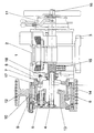
- the single figure shows a cross section through a hoist drive 1.
- the hoist drive 1 shown consists of a drive unit 2, to which a mechanical planetary gear 4 and a safety brake 11 are connected.
- the ring gear 6 of the planetary gear 4 is connected in a rotationally fixed manner to the housing 8 of the drive unit 2 via a screw connection 7 and on the radially outer edge there is a bearing 9 which can be formed with a one-piece outer ring which is between a ring 10 and the rollers of the Bearing 9 is arranged.
- the traction sheave 12 is arranged, which is rotatably connected to the planet carrier 13, which forms the outer boundary of the planetary gear 4.
- the ring 10 and the traction sheave 12 can also be made in one piece.
- the inner central wheel 14 of the planetary gear 4 is rotatably connected to the output shaft 15 of the drive unit 2.
- the inner shaft 16 of the safety brake 11 is rotatably connected to the output shaft 15 of the drive unit 2.
- the inner central wheel 14, the inner shaft 16 of the safety brake 11 and the output shaft 15 of the drive unit 2 can also be made in one piece.
- the radially outer peripheral wall of the ring gear 6 is provided with a sealing ring 17 for liquid-sealing separation.
- the radially inner peripheral wall of the housing 8 of the drive unit 2 on the side facing the planetary gear 4 is provided with a sealing ring 18 for the liquid-tight separation of the planetary gear 4 and the drive unit 2.
- the stand base 3 is either connected in one piece to the drive unit 2 or attached to it.
- the toothing of the planetary gear 4 is preferably designed as a helical toothing, the planets of which are designed as step planets 5.
- the helical toothing of the stepped planet 5 can be designed such that the stepped planet 5 does not generate any external axial forces.
Landscapes
- Engineering & Computer Science (AREA)
- Mechanical Engineering (AREA)
- Retarders (AREA)
- Cage And Drive Apparatuses For Elevators (AREA)
Description
Die für den einzelnen Hebezeugantrieb zur Verfügung stehende Einbaulänge wird in der Regel durch den Aufzugsschacht und den darin benötigten Wartungsraum begrenzt. Da Hebezeugantriebe auch zwischen Aufzugsschacht und Kabine eingebaut sein können ist der radiale Bauraum für den Durchmesser der Treibscheibe begrenzt, welche deshalb einen Maximalwert nicht übersteigen darf. Innerhalb dieser Begrenzungen soll der Hebezeugantrieb mit einem mechanischen Untersetzungsgetriebe in Form eines Planetengetriebes mit einer Lagerung für die Treibscheibe, einer Antriebseinheit und einer Sicherheitsbremse untergebracht werden.
Ein Hebezeugantrieb stellt eine kompakte Antriebseinheit dar, die auf engstem Raum installiert und auch gewartet werden kann. Ein Wechsel der Treibscheibe sollte ohne größeren Aufwand möglich sein.
Bei diesem Hebezeugantrieb wirkt sich der Aufbau des Planetengetriebes nachteilig auf die Baulänge des Antriebes aus, da die Lagerung der Treibscheibe neben den Planetenstufen angebracht ist.
Die Sicherheitsbremse ist in einem separaten Gehäuse untergebracht, welches die Baulänge zusätzlich verlängert.
Die Lagerung der Treibscheibe wird über die Planetenstufe gestellt, durch welches eine weitere Verkürzung erreicht wird, die Laufbahn der Rollen der Lagerung ist hierbei die radial äußere Berandung des Hohlrades. Eine optimale Lagerauslegung der Treibscheibenlagerung ermöglicht die Lageranordnung mittig unter der Krafteileitung der Treibscheibe. Die Lagerung kann ebenfalls neben der Planetenstufe angebracht werden. Der Außenring der Lagerung kann einteilig, womit eine Reduzierung der Teile erreicht wird, oder zweiteilig ausgeführt sein.
Das Gehäuse der Antriebseinheit ist mit einem Ständer ausgeführt, welcher die Montage des Hebezeugantriebes am dafür vorgesehenen Ort erlaubt, das mechanische Getriebe und die Sicherheitsbremse sind jeweils an einer Seite an der Antriebseinheit angebaut. Dadurch entfällt das Gehäuseteil mit Ständerfuß, welches die Bremse umgeben würde. Der die Treibscheibenlagerung umgebende Ring dient gleichzeitig als Auflager für die Treibscheibe. Damit läßt sich ein Treibscheibenwechsel vornehmen, ohne das Getriebe demontieren zu müssen. Ebenfalls besteht die Möglichkeit die Treibscheibe mit dem Ring einstückig auszubilden, oder den Planetenträger, den Ring und die Treibscheibe einstückig auszubilden.
Der dargestellte Hebezeugantrieb 1 besteht aus einer Antriebseinheit 2, mit welcher einerseits ein mechanisches Planetengetriebe 4, und andererseits eine Sicherheitsbremse 11 verbunden ist. Das Hohlrad 6 des Planetengetriebe 4 ist über eine Schraubverbindung 7 mit dem Gehäuse 8 der Antriebseinheit 2 drehfest vebunden und an der radial äußeren Berandung befindet sich eine Lagerung 9, welche mit einen einstückigen Außenring ausgebildet sein kann, welcher zwischen einem Ring 10 und den Rollen des Lagers 9 angeordnet ist. Über dem Ring 10 ist die Treibscheibe 12 angeordnet, welche drehfest mit dem Planetenträger 13 verbunden ist, welcher die äußere Abgrenzung des Planetengetriebes 4 bildet. Der Ring 10 und die Treibscheibe 12 können auch einstückig ausgeführt sein. Das innere Zentralrad 14 des Planetentriebes 4 ist drehfest mit der Ausgangswelle 15 der Antriebseinheit 2 verbunden. Die innere Welle 16 der Sicherheitsbremse 11 ist drehfest mit der Ausgangswelle 15 des Antriebseinheit 2 verbunden. Das innere Zentralrad 14, die innere Welle 16 der Sicherheitsbremse 11 und die Ausgangswelle 15 des Antriebseinheit 2 können auch einstückig ausgeführt sein. Die radial äußeren Umfangswand des Hohlrad 6 ist mit einem Dichtring 17 zur flüssigkeitsdichtenden Trennung versehen. Die radial inneren Umfangswand des Gehäuses 8 der Antriebseinheit 2 auf der dem Planetengetriebe 4 zugewanten Seite, ist mit einem Dichtring 18 zur flüssigkeitsdichtenden Trennung von Planetengetriebe 4 und Antriebseinheit 2 versehen. Der Ständerfuß 3 ist entweder einstückig mit der Antriebseinheit 2 verbunden, oder an diese angebaut. Die Verzahnung des Planetengetriebes 4 ist vorzugsweise als Schrägverzahnung, dessen Planeten als Stufenplaneten 5 ausgebildet sind, ausgeführt. Die Schrägverzahnung der Stufenplaneten 5 kann dergestalt ausgelegt sein, daß die Stufenplaneten 5 keine äußeren Axialkräfte erzeugen.
- 1
- Hebezeugantrieb
- 2
- Antriebseinheit
- 3
- Ständerfuß
- 4
- Planetengetriebe
- 5
- Stufenplaneten
- 6
- Hohlrad
- 7
- Schraubverbindung
- 8
- Gehäuse
- 9
- Lagerung
- 10
- Ring
- 11
- Sicherheitsbremse
- 12
- Treibscheibe
- 13
- Planetenträger
- 14
- inneres Zentralrad
- 15
- Ausgangswelle
- 16
- inere Welle
- 17
- Dichtring
- 18
- Dichtring
Claims (6)
- Hebezeugantrieb (1), bestehend aus einer Antriebseinheit (2), einer Sicherheitsbremse (11) und einem Planetengetriebe (4) mit einem innerem Zentralrad (14), Planeten, einem Hohlrad (6) und einem Planetenträger (13), eine auf einem Planetengetriebe befestigte Treibscheibe (12), einer Lagerung (9) der Treibscheibe und einem Ständerfuß (3) zur Befestigung eines Hebezeugantriebes (1), dadurch gekennzeichnet, daß das Planetengetriebe (4) ein Getriebe mit Stufenplaneten (5) ist, dessen Hohlrad (6) drehfest mit einem Gehäuse (8) einer Antriebseinheit (2) verbunden ist, dessen inneres Zentralrad (14) von einer Ausgangswelle (15) einer Antriebseinheit (2) angetrieben wird, dessen Planetenträger (13) drehfest mit einer Treibscheibe (12) verbunden ist und dessen Treibscheibe (12) über eine Lagerung (9) auf einem Hohlrad (6) gelagert ist.
- Hebezeugantrieb (1) nach Anspruch 1. dadurch gekennzeichnet, daß ein Gehäuse (8) einer Antriebseinheit (2) mit Ständerfuß (3) ausgebildet ist und eine Sicherheitsbremse (11) drehfest mit einem Gehäuse (8) einer Antriebseinheit (2) verbunden ist.
- Hebezeugantrieb (1) nach Anspruch 1, dadurch gekennzeichnet, daß ein Gehäuse (8) einer Antriebseinheit (2) auf der einem Planetengetriebe (4) zugewanten Seite auf seiner radial inneren Umfangswand mit einem Dichtring (18) zur flüssigkeitsdichtenden Trennung von Planetengetriebe (4) und Antriebseinheit (2) versehen ist.
- Hebezeugantrieb (1) nach Anspruch 1, dadurch gekennzeichnet, daß die Verzahnung eines Planetengetriebes (4) als Schrägverzahnung ausgeführt ist, deren Auslegung Axialkräfte von Stufenplaneten (5) verhindert.
- Hebezeugantrieb (1) nach Anspruch 1 dadurch gekennzeichnet, daß eine Lagerung (9) einen einstückigen Außenring aufweist, die Laufbahn der Rollen auf der radial äußeren Berandung eines Hohlrades (6) ist.
- Hebezeugantrieb (1) nach Anspruch 1, dadurch gekennzeichnet, daß die Verzahnung der Stufenplaneten (5) sich mit einem inneren Zentralrad (14) im Eingriff befindet und eine gleichzeitige Eingriffsfolge aufweist.
Applications Claiming Priority (3)
| Application Number | Priority Date | Filing Date | Title |
|---|---|---|---|
| DE19828213 | 1998-06-25 | ||
| DE19828213A DE19828213A1 (de) | 1998-06-25 | 1998-06-25 | Hebezeugantrieb |
| PCT/EP1999/004262 WO1999067168A1 (de) | 1998-06-25 | 1999-06-19 | Hebezeugantrieb |
Publications (2)
| Publication Number | Publication Date |
|---|---|
| EP1089935A1 EP1089935A1 (de) | 2001-04-11 |
| EP1089935B1 true EP1089935B1 (de) | 2002-09-04 |
Family
ID=7871913
Family Applications (1)
| Application Number | Title | Priority Date | Filing Date |
|---|---|---|---|
| EP99929286A Expired - Lifetime EP1089935B1 (de) | 1998-06-25 | 1999-06-19 | Hebezeugantrieb |
Country Status (6)
| Country | Link |
|---|---|
| EP (1) | EP1089935B1 (de) |
| CN (1) | CN1092134C (de) |
| AU (1) | AU4613799A (de) |
| DE (2) | DE19828213A1 (de) |
| ES (1) | ES2179661T3 (de) |
| WO (1) | WO1999067168A1 (de) |
Families Citing this family (3)
| Publication number | Priority date | Publication date | Assignee | Title |
|---|---|---|---|---|
| DE10000221A1 (de) * | 2000-01-05 | 2001-07-12 | Bosch Gmbh Robert | Stellglied für eine Fahrzeug-Lenkvorrichtung |
| DE102004007789A1 (de) | 2004-02-18 | 2005-09-08 | Daimlerchrysler Ag | Toroidgetriebe für ein Kraftfahrzeug |
| US9567024B2 (en) | 2015-04-27 | 2017-02-14 | Timothy LARONDE | Kickstand assembly having gear assembly |
Family Cites Families (7)
| Publication number | Priority date | Publication date | Assignee | Title |
|---|---|---|---|---|
| GB194573A (en) * | 1922-04-13 | 1923-03-15 | Aylmer Augustus Liardet | Improvements in and relating to hoisting gear |
| US1579483A (en) * | 1923-09-06 | 1926-04-06 | Thomas A Conlon | Portable winch |
| FR32122E (fr) * | 1926-08-03 | 1927-09-10 | Treuil monte-charge | |
| US2255574A (en) * | 1936-08-08 | 1941-09-09 | Air Equipment | Winch for use on board aircraft |
| US4162713A (en) * | 1978-04-03 | 1979-07-31 | Otis Engineering Corporation | Planetary transmission with hydraulic engagement and disengagement |
| US5435209A (en) * | 1992-06-26 | 1995-07-25 | Wittur Aufzugteile Gmbh & Co. | Drive unit for a hoisting apparatus, in particular for a passenger or freight elevator |
| DE4435849A1 (de) * | 1994-10-07 | 1996-04-11 | Zahnradfabrik Friedrichshafen | Hebezeugantrieb |
-
1998
- 1998-06-25 DE DE19828213A patent/DE19828213A1/de not_active Withdrawn
-
1999
- 1999-06-19 EP EP99929286A patent/EP1089935B1/de not_active Expired - Lifetime
- 1999-06-19 CN CN99806240A patent/CN1092134C/zh not_active Expired - Fee Related
- 1999-06-19 DE DE59902580T patent/DE59902580D1/de not_active Expired - Fee Related
- 1999-06-19 WO PCT/EP1999/004262 patent/WO1999067168A1/de not_active Ceased
- 1999-06-19 AU AU46137/99A patent/AU4613799A/en not_active Abandoned
- 1999-06-19 ES ES99929286T patent/ES2179661T3/es not_active Expired - Lifetime
Also Published As
| Publication number | Publication date |
|---|---|
| EP1089935A1 (de) | 2001-04-11 |
| ES2179661T3 (es) | 2003-01-16 |
| DE19828213A1 (de) | 1999-12-30 |
| WO1999067168A1 (de) | 1999-12-29 |
| AU4613799A (en) | 2000-01-10 |
| CN1092134C (zh) | 2002-10-09 |
| DE59902580D1 (de) | 2002-10-10 |
| CN1301233A (zh) | 2001-06-27 |
Similar Documents
| Publication | Publication Date | Title |
|---|---|---|
| EP2948406B1 (de) | Seilwinde | |
| EP0734350B1 (de) | Hebezeugantrieb | |
| DE4241141A1 (de) | Verdichteranlage mit einem im Antriebsstrang zwischen einer Antriebseinheit und einem Verdichterbereich der Anlage eingeschalteten Zahnradgetriebe | |
| DE3240345A1 (de) | Seiltrommelantrieb | |
| EP1343982A1 (de) | Planetengetriebe | |
| EP0578069B1 (de) | Antriebseinheit für ein Hebezeug, insbesondere für einen Personen- oder Lastenaufzug | |
| EP3775616A1 (de) | Mehrstufige getriebeanordnung | |
| DE3903517A1 (de) | Stirnradgetriebebaureihen-oberbegriff planetengetriebe | |
| EP2271858B1 (de) | Getriebe mit zwei eintreibenden wellen und einem planetengetriebe als überlagerungsgetriebeeinrichtung | |
| DE3410866C2 (de) | ||
| DE19917608C1 (de) | Schüsselmühlengetriebe | |
| WO2004022375A1 (de) | Direkt angetriebene antriebsachse mit einer ein axial festgelegtes sonnenritzel aufweisenden getriebestufe | |
| EP0442882B1 (de) | Hebezeugantrieb | |
| DE2503174A1 (de) | Zentrifugalverdichter | |
| DE2734487A1 (de) | Konzentrisches untersetzungsgetriebe mit mehreren getriebezuegen | |
| EP1089935B1 (de) | Hebezeugantrieb | |
| WO2008037618A1 (de) | Mehrstufiges untersetzungsgetriebe | |
| DE102015007333A1 (de) | Getriebe mit einem Gehäuse und einer Planetengetriebestufe | |
| DE19530891A1 (de) | Hebezeug, das mit einem Zugmittel betrieben wird | |
| DE4413759A1 (de) | Getriebe für Anlagen zur Personenbeförderung | |
| DE2937564C2 (de) | Regler-Antrieb für automatische Getriebe | |
| DE723405C (de) | Umlaufraedergetriebe mit mehreren Stirnradvorgelegen | |
| DE3342172C2 (de) | Elektrischer Fahrantrieb für einen Kran oder das Fahrwerk eines Hubwerkes etc. | |
| WO1992005372A1 (de) | Planetengetriebe | |
| DE10147853A1 (de) | Getriebe |
Legal Events
| Date | Code | Title | Description |
|---|---|---|---|
| PUAI | Public reference made under article 153(3) epc to a published international application that has entered the european phase |
Free format text: ORIGINAL CODE: 0009012 |
|
| 17P | Request for examination filed |
Effective date: 20000908 |
|
| AK | Designated contracting states |
Kind code of ref document: A1 Designated state(s): CH DE ES LI |
|
| GRAG | Despatch of communication of intention to grant |
Free format text: ORIGINAL CODE: EPIDOS AGRA |
|
| 17Q | First examination report despatched |
Effective date: 20011221 |
|
| GRAG | Despatch of communication of intention to grant |
Free format text: ORIGINAL CODE: EPIDOS AGRA |
|
| GRAH | Despatch of communication of intention to grant a patent |
Free format text: ORIGINAL CODE: EPIDOS IGRA |
|
| GRAH | Despatch of communication of intention to grant a patent |
Free format text: ORIGINAL CODE: EPIDOS IGRA |
|
| GRAA | (expected) grant |
Free format text: ORIGINAL CODE: 0009210 |
|
| AK | Designated contracting states |
Kind code of ref document: B1 Designated state(s): CH DE ES LI |
|
| REG | Reference to a national code |
Ref country code: CH Ref legal event code: EP |
|
| REG | Reference to a national code |
Ref country code: CH Ref legal event code: NV Representative=s name: E. BLUM & CO. PATENTANWAELTE |
|
| REF | Corresponds to: |
Ref document number: 59902580 Country of ref document: DE Date of ref document: 20021010 |
|
| REG | Reference to a national code |
Ref country code: ES Ref legal event code: FG2A Ref document number: 2179661 Country of ref document: ES Kind code of ref document: T3 |
|
| PLBE | No opposition filed within time limit |
Free format text: ORIGINAL CODE: 0009261 |
|
| STAA | Information on the status of an ep patent application or granted ep patent |
Free format text: STATUS: NO OPPOSITION FILED WITHIN TIME LIMIT |
|
| 26N | No opposition filed |
Effective date: 20030605 |
|
| REG | Reference to a national code |
Ref country code: CH Ref legal event code: PFA Owner name: ZF FRIEDRICHSHAFEN AKTIENGESELLSCHAFT Free format text: ZF FRIEDRICHSHAFEN AKTIENGESELLSCHAFT# #88038 FRIEDRICHSHAFEN (DE) -TRANSFER TO- ZF FRIEDRICHSHAFEN AKTIENGESELLSCHAFT# #88038 FRIEDRICHSHAFEN (DE) |
|
| PGFP | Annual fee paid to national office [announced via postgrant information from national office to epo] |
Ref country code: CH Payment date: 20090615 Year of fee payment: 11 |
|
| PGFP | Annual fee paid to national office [announced via postgrant information from national office to epo] |
Ref country code: DE Payment date: 20090615 Year of fee payment: 11 |
|
| PGFP | Annual fee paid to national office [announced via postgrant information from national office to epo] |
Ref country code: ES Payment date: 20100713 Year of fee payment: 12 |
|
| REG | Reference to a national code |
Ref country code: CH Ref legal event code: PL |
|
| PG25 | Lapsed in a contracting state [announced via postgrant information from national office to epo] |
Ref country code: CH Free format text: LAPSE BECAUSE OF NON-PAYMENT OF DUE FEES Effective date: 20100630 Ref country code: DE Free format text: LAPSE BECAUSE OF NON-PAYMENT OF DUE FEES Effective date: 20110101 Ref country code: LI Free format text: LAPSE BECAUSE OF NON-PAYMENT OF DUE FEES Effective date: 20100630 |
|
| REG | Reference to a national code |
Ref country code: ES Ref legal event code: FD2A Effective date: 20120717 |
|
| PG25 | Lapsed in a contracting state [announced via postgrant information from national office to epo] |
Ref country code: ES Free format text: LAPSE BECAUSE OF NON-PAYMENT OF DUE FEES Effective date: 20110620 |