EP1089306A2 - Schaltvorrichtung, insbesondere für eine Gastherme - Google Patents
Schaltvorrichtung, insbesondere für eine Gastherme Download PDFInfo
- Publication number
- EP1089306A2 EP1089306A2 EP00120363A EP00120363A EP1089306A2 EP 1089306 A2 EP1089306 A2 EP 1089306A2 EP 00120363 A EP00120363 A EP 00120363A EP 00120363 A EP00120363 A EP 00120363A EP 1089306 A2 EP1089306 A2 EP 1089306A2
- Authority
- EP
- European Patent Office
- Prior art keywords
- carrier
- switching device
- holder
- switch
- actuating element
- Prior art date
- Legal status (The legal status is an assumption and is not a legal conclusion. Google has not performed a legal analysis and makes no representation as to the accuracy of the status listed.)
- Withdrawn
Links
- 238000006073 displacement reaction Methods 0.000 claims abstract description 4
- 230000006835 compression Effects 0.000 claims description 13
- 238000007906 compression Methods 0.000 claims description 13
- 238000013459 approach Methods 0.000 claims description 12
- XLYOFNOQVPJJNP-UHFFFAOYSA-N water Substances O XLYOFNOQVPJJNP-UHFFFAOYSA-N 0.000 claims description 7
- 230000000694 effects Effects 0.000 abstract description 2
- 238000011161 development Methods 0.000 description 4
- 230000018109 developmental process Effects 0.000 description 4
- 230000008439 repair process Effects 0.000 description 4
- 238000000034 method Methods 0.000 description 2
- 239000000969 carrier Substances 0.000 description 1
- 238000005352 clarification Methods 0.000 description 1
- 230000007423 decrease Effects 0.000 description 1
- 230000001419 dependent effect Effects 0.000 description 1
- 238000013461 design Methods 0.000 description 1
- 238000012549 training Methods 0.000 description 1
Images



Classifications
-
- H—ELECTRICITY
- H01—ELECTRIC ELEMENTS
- H01H—ELECTRIC SWITCHES; RELAYS; SELECTORS; EMERGENCY PROTECTIVE DEVICES
- H01H3/00—Mechanisms for operating contacts
- H01H3/02—Operating parts, i.e. for operating driving mechanism by a mechanical force external to the switch
- H01H3/16—Operating parts, i.e. for operating driving mechanism by a mechanical force external to the switch adapted for actuation at a limit or other predetermined position in the path of a body, the relative movement of switch and body being primarily for a purpose other than the actuation of the switch, e.g. for a door switch, a limit switch, a floor-levelling switch of a lift
- H01H3/166—Self-adjusting mountings, transmissions and the like
Definitions
- the invention relates to a switching device according to the preamble of claim 1.
- Electrical switches are used on gas heaters and gas heaters Recognize movement of a valve rod assembly, which is generated by water flow, to then switch on the ignition spark for the gas burner, for example. Owing to large component tolerances in the valve linkage and the fastening elements in the Gas heaters for the switch must conventionally be the switching point of the electrical Switch can be adjusted in a manual operation, which is both an additional Represents effort, as well as can lead to incorrect settings.
- a brake pedal is used Switching device containing electrical switch arranged an automatic Adjustment of the position of the switch to the brake pedal when the Brake pedals allowed.
- Such a switching device for a motor vehicle is known from DE 40 25 068 A1, which consists of a holder and a support for an electrical switch.
- An in Actuating direction of the switch movable actuator acts on it Movement switches on the electrical switch.
- the carrier and bracket are for adjusting the electrical switch on the actuating element relative to one another in Movable direction of actuation.
- An automatic adjustment takes place at least when the actuating element is actuated for the first time Moving the carrier and / or the holder in the operating direction of the switch against the locking force of the locking means.
- the invention has for its object one for the arrangement on a gas boiler to create suitable switching device in which a manual adjustment process is eliminated can.
- the switching device should have a substantially constant locking force exhibit.
- an additional elastic force acts in the essentially perpendicular to the locking means on the carrier and / or the holder on.
- This elastic force causes an essentially during the period of use Switching device constant locking force with which the locking means the carrier and the Bracket when the actuating element acts on the switch after the automatic Fix the adjustment against each other.
- the latching force can advantageously be achieved by set the appropriate choice of the size of the elastic force as desired. By appropriate choice ensures that a correct automatic adjustment as well as a subsequent error-free operation of the switching device is guaranteed.
- the electrical switch can be a microswitch.
- the Microswitch is expediently by means of fastening pins, locking pins or the like on Carrier fixed.
- the actuator of the switch is the actuator facing.
- the holder is advisable to design the holder with a cover in the manner of a housing.
- the actuating element is then rotatable on the housing against the force of a return spring and conveniently mounted on the bracket.
- the actuator is in further embodiment designed as a two-armed lever, with a lever arm on the Actuator of the electrical switch acts and the other lever arm in Active connection with a valve rod for the water supply to the gas boiler. This other lever arm can be designed in the manner of a fork.
- the carrier is displaceable in the housing in the manner of a carriage and conveniently mounted on the bracket.
- the slide Guide means designed in the manner of tongue and groove on the holder and the carrier arranged.
- Compression spring can be used as a means of exerting the elastic force on the latching means.
- a cup-shaped is then preferably on the carrier configured receptacle for one end of the compression spring.
- the other end of the Compression spring is supported against the bracket and against the cover of the housing.
- a plurality of ratchet teeth arranged equidistantly to one another can be used as the latching means on the Bracket or the carrier and at least one corresponding locking tooth the carrier or the holder can be arranged.
- the locking teeth of the locking means molded in one piece from the same plastic.
- the rotary bearing of the actuating element is on an approach that is supported on the lid of the housing.
- the approach has two surfaces offset from each other and is displaceable such that the Rotary bearing of the actuating element in the non-adjusted state from the higher one Surface and in the adjusted state is supported by the lower surface.
- the beam is offset by a height between the two Corresponding areas released area, which may occur Counteracts tension in the locking means on the carrier and the bracket.
- the height offset between the surfaces is expediently chosen such that the Carrier about half the distance between two locking teeth Appropriate means of locking is released.
- a film hinge can be attached to the lid such that a lid part on the lid is flexible with the approach. The cover part allows a kind in the adjusted state by engaging the pivot bearing for the actuator on the heel between the two Areas of the approach.
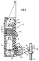
- a switching device 1 for the ignition of a burner serves as a gas heater when the water is switched on.
- the Switching device 1 via an actuating element 3 with one in Fig. 2 schematically indicated valve linkage 2 for the water supply to the gas boiler in operative connection.
- the switching device 1 has a housing 14 which is made of a cover 6 and one designed in the manner of a base, on the gas boiler attached bracket 4 there. Inside the housing 14 there is a carrier 5.
- Am Carrier 5 is an electrical switch 7, which is, for example, a Microswitches can act, arranged.
- the electrical switch 7 is such on the carrier 5 attached that the actuator 10 of the switch 7, the actuator 3rd is facing.
- the carrier 5 has for fixing the Switch 7 on the carrier 5 mounting pin 11, locking pin or the like intervene corresponding receptacles 12 on the switch 7.
- the lid 6 can on the Bracket 4 be snapped on.
- the actuating element 3 is via the valve rod 2 in Actuating direction 22 of the switch 7 is movable, as can be seen in Fig. 2, the Actuating element 3 switching to the electrical switch 7 when it moves acts.
- the switching device 1 permits adjustment of the electrical switch 7, specifically in particular the switching point for the electrical switch 7 in view of that Actuating element 3.
- the carrier 5 and the holder 4 are in the actuating direction 22 slidably arranged relative to each other.
- An additional elastic force that is one of a kind Compression spring 9 exerted spring force acts essentially perpendicular to the Locking means 8 and thus perpendicular to the direction of displacement 22 on the carrier 5th and / or the holder 4.
- the Commissioning of the gas boiler at least when the first operation of the Actuating element 3 an automatic adjustment of the switch 7 via the valve rod 2 instead of.
- the actuating element 3 first actuates the switch 7.
- the actuating element 3 is then on Switch 7 on and then moves the carrier 5 together with the electrical switch 7 in the actuating direction 22 of the switch 7 against the latching force of the latching means 8 the further actuation stroke of the valve rod assembly 2.
- this can Actuator 3 for adjustment also on the holder 4 instead of on the carrier 5 or act both on the bracket 4 and on the carrier 5. Because of the Compression spring 9 exerted elastic force fix the locking means 8 after automatic adjustment of the carrier 5 and the bracket 4 when subsequently in operation the gas thermal effect of the actuator 3 on the actuator of the switch 7 against each other.
- the actuator 3 is a two-armed Lever formed with a pivot bearing 23, a lever arm 15 on the Actuator 10 of the electrical switch 7 acts and the other lever arm 16 in There is an active connection with the valve rod 2 for the water supply to the gas boiler.
- the lever arm 16 is expediently designed in the manner of a fork 17, which 3, wherein the fork 17 comprises the valve rod 2.
- the carrier 5 is displaceable in the housing in the manner of a carriage 14 in the holder 4.
- Fig. 1 guide 18 for example in the type of tongue and groove are configured on the holder 4 and the carrier 5 arranged.
- a receptacle 19 On the carrier 5 is a receptacle 19, which is expediently cup-shaped is configured for one end of the compression spring 9.
- the other end of the Compression spring 9 is supported against the holder 4, namely against the cover 6 of the present Housing 14 from, as can be seen from FIG. 2.
- the latching means 8 consist of several equidistantly mutually arranged locking teeth 20 on the holder 4 and at least one for this corresponding locking tooth 20 'on the carrier 5.
- the one facing the holder 4 Detent tooth 20 'located on the side of the carrier 5 is not per se in the illustration according to FIG. 1 visible and only drawn in for clarification. Of course you can too conversely, several locking teeth on the carrier 5 and a corresponding locking tooth on the bracket 4 or several locking teeth both on the bracket 4 and on Carrier 5 be located.
- the bracket 4 and the carrier 5 are made of plastic.
- the locking teeth 20, 20 'of the locking means 8 are then preferably made of the same Plastic molded in one piece on the bracket 4 and on the carrier 5.
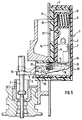
- the cover 6 has in the area of the pivot bearing 23 for the Actuating element 3 has an extension 25 with two surfaces 26, 27, the surfaces 26, 27 have a vertical offset from each other.
- the approach 25 in such a position that the pivot bearing 23 from the higher surface 26th is supported, as shown in Fig. 4.
- the approach 25 is shifted such that the pivot bearing 23 from the lower one Surface 27 is supported, which can be seen in Fig. 5 in more detail.
- This will adjust Operating state of the switching device 1 of the carrier 5 by a height offset between the two surfaces 26, 27 corresponding distance released so that a possibly at the adjustment occurred tension between the ratchet teeth 20, 20 'is reduced.
- the height offset between the surfaces 26, 27 is expediently chosen such that the carrier 5 approximately half the distance between two locking teeth 20 corresponding route is released.
- a type of film hinge 24 can be attached to the cover 6, so that a cover part 28 on the cover 6 to move the extension 25 is movable.
- the lid part 28 is in the unadjusted state slightly above the cover 6, as can be seen from FIG. 4. After adjustment, the cover part 28 is manually engaged so that the cover part 28 in essentially aligned with the cover 6, which is apparent from Fig. 5.
- the Approach 25 shifted accordingly, with the cover part 29 at the same time in FIG. 4 visible paragraph 28 between the two surfaces 26, 27 of the approach 25 through the Pivot bearing 23 is fixed in a kind of snap.
- the invention is not based on the described and illustrated embodiment limited. Rather, it also includes all professional training within the framework of the Invention idea.
- the invention can thus not only be used in gas boilers but can also in other electrical devices, such as electric pumps, power tools o. Like., Use find in which an electrical switch to an actuator adjust.
Landscapes
- Feeding And Controlling Fuel (AREA)
Abstract
Description
- Fig. 1
- eine Schaltvorrichtung mit einem Gehäuse, bei dem der Deckel abgenommen ist,
- Fig. 2
- einen Schnitt entlang der Linie 2-2 aus Fig. 1,
- Fig. 3
- einen Schnitt entlang der Linie 3-3 aus Fig. 1,
- Fig. 4
- einen Schnitt wie in Fig. 2 entsprechend einer weiteren Ausgestaltung, wobei die Schaltvorrichtung während der Justage gezeigt ist, und
- Fig. 5
- die Schaltvorrichtung gemäß Fig. 4 nach der Justage im Betriebszustand.
- 1:
- Schaltvorrichtung
- 2:
- Ventilgestänge (von Wasserzuleitung)
- 3:
- Betätigungselement
- 4:
- Halterung
- 5:
- Träger
- 6:
- Deckel
- 7:
- elektrischer Schalter
- 8:
- Verrastungsmittel
- 9:
- Druckfeder
- 10:
- Betätigungsorgan (von Schalter)
- 11:
- Befestigungszapfen
- 12:
- Aufnahme (am Schalter)
- 13:
- Rückstellfeder
- 14:
- Gehäuse
- 15,16:
- Hebelarm (von Betätigungselement)
- 17:
- Gabel (an Hebelarm)
- 18:
- Führungsmittel
- 19:
- Aufnahme (für Druckfeder)
- 20,20':
- Rastzahn
- 21:
- Öffnung (in der Halterung)
- 22:
- Betätigungsrichtung / Verschieberichtung
- 23:
- Drehlager
- 24:
- Filmscharnier
- 25:
- Ansatz
- 26,27:
- Fläche (am Ansatz)
- 28:
- Deckelteil
- 29:
- Absatz (am Ansatz)
Claims (14)
- Schaltvorrichtung, insbesondere für die Zündung eines Brenners einer Gastherme, mit einer Halterung (4), mit einem Träger (5), an dem ein elektrischen Schalter (7) angeordnet ist, und mit einem in Betätigungsrichtung (22) des Schalters (7) bewegbaren Betätigungselement (3), das bei Bewegung schaltend auf den elektrischen Schalter (7) einwirkt, wobei der Träger (5) und die Halterung (4) relativ zueinander zur Justierung des elektrischen Schalters (7) auf das Betätigungselement (3) in Betätigungsrichtung (22) verschieblich sind, wobei Verrastungsmittel (8) an der Halterung (4) und an dem Träger (5) befindlich sind, die zur Ausübung einer der Verschiebung zwischen dem Träger (5) und der Halterung (4) entgegenwirkenden Rastkraft miteinander zusammenwirken, und wobei eine selbsttätige Justierung zumindest bei der erstmaligen Betätigung des Betätigungselements (3) durch Verschieben des Trägers (5) und/oder der Halterung (4) in Betätigungsrichtung (22) des Schalters (7) gegen die Rastkraft der Verrastungsmittel (8) erfolgt, dadurch gekennzeichnet, daß eine elastische Kraft im wesentlichen senkrecht zu den Verrastungsmitteln (8) auf den Träger (5) und/oder die Halterung (4) einwirkt, derart daß die Verrastungsmittel (8) den Träger (5) und die Halterung (4) bei Einwirkung des Betätigungselements (3) auf den Schalter (7) nach der selbsttätigen Justierung gegeneinander fixieren.
- Schaltvorrichtung nach Anspruch 1, dadurch gekennzeichnet, daß es sich bei dem elektrischen Schalter (7) um einen Mikroschalter handelt, der mittels Befestigungszapfen (11), Rastzapfen o. dgl. derart am Träger (5) fixiert ist, daß das Betätigungsorgan (10) des Schalters (7) dem Betätigungselement (3) zugewandt ist.
- Schaltvorrichtung nach Anspruch 1 oder 2, dadurch gekennzeichnet, daß die in der Art eines Sockels ausgestaltete Halterung (4) zusammen mit einem Deckel (6) ein Gehäuse (14) bildet, in dessen Inneren der Träger (5) angeordnet ist.
- Schaltvorrichtung nach Anspruch 1, 2 oder 3, dadurch gekennzeichnet, daß das Betätigungselement (3) gegen die Kraft einer Rückstellfeder (13) drehbar am Gehäuse (14), insbesondere an der Halterung (4) gelagert ist.
- Schaltvorrichtung nach einem der Ansprüche 1 bis 4, dadurch gekennzeichnet, daß das Betätigungselement (3) als zweiarmiger Hebel mit einem Drehlager (23) ausgebildet ist, wobei ein Hebelarm (15) auf das Betätigungsorgan (10) des elektrischen Schalters (7) einwirkt und der andere Hebelarm (16), der insbesondere in der Art einer Gabel (17) ausgestaltet ist, in Wirkverbindung mit einem Ventilgestänge (2) für die Wasserzuleitung der Gastherme steht.
- Schaltvorrichtung nach einem der Ansprüche 1 bis 5, dadurch gekennzeichnet, daß der Träger (5) in der Art eines Schlittens verschieblich im Gehäuse (14), insbesondere an der Halterung (4), gelagert ist, und daß vorzugsweise Führungsmittel (18) in der Art einer Nut und Feder an der Halterung (4) und dem Träger (5) angeordnet sind.
- Schaltvorrichtung nach einem der Ansprüche 1 bis 6, dadurch gekennzeichnet, daß die elastische Kraft durch eine Druckfeder (9) ausgeübt wird.
- Schaltvorrichtung nach einem der Ansprüche 1 bis 7, dadurch gekennzeichnet, daß am Träger (5) eine insbesondere topfförmig ausgestaltete Aufnahme (19) für das eine Ende der Druckfeder (9) angeordnet ist, und daß das andere Ende der Druckfeder (9) sich gegen das Gehäuse (14), insbesondere gegen den Deckel (6) des Gehäuses (14), abstützt.
- Schaltvorrichtung nach einem der Ansprüche 1 bis 8, dadurch gekennzeichnet, daß die Verrastungsmittel (8) aus mehreren äquidistant zueinander angeordneten Rastzähnen (20) an der Halterung (4) oder dem Träger (5) sowie wenigstens einem hierzu korrespondierenden Rastzahn (20') an dem Träger (5) oder der Halterung (4) bestehen.
- Schaltvorrichtung nach einem der Ansprüche 1 bis 9, dadurch gekennzeichnet, daß die Halterung (4) und der Träger (5) aus Kunststoff bestehen, und daß die Rastzähne (20, 20') der Verrastungsmittel (8) aus demselben Kunststoff einstückig angespritzt sind.
- Schaltvorrichtung nach einem der Ansprüche 1 bis 10, dadurch gekennzeichnet, daß im Gehäuse (14) eine Öffnung (21) angeordnet ist, wobei mit einem Werkzeug durch die Öffnung (21) auf den Träger (5) derart eingewirkt werden kann, daß eine Kraft entgegen der elastischen Kraft auf den Träger (5) ausübbar ist.
- Schaltvorrichtung nach einem der Ansprüche 1 bis 11, dadurch gekennzeichnet, daß am Deckel (6) ein Ansatz (25) mit zwei einen Höhenversatz gegeneinander aufweisenden Flächen (26, 27) angeordnet ist, und daß der Ansatz (25) derart verschiebbar ist, daß das Drehlager (23) des Betätigungselements (3) im nichtjustierten Zustand von der höhergelegenen Fläche (26) und im justierten Zustand von der tiefergelegenen Fläche (27) abgestützt ist, wodurch im justierten Zustand der Träger (5) um eine zum Höhenversatz zwischen den beiden Flächen (26, 27) korrespondierende Strecke freigegeben ist.
- Schaltvorrichtung nach Anspruch 12, dadurch gekennzeichnet, daß der Höhenversatz zwischen den Flächen (26, 27) so gewählt ist, daß der Träger (5) in etwa um eine der halben Entfernung zwischen zwei Rastzähnen (20) der Verrastungsmittel (8) entsprechende Strecke freigegeben ist.
- Schaltvorrichtung nach Anspruch 12 oder 13, dadurch gekennzeichnet, daß am Deckel (6) ein Filmscharnier (24) derart angebracht ist, daß ein Deckelteil (28) am Deckel (6) zur Verschiebung des Ansatzes (25) beweglich ist, und daß das Deckelteil (28) im justierten Zustand durch eine Art von Einrastung des Drehlagers (23) am Absatz (29) zwischen den beiden Flächen (26, 27) des Ansatzes (25) fixierbar ist.
Applications Claiming Priority (2)
| Application Number | Priority Date | Filing Date | Title |
|---|---|---|---|
| DE19946601 | 1999-09-29 | ||
| DE1999146601 DE19946601C1 (de) | 1999-09-29 | 1999-09-29 | Schaltvorrichtung, insbesondere für eine Gastherme |
Publications (2)
| Publication Number | Publication Date |
|---|---|
| EP1089306A2 true EP1089306A2 (de) | 2001-04-04 |
| EP1089306A3 EP1089306A3 (de) | 2002-10-23 |
Family
ID=7923679
Family Applications (1)
| Application Number | Title | Priority Date | Filing Date |
|---|---|---|---|
| EP00120363A Withdrawn EP1089306A3 (de) | 1999-09-29 | 2000-09-16 | Schaltvorrichtung, insbesondere für eine Gastherme |
Country Status (2)
| Country | Link |
|---|---|
| EP (1) | EP1089306A3 (de) |
| DE (1) | DE19946601C1 (de) |
Family Cites Families (11)
| Publication number | Priority date | Publication date | Assignee | Title |
|---|---|---|---|---|
| DE2848875C2 (de) * | 1978-11-10 | 1982-11-18 | Werner Messmer Gmbh & Co Kg, 7760 Radolfzell | Stößelschalter, insbesondere Bremslichtschalter |
| DE3204423C2 (de) * | 1982-02-09 | 1984-06-28 | Bosch-Siemens Hausgeräte GmbH, 7000 Stuttgart | Elektrischer Stufenschalter |
| US4684769A (en) * | 1986-09-08 | 1987-08-04 | Joseph Pollak Corporation | Manual clutch switching system |
| IT210892Z2 (it) * | 1987-03-18 | 1989-01-30 | Turatti Mario | Interruttore elettrico a pulsante associabile al pedale del freno di un autoveicolo |
| DE3711138A1 (de) * | 1987-04-02 | 1988-10-13 | Licentia Gmbh | Antrieb zum fernbetaetigten ein- und ausschalten eines selbstschalters |
| DE3724927A1 (de) * | 1987-07-28 | 1989-02-09 | Bayerische Motoren Werke Ag | Schalteinrichtung mit einem schaltelement und einem betaetigungselement |
| FR2633443B1 (fr) * | 1988-06-27 | 1995-06-09 | Bendix France | Contacteur electrique pour servomoteur pneumatique de freinage |
| DE8810036U1 (de) * | 1988-08-05 | 1988-12-01 | Reitter & Schefenacker KG, 73730 Esslingen | Justiereinrichtung für mechanische und/oder elektronische Postitionsgeber, insbesondere für den Kraftfahrzeugbereich |
| DE4025068A1 (de) * | 1990-08-08 | 1992-02-13 | Daimler Benz Ag | Verfahren zur selbsttaetigen justierung einer elektrischen schalteinrichtung und selbsttaetig justierbare elektrische schalteinrichtung |
| JP3109635B2 (ja) * | 1993-09-17 | 2000-11-20 | アルプス電気株式会社 | プランジャスイッチ |
| DE19645059C1 (de) * | 1996-10-31 | 1997-10-30 | Trw Fahrzeugelektrik | Selbstjustierender Stößelschalter, insbesondere KFZ-Bremslichtschalter |
-
1999
- 1999-09-29 DE DE1999146601 patent/DE19946601C1/de not_active Expired - Fee Related
-
2000
- 2000-09-16 EP EP00120363A patent/EP1089306A3/de not_active Withdrawn
Also Published As
| Publication number | Publication date |
|---|---|
| EP1089306A3 (de) | 2002-10-23 |
| DE19946601C1 (de) | 2001-06-07 |
Similar Documents
| Publication | Publication Date | Title |
|---|---|---|
| DE102011083524B4 (de) | Dreh-/Drück-Bedienvorrichtung für ein Mensch-Maschine-Interface | |
| DE102016117783B4 (de) | Elektrischer Schalter | |
| DE3230414C3 (de) | ||
| DE3315093A1 (de) | Barometer | |
| EP0235350B1 (de) | Schalter, insbesondere für Kraftfahrzeuge | |
| DE10241048B4 (de) | Schalteinrichtung für eine Fahrzeughupe | |
| EP0835196A1 (de) | Antriebsvorrichtung | |
| DE1655102B2 (de) | Vorrichtung zum Stellen von Regeleinrichtungen in Kraftfahrzeugen | |
| DE2700691C3 (de) | Druckschalter für eine elektronische Uhr | |
| DE1580714B1 (de) | Schalteinrichtung,insbesondere fuer Lenkstockschalter an Kraftfahrzeugen | |
| DE3803125C1 (en) | Electrical switch | |
| EP0523645A2 (de) | Elektrischer Schalter | |
| DE3121659C2 (de) | Lenkstockschalter mit einem Warnblinkschalter | |
| EP1443533B1 (de) | Elektrische Schalter | |
| DE4240218C2 (de) | Schaltvorrichtung | |
| DE19946601C1 (de) | Schaltvorrichtung, insbesondere für eine Gastherme | |
| DE19928194B4 (de) | Bewegungsdämpferanordnung mit integriertem Tastschalter insbesondere für Kraftfahrzeuge | |
| DE3514708A1 (de) | Drehpotentiometer mit schalter | |
| DE4439008C2 (de) | Elektrischer Tastschalter | |
| EP3367407B1 (de) | Elektrisches/elektronisches steuergerät | |
| DE3048371A1 (de) | Zweirichtungsschalter | |
| DE2516070B2 (de) | Elektrischer schalter | |
| DE3940285C2 (de) | ||
| DE102021126433B3 (de) | Installationselement für elektrische Anschlusseinheiten | |
| EP1236214A1 (de) | Vakuumschütz mit verschiebbarem führungselement |
Legal Events
| Date | Code | Title | Description |
|---|---|---|---|
| PUAI | Public reference made under article 153(3) epc to a published international application that has entered the european phase |
Free format text: ORIGINAL CODE: 0009012 |
|
| AK | Designated contracting states |
Kind code of ref document: A2 Designated state(s): AT BE CH CY DE DK ES FI FR GB GR IE IT LI LU MC NL PT SE |
|
| AX | Request for extension of the european patent |
Free format text: AL;LT;LV;MK;RO;SI |
|
| PUAL | Search report despatched |
Free format text: ORIGINAL CODE: 0009013 |
|
| AK | Designated contracting states |
Kind code of ref document: A3 Designated state(s): AT BE CH CY DE DK ES FI FR GB GR IE IT LI LU MC NL PT SE |
|
| AX | Request for extension of the european patent |
Free format text: AL;LT;LV;MK;RO;SI |
|
| 17P | Request for examination filed |
Effective date: 20020712 |
|
| AKX | Designation fees paid |
Designated state(s): AT BE CH CY DE DK ES FI FR GB GR IE IT LI LU MC NL PT SE |
|
| D17P | Request for examination filed (deleted) | ||
| DBV | Designated contracting states (deleted) | ||
| REG | Reference to a national code |
Ref country code: DE Ref legal event code: 8566 |
|
| STAA | Information on the status of an ep patent application or granted ep patent |
Free format text: STATUS: THE APPLICATION IS DEEMED TO BE WITHDRAWN |
|
| 18D | Application deemed to be withdrawn |
Effective date: 20030424 |