EP1088528A1 - Stents pour angioplastie - Google Patents
Stents pour angioplastie Download PDFInfo
- Publication number
- EP1088528A1 EP1088528A1 EP00120834A EP00120834A EP1088528A1 EP 1088528 A1 EP1088528 A1 EP 1088528A1 EP 00120834 A EP00120834 A EP 00120834A EP 00120834 A EP00120834 A EP 00120834A EP 1088528 A1 EP1088528 A1 EP 1088528A1
- Authority
- EP
- European Patent Office
- Prior art keywords
- stent
- segment
- bridge elements
- segments
- tubular blank
- Prior art date
- Legal status (The legal status is an assumption and is not a legal conclusion. Google has not performed a legal analysis and makes no representation as to the accuracy of the status listed.)
- Granted
Links
Images


Classifications
-
- A—HUMAN NECESSITIES
- A61—MEDICAL OR VETERINARY SCIENCE; HYGIENE
- A61F—FILTERS IMPLANTABLE INTO BLOOD VESSELS; PROSTHESES; DEVICES PROVIDING PATENCY TO, OR PREVENTING COLLAPSING OF, TUBULAR STRUCTURES OF THE BODY, e.g. STENTS; ORTHOPAEDIC, NURSING OR CONTRACEPTIVE DEVICES; FOMENTATION; TREATMENT OR PROTECTION OF EYES OR EARS; BANDAGES, DRESSINGS OR ABSORBENT PADS; FIRST-AID KITS
- A61F2/00—Filters implantable into blood vessels; Prostheses, i.e. artificial substitutes or replacements for parts of the body; Appliances for connecting them with the body; Devices providing patency to, or preventing collapsing of, tubular structures of the body, e.g. stents
- A61F2/82—Devices providing patency to, or preventing collapsing of, tubular structures of the body, e.g. stents
- A61F2/86—Stents in a form characterised by the wire-like elements; Stents in the form characterised by a net-like or mesh-like structure
- A61F2/90—Stents in a form characterised by the wire-like elements; Stents in the form characterised by a net-like or mesh-like structure characterised by a net-like or mesh-like structure
- A61F2/91—Stents in a form characterised by the wire-like elements; Stents in the form characterised by a net-like or mesh-like structure characterised by a net-like or mesh-like structure made from perforated sheet material or tubes, e.g. perforated by laser cuts or etched holes
- A61F2/915—Stents in a form characterised by the wire-like elements; Stents in the form characterised by a net-like or mesh-like structure characterised by a net-like or mesh-like structure made from perforated sheet material or tubes, e.g. perforated by laser cuts or etched holes with bands having a meander structure, adjacent bands being connected to each other
-
- A—HUMAN NECESSITIES
- A61—MEDICAL OR VETERINARY SCIENCE; HYGIENE
- A61F—FILTERS IMPLANTABLE INTO BLOOD VESSELS; PROSTHESES; DEVICES PROVIDING PATENCY TO, OR PREVENTING COLLAPSING OF, TUBULAR STRUCTURES OF THE BODY, e.g. STENTS; ORTHOPAEDIC, NURSING OR CONTRACEPTIVE DEVICES; FOMENTATION; TREATMENT OR PROTECTION OF EYES OR EARS; BANDAGES, DRESSINGS OR ABSORBENT PADS; FIRST-AID KITS
- A61F2/00—Filters implantable into blood vessels; Prostheses, i.e. artificial substitutes or replacements for parts of the body; Appliances for connecting them with the body; Devices providing patency to, or preventing collapsing of, tubular structures of the body, e.g. stents
- A61F2/82—Devices providing patency to, or preventing collapsing of, tubular structures of the body, e.g. stents
- A61F2/86—Stents in a form characterised by the wire-like elements; Stents in the form characterised by a net-like or mesh-like structure
- A61F2/90—Stents in a form characterised by the wire-like elements; Stents in the form characterised by a net-like or mesh-like structure characterised by a net-like or mesh-like structure
- A61F2/91—Stents in a form characterised by the wire-like elements; Stents in the form characterised by a net-like or mesh-like structure characterised by a net-like or mesh-like structure made from perforated sheet material or tubes, e.g. perforated by laser cuts or etched holes
- A61F2/915—Stents in a form characterised by the wire-like elements; Stents in the form characterised by a net-like or mesh-like structure characterised by a net-like or mesh-like structure made from perforated sheet material or tubes, e.g. perforated by laser cuts or etched holes with bands having a meander structure, adjacent bands being connected to each other
- A61F2002/91533—Stents in a form characterised by the wire-like elements; Stents in the form characterised by a net-like or mesh-like structure characterised by a net-like or mesh-like structure made from perforated sheet material or tubes, e.g. perforated by laser cuts or etched holes with bands having a meander structure, adjacent bands being connected to each other characterised by the phase between adjacent bands
- A61F2002/91541—Adjacent bands are arranged out of phase
-
- A—HUMAN NECESSITIES
- A61—MEDICAL OR VETERINARY SCIENCE; HYGIENE
- A61F—FILTERS IMPLANTABLE INTO BLOOD VESSELS; PROSTHESES; DEVICES PROVIDING PATENCY TO, OR PREVENTING COLLAPSING OF, TUBULAR STRUCTURES OF THE BODY, e.g. STENTS; ORTHOPAEDIC, NURSING OR CONTRACEPTIVE DEVICES; FOMENTATION; TREATMENT OR PROTECTION OF EYES OR EARS; BANDAGES, DRESSINGS OR ABSORBENT PADS; FIRST-AID KITS
- A61F2/00—Filters implantable into blood vessels; Prostheses, i.e. artificial substitutes or replacements for parts of the body; Appliances for connecting them with the body; Devices providing patency to, or preventing collapsing of, tubular structures of the body, e.g. stents
- A61F2/82—Devices providing patency to, or preventing collapsing of, tubular structures of the body, e.g. stents
- A61F2/86—Stents in a form characterised by the wire-like elements; Stents in the form characterised by a net-like or mesh-like structure
- A61F2/90—Stents in a form characterised by the wire-like elements; Stents in the form characterised by a net-like or mesh-like structure characterised by a net-like or mesh-like structure
- A61F2/91—Stents in a form characterised by the wire-like elements; Stents in the form characterised by a net-like or mesh-like structure characterised by a net-like or mesh-like structure made from perforated sheet material or tubes, e.g. perforated by laser cuts or etched holes
- A61F2/915—Stents in a form characterised by the wire-like elements; Stents in the form characterised by a net-like or mesh-like structure characterised by a net-like or mesh-like structure made from perforated sheet material or tubes, e.g. perforated by laser cuts or etched holes with bands having a meander structure, adjacent bands being connected to each other
- A61F2002/9155—Adjacent bands being connected to each other
- A61F2002/91583—Adjacent bands being connected to each other by a bridge, whereby at least one of its ends is connected along the length of a strut between two consecutive apices within a band
-
- A—HUMAN NECESSITIES
- A61—MEDICAL OR VETERINARY SCIENCE; HYGIENE
- A61F—FILTERS IMPLANTABLE INTO BLOOD VESSELS; PROSTHESES; DEVICES PROVIDING PATENCY TO, OR PREVENTING COLLAPSING OF, TUBULAR STRUCTURES OF THE BODY, e.g. STENTS; ORTHOPAEDIC, NURSING OR CONTRACEPTIVE DEVICES; FOMENTATION; TREATMENT OR PROTECTION OF EYES OR EARS; BANDAGES, DRESSINGS OR ABSORBENT PADS; FIRST-AID KITS
- A61F2230/00—Geometry of prostheses classified in groups A61F2/00 - A61F2/26 or A61F2/82 or A61F9/00 or A61F11/00 or subgroups thereof
- A61F2230/0002—Two-dimensional shapes, e.g. cross-sections
- A61F2230/0028—Shapes in the form of latin or greek characters
- A61F2230/0054—V-shaped
-
- A—HUMAN NECESSITIES
- A61—MEDICAL OR VETERINARY SCIENCE; HYGIENE
- A61F—FILTERS IMPLANTABLE INTO BLOOD VESSELS; PROSTHESES; DEVICES PROVIDING PATENCY TO, OR PREVENTING COLLAPSING OF, TUBULAR STRUCTURES OF THE BODY, e.g. STENTS; ORTHOPAEDIC, NURSING OR CONTRACEPTIVE DEVICES; FOMENTATION; TREATMENT OR PROTECTION OF EYES OR EARS; BANDAGES, DRESSINGS OR ABSORBENT PADS; FIRST-AID KITS
- A61F2250/00—Special features of prostheses classified in groups A61F2/00 - A61F2/26 or A61F2/82 or A61F9/00 or A61F11/00 or subgroups thereof
- A61F2250/0014—Special features of prostheses classified in groups A61F2/00 - A61F2/26 or A61F2/82 or A61F9/00 or A61F11/00 or subgroups thereof having different values of a given property or geometrical feature, e.g. mechanical property or material property, at different locations within the same prosthesis
- A61F2250/0036—Special features of prostheses classified in groups A61F2/00 - A61F2/26 or A61F2/82 or A61F9/00 or A61F11/00 or subgroups thereof having different values of a given property or geometrical feature, e.g. mechanical property or material property, at different locations within the same prosthesis differing in thickness
Definitions
- the present invention relates to stents for angioplasty.
- the invention relates to a stent having a cellular design.
- stent is intended to indicate devices useful for endoluminal insertion (for example, in a blood vessel), usually effected by means of catheterization, with subsequent deployment in place so as to achieve local support of the lumen.
- the primary purpose of the stent is to eliminate and avoid the restenosis (i.e., narrowing or closure) of the treated area.
- a stent is subject to various forces, including compression, flexure, and torsion. These stresses often cause the stent to perform in an undesirable manner. Additionally, a significant disadvantage of current stent designs is their failure to distribute these stresses throughout the structure of the stent. Each of these stresses is maximized in a particular area of the stent. In current stent designs two or more of these areas of maximum stress overlap. This results in at least two problems. First, an overlap of the maximum stress areas may overly fatigue the stent and cause failure in an area of overlapped maximum stress. Second, the failure to distribute or discharge the maximum stress of these forces at different areas causes stress concentration on the vessel wall which may cause vessel wall injury. Thus what is needed in the art is a stent meeting the requirements listed above that will avoid stress concentration and elastic distortion as well as provide good elastic matching between the stent and the vessel into which it is placed.
- This invention is primarily a method of making a stent having the features set forth in the annexed claims.
- the invention also relates to the respective stent.
- a stent is inserted into a lumen, such as a blood vessel, at a site where stenosis, i.e., narrowing or stricture, is to be corrected.
- the stent is a tubular envelope, tubular body, or cylinder having apertured walls, such as, for example, a mesh-like structure.
- the stent typically has dimensions between several millimeters and several tens of millimeters in length, and a wall thickness of the order of, for example, several hundredths of millimeters.
- the stent is normally positioned in situ by catheterization through the vasculature followed by radial expansion from an introduction diameter of, for example, about 1.0 to 1.5 mm, to an expanded diameter of, for example, about 3 to 4 mm.
- the stent exerts a supporting force on the lumen, thereby avoiding or at least slowing restenosis of the vessel.
- the external diameter of the stent in the radially-contracted condition is chosen to enable the introduction of the stent into a lumen, while the expanded diameter corresponds to the diameter required to be maintained in the lumen once the stenosis has been eliminated. It should also be remembered that, although the principle application of the stent described is in relation to the treatment of blood vessels, it may also be useful as a support element for any lumen present in the human or animal body.
- the stent of this invention is a tubular body, i.e., a cylinder, with an open, or apertured, mesh-like structure.
- the stent is capable of being dilated from a radially-contracted position to a radially-expanded position.
- the tubular body is comprised of a wall having an inner surface and an outer surface defining a radial stent thickness therebetween.
- the material making up the mesh-like structure of the stent varies in its cross-sectional shape and/or cross-sectional area.
- this cross-sectional variation (and thus a variation in thickness and/or width in the stent wall) produces a particularly desirable stent because the strength, flexibility, and support of the stent may be varied in localized areas.
- the width as measured along the circumference of the tubular body and/or the radial thickness are made smaller to enhance flexibility.
- the width and/or thickness are made larger.
- the width is increased to provide added vascular support.
- the stent is shown in planar views so that the geometry of the stent may be seen easily.
- the body of the stent extends longitudinally in the direction identified as the Z axis. It also lies in the Z plane, i.e., a plane coincident with the Z axis.
- the stent may be flexed, bent or folded; thus good flexibility is one of the required characteristics of the stent.
- Another important characteristic of both the design and the material of the stent includes strength, i.e., the ability to withstand stresses due to compression, flexure, and torsion, as discussed further below.
- Figure 1 illustrates a plan view of the stent of this invention.
- the body of stent 1 is comprised of a plurality of successive segments 2 of generally annular form.
- Figure 1 shows a stent comprising eight annular segments 2.
- the length of segments 2 measured in the longitudinal direction may range up to several millimeters (mm) but preferably is approximately 2 mm. That is, segments 2 are fairly "short" in comparison to the total length of the stent.
- bridge elements 8 which are actually integral components of the stent wall
- Radiopaque marker 13 optionally is provided. Marker 13 is integral with segments 2 and typically is located on the proximal and/or distal ends of the stent. "Proximal and distal ends" refers to the portion of the stent nearest and farthest, respectively, from the point of entry of the stent into the vasculature. Suitable radiopaque markers include metals such as platinum, tantalum, gold, and alloys of these metals. Such markers permit exact placement of a stent within the vasculature of a patient. During manufacture the radiopaque marker may be crimped into a hole in the stent wall.
- the longitudinal flexibility of stent 1, necessary to assist in its delivery and location at the implantation site, is essentially due to bridge elements 8, while its structural strength, that is, its support of the lumen, is due primarily to the structure of segments 2.
- the desired characteristics of the stent can be obtained by adapting the arrangement and relationship of the bridge elements and the segments.
- Figure 1 shows a plan view of a stent which has been cut open and laid flat; that is, the stent is no longer in a tubular shape.
- Figure 1 illustrates that each segment 2 has a serpentine or sinusoidal wave shape.
- Each segment comprises peaks 4 and valleys 6.
- Each annular segment is a mirror image of an adjacent annular segment about a plane perpendicular to the longitudinal axis of the stent. Thus, the peaks of one segment are aligned longitudinally with valleys of an adjacent segment.
- the term "sinusoidal wave shape" means that the annular segments have an undulating repeating pattern similar to that of a sine wave. It is not intended to mean that the shape is limited to that of a sine wave.
- Bridge elements 8 separate adjacent segments and maintain a distance between them in both the expanded and contracted conditions.
- Each bridge element 8 comprises a concave portion, or U-shape 10, having apex 12.
- the U-shape is adjoined to two connector arms 14 which extend from the U-shape and adjoin adjacent sinusoidal-shaped segments 2 at a zero point of the sinusoidal wave shape of each segment.
- the point of connection is between a peak and a valley of each segment such that the apex of the U-shape extends in the direction of the converging peak and valley that is nearest the attachment of the connector arm. These arms extend away from the U-shape and curve back to join the segments in the direction of the apex of the U-shape.
- these arms form an angle ⁇ of about 90 degrees with the U-shape.
- Bridge elements 8 are relatively flexible and change shape only slightly from the contracted to the expanded condition, as can be seen in Figures 1 and 2. Arms 14 adjoin adjacent sinusoidal wave shaped segments between a peak and a valley and preferably at zero-point 11 of the sinusoidal shape. (On a sine curve plotted on an X and Y axis, the "zero-point" is that point that intersects the X axis.)
- FIGS 1 and 2 illustrate an embodiment of the stent of this invention wherein the connector arms of each bridge element adjoin alternate zero points of each adjacent segment. That is, in terms of the sinusoidal wave shape of each segment, bridge elements are connected at zero points separated by 360°. This results in even spacing of bridge elements between adjacent segments.
- the bridge elements are oriented in the same direction; that is, the U-shaped portion of each bridge element faces the same direction. It has been found that connection of the bridge elements at the zero points not only produces a very elastic joint but also results in the longitudinal length of the stent being the same in the contracted condition and the expanded condition and in all degrees of expansion therebetween.
- FIG. 1 A radially-contracted condition of the stent is illustrated in Figure 1. This condition is slightly expanded from the stents fully contracted delivery condition so that the details of the stents structure may be more clearly shown.
- Figure 2 shows that a segment 2 is elongated compared to the same segment in Figure 1. That is, the segments retain the sinusoidal shape, but the amplitude and the frequency of the sine wave is less in the expanded condition than in the contracted condition.
- Figures 1 and 2 also show that the connector arms 14 remain substantially parallel to the longitudinal axis of the stent in both the radially contracted position (Figure 1) and radially expanded position ( Figure 2).
- FIG. 3(a) is a view of one cell of the stent of Figure 2.
- Figures 1 and 2 illustrate that the stent is made up of individual, interconnected cells, each cell having the same size and shape.
- Figures 3(b) to 3(f) illustrate that the cross sectional shape and area of the material making up the stent varies over the cell.
- the perimeter of a cell is formed from portions of adjacent sinusoidal segments (2a and 2b) and two bridge elements (8a and 8b). Sinusoidal segment portions 2a and 2b are 360° portions of the sinusoidal wave shape of the annular segments.
- Arms 14a and 14a' extend from U-shape portion 10a of bridge element 8a.
- Apex 12a of bridge 8a is oriented in the same direction as apex 12b of bridge 8b.
- Bridges 8a and 8b adjoin adjacent segments 2a and 2b at zero points 11 of the sinusoidal shape; that is, between the peaks and valleys of the segments.
- Bridge element 8b having U-shape 10b, apex 12b, and arms 14b and 14b', forms the remainder of the cell.
- Figures 3(b), 3(c), 3(d), 3(e) and 3(f) show the shape and size of the cross-section of different portions of the cell taken along lines b-b, c-c, d-d, e-e and f-f respectively. It is preferred that the cross-sectional area of the material making up the stent vary. The cross-sectional shape may vary as well. An alternate way of describing this is that the width of the material making up the stent of Figures 1 and 2 (i.e., the width of any portion of a bridge or a sinusoidal segment in plane Z) may be different than the thickness of that portion (i.e., the dimension in a plane X, perpendicular to plane Z). It has been found that varying the cross-sectional area of different portions of the material of the stent produces optimum strength, flexibility, and support, enabling the stent to accommodate the differing stresses it encounters during use.
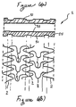
- Figures 4(a) to 4(f) illustrate the effects of compression, flexure, and torsion, respectively, on one cell of the stent of this invention.
- the arrows indicate the direction of the forces applied to the stent.
- the areas of the stent cell having the greatest stress concentration are indicated by solid lines.
- Figure 4(a) the stent is subjected to a compression force.
- Figure 4(b) shows that the areas of greatest stress occurs at the peaks and valleys of the sinusoidal shaped segments.
- Figure 4(c) shows s stent undergoing flexure.
- Figure 4(d) indicates that the areas of greatest stress occur at the apex of the U-shape of the bridge.
- Figure 4(e) shows a stent under torsion.
- Figure 4(f) indicates that the maximum stress occurs at the areas where the bridge joins the sinusoidal shaped segments, i.e., at the zero point.
- One way to do this is to form the desired wall geometry in a continuous tubular blank and then cut or machine the stent from this blank. For example, techniques such as laser incision, photo-incision, and electroerosion may be used to form a desired geometry. In this way, the stent bridges and sinusoidal segments are formed.
- Figure 5a shows a continuous tubular blank from which stents can be formed.
- the tubular blank has outer surface 51 forming the outer diameter and inner surface 53 forming the inner diameter; surfaces 51 and 53 are separated by wall thickness 55.
- the characteristics of the stent including wall thickness and shape can be varied in accordance with the shape and surface configuration of inner and outer surfaces 53 and 51 of the tubular blank. Accordingly, the wall of the stent may be formed so that it has a variety of cross sectional shapes.
- Figures 5(b) to 5(f) show a section or slice of differently shaped tubular blanks between lines a-a' and illustrate various wall shapes.
- the inner and outer surfaces of the tubular blank may be substantially parallel as in Figure 5b.
- the surface configuration of the outer and/or inner surfaces may be varied as in Figures 5(c) to 5(f).
- the inner diameter of the tube may be constant and the outer diameter may vary, as in Figure 5(c), or the converse, as in Figure 5(d), may be used.
- Figures 5(e) and 5(f) illustrate tube walls having variable inside and outside diameters. Such tubular blanks are then machined to form the desired stent as described above. The result is that the desired thicknesses and widths can be provided to different portions of the stent.
- Figures 6(a) and 6(b) show a further embodiment of the invention and illustrate how the shape of the wall of a continuous tubular blank corresponds to the stent of this invention.
- Figure 6(a) shows a longitudinal cross-section of a portion of a tubular blank having a constant inner diameter but varying outer diameter. This blank is then used to form the sinusoidal segments and bridges of the stent.
- Figure 6(b) shows that the regions of the bridges adjoining the sinusoidal shaped segments (i.e., at the zero point) may be made with a smaller thickness than the remaining portions of the stent.
- This stent comprises bridge elements 78 adjoining sinusoidal shaped segments 72 at zero points 71 of the sinusoidal shape.
- the bridge elements are evenly spaced.
- the bridge elements are spaced apart 720° along the sinusoidal shape of the segments.
- the apices of each bridge element face the same direction.
- the stent of Figure 4 illustrates cells all having the same shape and size. In contrast to Figures 1 and 2, this stent has fewer connecting bridges and fewer cells.
- the stent of Figure 8 is a hybrid of Figures 1 and 6.
- Bridge elements 88 adjoin adjacent segments 82 at zero points 81 of the sinusoidal shape. All bridge elements are oriented similarly (i.e., face the same direction). The bridge elements adjoining adjacent segments are evenly spaced. However, the number and spacing of bridge elements is not the same for each pair of adjacent segments. This results in cells of unequal size and may produce regions of variable flexibility as well as strength.
- An advantage to having a greater number of bridge elements (and hence cells) at either end of the stent is that they provide additional stability and strength to the ends of the stent while having fewer cells in the middle portion of the stent provides additional flexibility.
- FIG. 9 Another variation of the stent is illustrated in Figure 9.
- the bridge elements are evenly spaced throughout the stent, forming cells all of equal size and shape.
- apices for example, 90a and 90b
- apices face opposite directions in adjacent pairs of segments 92.
- Figure 10 illustrates yet another variation of the stent, wherein U-shaped portions 100a and 100b of bridge elements 108a and 108b, respectively, are facing in opposite directions in adjacent pairs of segments 102 and wherein the cells formed at each end of the stent are of different size than those of the remaining cells.
- the bridge elements adjoining any pair of adjacent segments are evenly spaced, but the number and spacing of bridge elements is not the same for each pair of adjacent segments. This results in cells of unequal size, and, in similar fashion to Figure 8, produces regions of greater strength at either end of the stent.
- the stent cell structure is sufficiently open to permit access to the lumen. For example, it is possible to manipulate catheters through the stent wall into vessel bifurcations in order to treat those vessels.
- the stent geometry provides a smooth profile for delivery when in the contracted position.
- the U-shape of the connecting bridges lies between a converging valley and peak of adjacent sinusoidal segments and acts as a bridge therebetween.
- peaks or valleys of some prior art stents protrude especially when the stent is bent during delivery. This protruding peak or valley can snag on a vessel wall or plaque, making delivery and positioning of the stent difficult.
- a further advantage is provided by the configuration of the bridge elements.
- the connector arms and U-shaped portion of the bridge elements act in cooperation with the segments to provide an effective support surface for the vessel wall while at the same time minimizing the amount of stent material which must be used.
- the most widely used method is to use a balloon catheter, disposing the stent about the balloon of the catheter in the contracted condition and then expanding the balloon once the stent has been delivered to the deployment site.
- Different solutions are also possible, such as using superelastic materials that expand when the stent reaches the implantation site. Typically these materials are held in a contracted condition by means of a containment element that is released when the stent has reached the desired location and position.
- Materials having a "shape memory" that expand from a first configuration to a second expanded configuration when heated to a transition temperature (i.e., body temperature) also may be used in order to achieve the radial expansion in the implant position.
- the stent is made from a metal capable of satisfying two fundamental requirements: the ability to deform during the expansion phase and the ability to resist forces which could lead to contraction of the stent. That is, the stent retains the expanded shape.
- the stents of this invention may comprise 316 stainless steel or a shape memory material known under the commercial designation "Nitinol". "Nitinol” is a nickel-titanium alloy that has been shown to be successful due to its superelasticity as well as its shape memory. Stents also may comprise biodegradable and/or biocompatible polymers, as known to one of skill in the art.
- the stent of this invention comprises a tubular body with an apertured wall.
- Methods of making the stent include, i.a.:
- the first arrangement described is the one currently preferred for producing stents of this invention.
- the use of laser beams to cut a continuous tubular blank has been shown to be the most flexible way to modify rapidly the characteristics of the stent during production.
- Such methods may be used to produce a stent having a variable wall thickness, and, in either case, with wall material having different cross-sections. These methods include making the stent from a continuous tubular blank and machining, grinding, chemically etching, or electron discharge machining the tube to produce the desired pattern and also obtain sections of desired cross-section. Alternatively, a tubular blank having variable thickness down its length could be laser cut to form the desired arrangement of segments and bridges. A stent could be formed and then the inside surface could be turned or micro-etched.
- the production method is not critical to the stents of this invention, as they may be formed by any desired method. This applies to the choice of the individual techniques and the order in which the various operations (the production of the apertured parts, segmentation, possible folding of the strip-like element, etc.) are performed.
Landscapes
- Health & Medical Sciences (AREA)
- Engineering & Computer Science (AREA)
- Biomedical Technology (AREA)
- Life Sciences & Earth Sciences (AREA)
- General Health & Medical Sciences (AREA)
- Cardiology (AREA)
- Oral & Maxillofacial Surgery (AREA)
- Transplantation (AREA)
- Heart & Thoracic Surgery (AREA)
- Vascular Medicine (AREA)
- Physics & Mathematics (AREA)
- Animal Behavior & Ethology (AREA)
- Optics & Photonics (AREA)
- Public Health (AREA)
- Veterinary Medicine (AREA)
- Media Introduction/Drainage Providing Device (AREA)
- Prostheses (AREA)
- Crystals, And After-Treatments Of Crystals (AREA)
- Surgical Instruments (AREA)
- Laser Surgery Devices (AREA)
Applications Claiming Priority (2)
| Application Number | Priority Date | Filing Date | Title |
|---|---|---|---|
| US410303 | 1999-10-01 | ||
| US09/410,303 US6451049B2 (en) | 1998-04-29 | 1999-10-01 | Stents for angioplasty |
Publications (2)
| Publication Number | Publication Date |
|---|---|
| EP1088528A1 true EP1088528A1 (fr) | 2001-04-04 |
| EP1088528B1 EP1088528B1 (fr) | 2006-10-25 |
Family
ID=23624143
Family Applications (1)
| Application Number | Title | Priority Date | Filing Date |
|---|---|---|---|
| EP00120834A Expired - Lifetime EP1088528B1 (fr) | 1999-10-01 | 2000-09-25 | Stents pour angioplastie |
Country Status (6)
| Country | Link |
|---|---|
| US (2) | US6451049B2 (fr) |
| EP (1) | EP1088528B1 (fr) |
| AT (1) | ATE343355T1 (fr) |
| DE (1) | DE60031490T2 (fr) |
| DK (1) | DK1088528T3 (fr) |
| ES (1) | ES2274758T3 (fr) |
Cited By (26)
| Publication number | Priority date | Publication date | Assignee | Title |
|---|---|---|---|---|
| EP1159934A2 (fr) * | 2000-06-01 | 2001-12-05 | Terumo Kabushiki Kaisha | Dispositif tubulaire implantable (stent) |
| WO2002100298A1 (fr) * | 2001-06-11 | 2002-12-19 | Advanced Cardiovascular Systems, Inc. | Endoprothese intravasculaire |
| EP1277449A1 (fr) | 2001-07-20 | 2003-01-22 | SORIN BIOMEDICA CARDIO S.p.A. | Stent |
| EP1310242A1 (fr) | 2001-11-13 | 2003-05-14 | SORIN BIOMEDICA CARDIO S.p.A. | Support et kit pour l'administration endoluminale des agents actifs |
| EP1348405A1 (fr) * | 2002-03-29 | 2003-10-01 | Advanced Laser Applications Holding S.A. | Endoprothèse intraluminale, expansible radialement et perforée pour la distribution de médicament |
| US6656220B1 (en) | 2002-06-17 | 2003-12-02 | Advanced Cardiovascular Systems, Inc. | Intravascular stent |
| WO2002024111A3 (fr) * | 2000-09-22 | 2003-12-24 | Cordis Corp | Endoprothese presentant des caracteristiques de solidite et de radio-opacite optimales |
| EP1424960A2 (fr) * | 2001-07-26 | 2004-06-09 | Alveolus, Inc. | Endoprothese amovible et procede d'utilisation associe |
| WO2004047683A2 (fr) * | 2002-11-22 | 2004-06-10 | Medtronic Vascular, Inc. | Endoprothese comprenant des bords effiles |
| WO2004078072A1 (fr) * | 2003-03-03 | 2004-09-16 | Medtronic Vascular, Inc. | Procede de fabrication d'un dispositif de support endovasculaire |
| DE10352874A1 (de) * | 2003-11-10 | 2005-06-16 | Qualimed Innovative Medizinprodukte Gmbh | Stent |
| EP1558178A2 (fr) * | 2002-11-05 | 2005-08-03 | Alveolus, Inc. | Stent a fonctionnalite determinee par la geometrie et procede de fabrication de ce stent |
| EP1561436A1 (fr) | 2004-02-05 | 2005-08-10 | SORIN BIOMEDICA CARDIO S.r.l. | Stent pour la libération d'un principe actif |
| WO2005104990A1 (fr) * | 2004-05-03 | 2005-11-10 | Qualimed Innovative Medizinprodukte Gmbh | Tuteur intravasculaire |
| WO2005115277A2 (fr) | 2004-05-21 | 2005-12-08 | Conor Medsystems, Inc. | Stent possedant des elements de liaison profiles |
| EP1932496A1 (fr) * | 2005-10-06 | 2008-06-18 | Kaneka Corporation | Stent destine a etre installe dans le corps vivant |
| EP2253339A1 (fr) | 2003-02-21 | 2010-11-24 | Sorin Biomedica Cardio S.r.l. | Procédé de fabrication d'un stent et stent correspondant |
| US7946019B2 (en) | 1996-12-30 | 2011-05-24 | Sorin Biomedica Cardio S.R.L. | Process for producing a stent for angioplasty |
| US8206436B2 (en) | 2002-11-05 | 2012-06-26 | Merit Medical Systems, Inc. | Coated stent with geometry determinated functionality and method of making the same |
| US8257426B2 (en) | 2001-06-11 | 2012-09-04 | Advanced Cardiovascular Systems, Inc. | Intravascular stent with a plurality of first and second peaks |
| EP2559409A3 (fr) * | 2004-01-14 | 2013-11-27 | Medinol Ltd. | Endoprothèse flexible longitudinale |
| US8778009B2 (en) | 2006-10-06 | 2014-07-15 | Abbott Cardiovascular Systems Inc. | Intravascular stent |
| CN104490501A (zh) * | 2014-12-25 | 2015-04-08 | 周玉杰 | 一种适用于冠状动脉迂曲成角病变的渐变厚度冠脉支架 |
| US9968471B1 (en) | 2000-03-01 | 2018-05-15 | Medinol Ltd. | Longitudinally flexible stent |
| WO2019173698A1 (fr) * | 2018-03-09 | 2019-09-12 | Vesper Medical, Inc. | Stent implantable |
| IT201900003579A1 (it) | 2019-03-12 | 2020-09-12 | Alvimedica Tibbi Ueruenler Sanayi Ve Dis Ticaret A S | Stent per ostio coronarico |
Families Citing this family (117)
| Publication number | Priority date | Publication date | Assignee | Title |
|---|---|---|---|---|
| US7204848B1 (en) | 1995-03-01 | 2007-04-17 | Boston Scientific Scimed, Inc. | Longitudinally flexible expandable stent |
| US20040106985A1 (en) | 1996-04-26 | 2004-06-03 | Jang G. David | Intravascular stent |
| US6235053B1 (en) | 1998-02-02 | 2001-05-22 | G. David Jang | Tubular stent consists of chevron-shape expansion struts and contralaterally attached diagonal connectors |
| JP4636634B2 (ja) | 1996-04-26 | 2011-02-23 | ボストン サイエンティフィック サイムド,インコーポレイテッド | 脈管内ステント |
| US5807404A (en) * | 1996-09-19 | 1998-09-15 | Medinol Ltd. | Stent with variable features to optimize support and method of making such stent |
| US20060173531A1 (en) * | 1996-09-19 | 2006-08-03 | Jacob Richter | Stent with variable features to optimize support and method of making such stent |
| US6451049B2 (en) * | 1998-04-29 | 2002-09-17 | Sorin Biomedica Cardio, S.P.A. | Stents for angioplasty |
| IT1292295B1 (it) * | 1997-04-29 | 1999-01-29 | Sorin Biomedica Cardio Spa | Stent per angioplastica |
| US6309414B1 (en) * | 1997-11-04 | 2001-10-30 | Sorin Biomedica Cardio S.P.A. | Angioplasty stents |
| DK174814B1 (da) * | 1998-02-25 | 2003-12-01 | Cook William Europ | Stentaggregat |
| US6558415B2 (en) * | 1998-03-27 | 2003-05-06 | Intratherapeutics, Inc. | Stent |
| US6261319B1 (en) | 1998-07-08 | 2001-07-17 | Scimed Life Systems, Inc. | Stent |
| US6682554B2 (en) | 1998-09-05 | 2004-01-27 | Jomed Gmbh | Methods and apparatus for a stent having an expandable web structure |
| US6755856B2 (en) | 1998-09-05 | 2004-06-29 | Abbott Laboratories Vascular Enterprises Limited | Methods and apparatus for stenting comprising enhanced embolic protection, coupled with improved protection against restenosis and thrombus formation |
| US7815763B2 (en) * | 2001-09-28 | 2010-10-19 | Abbott Laboratories Vascular Enterprises Limited | Porous membranes for medical implants and methods of manufacture |
| US7887578B2 (en) | 1998-09-05 | 2011-02-15 | Abbott Laboratories Vascular Enterprises Limited | Stent having an expandable web structure |
| US6193744B1 (en) * | 1998-09-10 | 2001-02-27 | Scimed Life Systems, Inc. | Stent configurations |
| US7226475B2 (en) | 1999-11-09 | 2007-06-05 | Boston Scientific Scimed, Inc. | Stent with variable properties |
| EP1132058A1 (fr) | 2000-03-06 | 2001-09-12 | Advanced Laser Applications Holding S.A. | Prothèse intravasculaire |
| US6616689B1 (en) | 2000-05-03 | 2003-09-09 | Advanced Cardiovascular Systems, Inc. | Intravascular stent |
| CN2430175Y (zh) * | 2000-05-15 | 2001-05-16 | 臧式先 | 医用管状支架 |
| WO2002007795A2 (fr) * | 2000-07-24 | 2002-01-31 | Jeffrey Grayzel | Sonde a ballonnet rigide de dilatation et de mise en place de stent |
| US7766956B2 (en) | 2000-09-22 | 2010-08-03 | Boston Scientific Scimed, Inc. | Intravascular stent and assembly |
| US20010044650A1 (en) * | 2001-01-12 | 2001-11-22 | Simso Eric J. | Stent for in-stent restenosis |
| WO2002054989A2 (fr) * | 2001-01-15 | 2002-07-18 | Terumo Corp | Stent |
| EP1364676A4 (fr) * | 2001-02-01 | 2007-10-31 | Kaneka Corp | Endoprothese |
| US6955686B2 (en) * | 2001-03-01 | 2005-10-18 | Cordis Corporation | Flexible stent |
| US6824560B2 (en) * | 2001-06-13 | 2004-11-30 | Advanced Cardiovascular Systems, Inc. | Double-butted superelastic nitinol tubing |
| US20030077310A1 (en) | 2001-10-22 | 2003-04-24 | Chandrashekhar Pathak | Stent coatings containing HMG-CoA reductase inhibitors |
| DE10233085B4 (de) | 2002-07-19 | 2014-02-20 | Dendron Gmbh | Stent mit Führungsdraht |
| US8425549B2 (en) | 2002-07-23 | 2013-04-23 | Reverse Medical Corporation | Systems and methods for removing obstructive matter from body lumens and treating vascular defects |
| US6878162B2 (en) | 2002-08-30 | 2005-04-12 | Edwards Lifesciences Ag | Helical stent having improved flexibility and expandability |
| US9561123B2 (en) | 2002-08-30 | 2017-02-07 | C.R. Bard, Inc. | Highly flexible stent and method of manufacture |
| US20040054398A1 (en) * | 2002-09-13 | 2004-03-18 | Cully Edward H. | Stent device with multiple helix construction |
| US20040093056A1 (en) | 2002-10-26 | 2004-05-13 | Johnson Lianw M. | Medical appliance delivery apparatus and method of use |
| US7959671B2 (en) | 2002-11-05 | 2011-06-14 | Merit Medical Systems, Inc. | Differential covering and coating methods |
| US7875068B2 (en) | 2002-11-05 | 2011-01-25 | Merit Medical Systems, Inc. | Removable biliary stent |
| US6923829B2 (en) | 2002-11-25 | 2005-08-02 | Advanced Bio Prosthetic Surfaces, Ltd. | Implantable expandable medical devices having regions of differential mechanical properties and methods of making same |
| US20070239251A1 (en) * | 2002-12-31 | 2007-10-11 | Abbott Cardiovascular Systems Inc. | Flexible stent |
| US7179286B2 (en) * | 2003-02-21 | 2007-02-20 | Boston Scientific Scimed, Inc. | Stent with stepped connectors |
| WO2004084764A2 (fr) | 2003-03-19 | 2004-10-07 | Advanced Bio Prosthetic Surfaces, Ltd. | Endoprothese endoluminale pourvue d'elements d'interconnexion en points medians |
| US7637934B2 (en) | 2003-03-31 | 2009-12-29 | Merit Medical Systems, Inc. | Medical appliance optical delivery and deployment apparatus and method |
| US7604660B2 (en) | 2003-05-01 | 2009-10-20 | Merit Medical Systems, Inc. | Bifurcated medical appliance delivery apparatus and method |
| US7789979B2 (en) * | 2003-05-02 | 2010-09-07 | Gore Enterprise Holdings, Inc. | Shape memory alloy articles with improved fatigue performance and methods therefor |
| US20050060025A1 (en) * | 2003-09-12 | 2005-03-17 | Mackiewicz David A. | Radiopaque markers for medical devices |
| US20050080479A1 (en) * | 2003-09-29 | 2005-04-14 | Feng James Q. | Expandable endovascular stent |
| JP4546481B2 (ja) * | 2003-09-30 | 2010-09-15 | アルヴィオラス,インコーポレイテッド | 取外し可能なステント |
| US7479158B2 (en) * | 2004-02-20 | 2009-01-20 | Boston Scientific Scimed, Inc. | Stent with nested flexible connectors for flexibility and crimpability |
| WO2005084595A1 (fr) | 2004-02-27 | 2005-09-15 | Cardiacmd, Inc. | Systemes et procedes de mise en place de valvules cardiaques prothetiques |
| DE102004012981B4 (de) * | 2004-03-16 | 2009-01-02 | Alveolus Inc. | Stent |
| BRPI0418719A (pt) * | 2004-05-05 | 2007-09-11 | Invatec Srl | prótese endoluminal |
| US7780721B2 (en) | 2004-09-01 | 2010-08-24 | C. R. Bard, Inc. | Stent and method for manufacturing the stent |
| DE102004045226B4 (de) * | 2004-09-17 | 2008-01-17 | Optiray Medizintechnik Gmbh | Stützprothese |
| US7887579B2 (en) | 2004-09-29 | 2011-02-15 | Merit Medical Systems, Inc. | Active stent |
| US7731654B2 (en) | 2005-05-13 | 2010-06-08 | Merit Medical Systems, Inc. | Delivery device with viewing window and associated method |
| US8043366B2 (en) | 2005-09-08 | 2011-10-25 | Boston Scientific Scimed, Inc. | Overlapping stent |
| US20070191926A1 (en) * | 2006-02-14 | 2007-08-16 | Advanced Cardiovascular Systems, Inc. | Stent pattern for high stent retention |
| CA2948428C (fr) | 2006-02-14 | 2020-06-30 | Angiomed Gmbh & Co. Medizintechnik Kg | Stent hautement flexible et son procede de fabrication |
| US8403981B2 (en) | 2006-02-27 | 2013-03-26 | CardiacMC, Inc. | Methods and devices for delivery of prosthetic heart valves and other prosthetics |
| US8147541B2 (en) | 2006-02-27 | 2012-04-03 | Aortx, Inc. | Methods and devices for delivery of prosthetic heart valves and other prosthetics |
| US9320837B2 (en) * | 2006-05-12 | 2016-04-26 | CARDINAL HEALTH SWITZERLAND 515 GmbH | Balloon expandable bioabsorbable drug eluting flexible stent |
| GB0609841D0 (en) | 2006-05-17 | 2006-06-28 | Angiomed Ag | Bend-capable tubular prosthesis |
| US8585594B2 (en) | 2006-05-24 | 2013-11-19 | Phoenix Biomedical, Inc. | Methods of assessing inner surfaces of body lumens or organs |
| EP2034929A4 (fr) | 2006-06-20 | 2010-04-07 | Aortx Inc | Valvules cardiaques prothétiques; surtuctures-supports et systèmes et méthodes d'implantation de ces valvules |
| CN101506538A (zh) | 2006-06-20 | 2009-08-12 | 奥尔特克斯公司 | 扭矩轴和扭矩驱动 |
| CA2657446A1 (fr) | 2006-06-21 | 2007-12-27 | Aortx, Inc. | Systemes d'implantation de valve prosthetique |
| US7988720B2 (en) | 2006-09-12 | 2011-08-02 | Boston Scientific Scimed, Inc. | Longitudinally flexible expandable stent |
| US20080269774A1 (en) | 2006-10-26 | 2008-10-30 | Chestnut Medical Technologies, Inc. | Intracorporeal Grasping Device |
| GB0622465D0 (en) * | 2006-11-10 | 2006-12-20 | Angiomed Ag | Stent |
| US9387100B2 (en) * | 2007-01-08 | 2016-07-12 | Cardinal Health Switzerland GmbH | Intraluminal medical device having variable axial flexibility about the circumference of the device |
| EP2120785B1 (fr) | 2007-02-12 | 2021-12-01 | C.R. Bard, Inc. | Endoprothèse très flexible et procédé de fabrication |
| US8333799B2 (en) * | 2007-02-12 | 2012-12-18 | C. R. Bard, Inc. | Highly flexible stent and method of manufacture |
| US8974514B2 (en) | 2007-03-13 | 2015-03-10 | Abbott Cardiovascular Systems Inc. | Intravascular stent with integrated link and ring strut |
| US8128679B2 (en) | 2007-05-23 | 2012-03-06 | Abbott Laboratories Vascular Enterprises Limited | Flexible stent with torque-absorbing connectors |
| US8016874B2 (en) * | 2007-05-23 | 2011-09-13 | Abbott Laboratories Vascular Enterprises Limited | Flexible stent with elevated scaffolding properties |
| US7867273B2 (en) * | 2007-06-27 | 2011-01-11 | Abbott Laboratories | Endoprostheses for peripheral arteries and other body vessels |
| US8663309B2 (en) | 2007-09-26 | 2014-03-04 | Trivascular, Inc. | Asymmetric stent apparatus and method |
| US8066755B2 (en) | 2007-09-26 | 2011-11-29 | Trivascular, Inc. | System and method of pivoted stent deployment |
| US8226701B2 (en) | 2007-09-26 | 2012-07-24 | Trivascular, Inc. | Stent and delivery system for deployment thereof |
| JP2010540190A (ja) | 2007-10-04 | 2010-12-24 | トリバスキュラー・インコーポレイテッド | 低プロファイル経皮的送達のためのモジュラー式血管グラフト |
| US8088140B2 (en) | 2008-05-19 | 2012-01-03 | Mindframe, Inc. | Blood flow restorative and embolus removal methods |
| US8585713B2 (en) | 2007-10-17 | 2013-11-19 | Covidien Lp | Expandable tip assembly for thrombus management |
| US11337714B2 (en) | 2007-10-17 | 2022-05-24 | Covidien Lp | Restoring blood flow and clot removal during acute ischemic stroke |
| US9220522B2 (en) | 2007-10-17 | 2015-12-29 | Covidien Lp | Embolus removal systems with baskets |
| US8926680B2 (en) * | 2007-11-12 | 2015-01-06 | Covidien Lp | Aneurysm neck bridging processes with revascularization systems methods and products thereby |
| US9198687B2 (en) | 2007-10-17 | 2015-12-01 | Covidien Lp | Acute stroke revascularization/recanalization systems processes and products thereby |
| US8066757B2 (en) | 2007-10-17 | 2011-11-29 | Mindframe, Inc. | Blood flow restoration and thrombus management methods |
| US10123803B2 (en) | 2007-10-17 | 2018-11-13 | Covidien Lp | Methods of managing neurovascular obstructions |
| US8328861B2 (en) | 2007-11-16 | 2012-12-11 | Trivascular, Inc. | Delivery system and method for bifurcated graft |
| US8083789B2 (en) | 2007-11-16 | 2011-12-27 | Trivascular, Inc. | Securement assembly and method for expandable endovascular device |
| US8337544B2 (en) | 2007-12-20 | 2012-12-25 | Abbott Laboratories Vascular Enterprises Limited | Endoprosthesis having flexible connectors |
| US7850726B2 (en) | 2007-12-20 | 2010-12-14 | Abbott Laboratories Vascular Enterprises Limited | Endoprosthesis having struts linked by foot extensions |
| US8920488B2 (en) | 2007-12-20 | 2014-12-30 | Abbott Laboratories Vascular Enterprises Limited | Endoprosthesis having a stable architecture |
| CN103549986B (zh) | 2008-02-22 | 2015-12-09 | 泰科保健集团有限合伙公司 | 可去除的结合的血栓装置团块 |
| WO2009126935A2 (fr) | 2008-04-11 | 2009-10-15 | Mindframe, Inc. | Neuro-microcathéter monorail pour la délivrance de dispositifs médicaux pour traiter un accident vasculaire cérébral, procédés et produits associés |
| US8114149B2 (en) * | 2009-10-20 | 2012-02-14 | Svelte Medical Systems, Inc. | Hybrid stent with helical connectors |
| US8434906B2 (en) * | 2010-02-23 | 2013-05-07 | General Electric Company | Lighting system with thermal management system |
| US9039749B2 (en) | 2010-10-01 | 2015-05-26 | Covidien Lp | Methods and apparatuses for flow restoration and implanting members in the human body |
| GB2494632A (en) * | 2011-09-09 | 2013-03-20 | Isis Innovation | Stent and method of inserting a stent into a delivery catheter |
| DE102011057026B4 (de) * | 2011-12-23 | 2017-11-02 | Acandis Gmbh & Co. Kg | Medizinische Vorrichtung zum Einführen in ein Körperhohlorgan und Herstellungsverfahren |
| US8992595B2 (en) | 2012-04-04 | 2015-03-31 | Trivascular, Inc. | Durable stent graft with tapered struts and stable delivery methods and devices |
| US9498363B2 (en) | 2012-04-06 | 2016-11-22 | Trivascular, Inc. | Delivery catheter for endovascular device |
| JP6105722B2 (ja) * | 2012-06-15 | 2017-03-29 | フラクシス インコーポレイテッド | 吻合部コネクタを形成する動脈および静脈アンカデバイスおよび送達のためのシステム |
| EP2908772B1 (fr) * | 2012-10-22 | 2019-12-11 | Orbusneich Medical Pte. Ltd | Dispositif médical à implanter dans des structures luminales |
| US10271975B2 (en) | 2013-03-15 | 2019-04-30 | Atrium Medical Corporation | Stent device having reduced foreshortening and recoil and method of making same |
| US10076399B2 (en) | 2013-09-13 | 2018-09-18 | Covidien Lp | Endovascular device engagement |
| US9980835B2 (en) | 2013-10-22 | 2018-05-29 | Orbusneich Medical Inc. | Medical device for implantation into luminal structures incorporating corrugated structural elements |
| JP6081948B2 (ja) * | 2014-03-25 | 2017-02-15 | 株式会社World Medish Technology | 柔軟性ステント |
| EP3435930B1 (fr) | 2016-03-31 | 2022-11-30 | Vesper Medical, Inc. | Implants intravasculaires |
| CN110234300B (zh) | 2017-02-01 | 2021-04-06 | 学校法人加计学园冈山理科大学 | 生物可吸收支架 |
| US10238513B2 (en) | 2017-07-19 | 2019-03-26 | Abbott Cardiovascular Systems Inc. | Intravascular stent |
| US10849769B2 (en) | 2017-08-23 | 2020-12-01 | Vesper Medical, Inc. | Non-foreshortening stent |
| US11628076B2 (en) | 2017-09-08 | 2023-04-18 | Vesper Medical, Inc. | Hybrid stent |
| US11357650B2 (en) | 2019-02-28 | 2022-06-14 | Vesper Medical, Inc. | Hybrid stent |
| US10271977B2 (en) | 2017-09-08 | 2019-04-30 | Vesper Medical, Inc. | Hybrid stent |
| US11364134B2 (en) | 2018-02-15 | 2022-06-21 | Vesper Medical, Inc. | Tapering stent |
| CN117224297B (zh) * | 2023-11-13 | 2024-02-13 | 太原理工大学 | 一种逆式组合结构下肢动脉血管支架 |
Citations (11)
| Publication number | Priority date | Publication date | Assignee | Title |
|---|---|---|---|---|
| US4503569A (en) | 1983-03-03 | 1985-03-12 | Dotter Charles T | Transluminally placed expandable graft prosthesis |
| US4768507A (en) | 1986-02-24 | 1988-09-06 | Medinnovations, Inc. | Intravascular stent and percutaneous insertion catheter system for the dilation of an arterial stenosis and the prevention of arterial restenosis |
| US4776337A (en) | 1985-11-07 | 1988-10-11 | Expandable Grafts Partnership | Expandable intraluminal graft, and method and apparatus for implanting an expandable intraluminal graft |
| US4800882A (en) | 1987-03-13 | 1989-01-31 | Cook Incorporated | Endovascular stent and delivery system |
| US4830003A (en) | 1988-06-17 | 1989-05-16 | Wolff Rodney G | Compressive stent and delivery system |
| US4856516A (en) | 1989-01-09 | 1989-08-15 | Cordis Corporation | Endovascular stent apparatus and method |
| US4886062A (en) | 1987-10-19 | 1989-12-12 | Medtronic, Inc. | Intravascular radially expandable stent and method of implant |
| US4907336A (en) | 1987-03-13 | 1990-03-13 | Cook Incorporated | Method of making an endovascular stent and delivery system |
| EP0806190A1 (fr) * | 1996-05-08 | 1997-11-12 | SORIN BIOMEDICA CARDIO S.p.A. | Un stent pour angioplastie |
| EP0875215A1 (fr) * | 1997-04-29 | 1998-11-04 | SORIN BIOMEDICA CARDIO S.p.A. | Stent pour Angioplastie |
| FR2764794A1 (fr) * | 1997-06-20 | 1998-12-24 | Nycomed Lab Sa | Dispositif tubulaire expanse a epaisseur variable |
Family Cites Families (45)
| Publication number | Priority date | Publication date | Assignee | Title |
|---|---|---|---|---|
| SE450809B (sv) | 1985-04-10 | 1987-08-03 | Medinvent Sa | Plant emne avsett for tillverkning av en spiralfjeder lemplig for transluminal implantation samt derav tillverkad spiralfjeder |
| CA2380683C (fr) | 1991-10-28 | 2006-08-08 | Advanced Cardiovascular Systems, Inc. | Empreintes extensibles et leur methode de fabrication |
| JP2703510B2 (ja) | 1993-12-28 | 1998-01-26 | アドヴァンスド カーディオヴァスキュラー システムズ インコーポレーテッド | 拡大可能なステント及びその製造方法 |
| US5449373A (en) | 1994-03-17 | 1995-09-12 | Medinol Ltd. | Articulated stent |
| US5733303A (en) | 1994-03-17 | 1998-03-31 | Medinol Ltd. | Flexible expandable stent |
| DE69510986T2 (de) | 1994-04-25 | 1999-12-02 | Advanced Cardiovascular Systems, Inc. | Strahlungsundurchlässige Stentsmarkierungen |
| WO1996014808A1 (fr) | 1994-11-09 | 1996-05-23 | Endotex Interventional Systems, Inc. | Catheter d'introduction et greffe pour refection d'anevrisme |
| CA2301351C (fr) | 1994-11-28 | 2002-01-22 | Advanced Cardiovascular Systems, Inc. | Methode et appareil pour la coupe directe au laser, d'extenseurs metalliques |
| US5591197A (en) | 1995-03-14 | 1997-01-07 | Advanced Cardiovascular Systems, Inc. | Expandable stent forming projecting barbs and method for deploying |
| US5728131A (en) | 1995-06-12 | 1998-03-17 | Endotex Interventional Systems, Inc. | Coupling device and method of use |
| US5776161A (en) | 1995-10-16 | 1998-07-07 | Instent, Inc. | Medical stents, apparatus and method for making same |
| US5938682A (en) | 1996-01-26 | 1999-08-17 | Cordis Corporation | Axially flexible stent |
| US5695516A (en) | 1996-02-21 | 1997-12-09 | Iso Stent, Inc. | Longitudinally elongating balloon expandable stent |
| WO1997032544A1 (fr) | 1996-03-05 | 1997-09-12 | Divysio Solutions Ulc. | Extenseur deployable et procede de mise en place |
| US6334871B1 (en) | 1996-03-13 | 2002-01-01 | Medtronic, Inc. | Radiopaque stent markers |
| NZ331269A (en) | 1996-04-10 | 2000-01-28 | Advanced Cardiovascular System | Expandable stent, its structural strength varying along its length |
| US5697971A (en) | 1996-06-11 | 1997-12-16 | Fischell; Robert E. | Multi-cell stent with cells having differing characteristics |
| IT1284708B1 (it) | 1996-07-26 | 1998-05-21 | Sorin Biomedica Cardio Spa | Stent per angioplastica |
| US5755781A (en) | 1996-08-06 | 1998-05-26 | Iowa-India Investments Company Limited | Embodiments of multiple interconnected stents |
| US5776183A (en) | 1996-08-23 | 1998-07-07 | Kanesaka; Nozomu | Expandable stent |
| US5807404A (en) * | 1996-09-19 | 1998-09-15 | Medinol Ltd. | Stent with variable features to optimize support and method of making such stent |
| US5755776A (en) | 1996-10-04 | 1998-05-26 | Al-Saadon; Khalid | Permanent expandable intraluminal tubular stent |
| DE19648012A1 (de) | 1996-11-20 | 1998-05-28 | Bayer Ag | Zweistufiges Verfahren zur Fertigung von halbharten massiven Polyurethan-Formkörpern |
| IT1289728B1 (it) * | 1996-12-10 | 1998-10-16 | Sorin Biomedica Cardio Spa | Dispositivo di impianto e corredo che lo comprende |
| FR2758253B1 (fr) | 1997-01-10 | 1999-04-02 | Nycomed Lab Sa | Dispositif implantable pour le traitement d'un conduit corporel |
| US5733330A (en) | 1997-01-13 | 1998-03-31 | Advanced Cardiovascular Systems, Inc. | Balloon-expandable, crush-resistant locking stent |
| US5759174A (en) | 1997-01-29 | 1998-06-02 | Cathco, Inc. | Angioplasty balloon with an expandable external radiopaque marker band |
| DE29701758U1 (de) | 1997-02-01 | 1997-03-27 | Jomed Implantate GmbH, 72414 Rangendingen | Radial aufweitbarer Stent zur Implantierung in ein Körpergefäß, insbesondere im Bereich einer Gefäßverzweigung |
| US5827321A (en) * | 1997-02-07 | 1998-10-27 | Cornerstone Devices, Inc. | Non-Foreshortening intraluminal prosthesis |
| DE29702671U1 (de) | 1997-02-17 | 1997-04-10 | Jomed Implantate GmbH, 72414 Rangendingen | Stent |
| US5718713A (en) | 1997-04-10 | 1998-02-17 | Global Therapeutics, Inc. | Surgical stent having a streamlined contour |
| DE19717476C2 (de) | 1997-04-25 | 1999-06-17 | Heraeus Gmbh W C | Radial aufweitbare Stützstruktur |
| US6033433A (en) * | 1997-04-25 | 2000-03-07 | Scimed Life Systems, Inc. | Stent configurations including spirals |
| DE19717477C2 (de) | 1997-04-25 | 1999-12-09 | Heraeus Gmbh W C | Radial aufweitbare Stützstruktur zur Offenhaltung von Lumina innerhalb eines Körpers |
| US6451049B2 (en) * | 1998-04-29 | 2002-09-17 | Sorin Biomedica Cardio, S.P.A. | Stents for angioplasty |
| US5741327A (en) | 1997-05-06 | 1998-04-21 | Global Therapeutics, Inc. | Surgical stent featuring radiopaque markers |
| US5913895A (en) | 1997-06-02 | 1999-06-22 | Isostent, Inc. | Intravascular stent with enhanced rigidity strut members |
| IT1293973B1 (it) * | 1997-08-13 | 1999-03-15 | Sorin Biomedica Cardio Spa | Elemento per l'ancoraggio in situ di dispositivi di impianto. |
| DE29716476U1 (de) | 1997-09-13 | 1997-12-18 | Convent, Gerd, 47829 Krefeld | Stent zur Stenosebehandlung |
| KR20010082497A (ko) | 1997-09-24 | 2001-08-30 | 메드 인스티튜트, 인코포레이티드 | 반경방향으로 팽창가능한 스텐트 |
| US6309414B1 (en) * | 1997-11-04 | 2001-10-30 | Sorin Biomedica Cardio S.P.A. | Angioplasty stents |
| US5938697A (en) | 1998-03-04 | 1999-08-17 | Scimed Life Systems, Inc. | Stent having variable properties |
| US6261319B1 (en) | 1998-07-08 | 2001-07-17 | Scimed Life Systems, Inc. | Stent |
| US6461380B1 (en) | 1998-07-28 | 2002-10-08 | Advanced Cardiovascular Systems, Inc. | Stent configuration |
| WO2001000112A1 (fr) | 1999-06-30 | 2001-01-04 | Advanced Cardiovascular Systems, Inc. | Stent a epaisseur variable, et son procede de fabrication |
-
1999
- 1999-10-01 US US09/410,303 patent/US6451049B2/en not_active Expired - Lifetime
-
2000
- 2000-09-25 ES ES00120834T patent/ES2274758T3/es not_active Expired - Lifetime
- 2000-09-25 DE DE60031490T patent/DE60031490T2/de not_active Expired - Lifetime
- 2000-09-25 AT AT00120834T patent/ATE343355T1/de not_active IP Right Cessation
- 2000-09-25 DK DK00120834T patent/DK1088528T3/da active
- 2000-09-25 EP EP00120834A patent/EP1088528B1/fr not_active Expired - Lifetime
-
2002
- 2002-05-31 US US10/159,969 patent/US7273494B2/en not_active Expired - Lifetime
Patent Citations (12)
| Publication number | Priority date | Publication date | Assignee | Title |
|---|---|---|---|---|
| US4503569A (en) | 1983-03-03 | 1985-03-12 | Dotter Charles T | Transluminally placed expandable graft prosthesis |
| US4776337A (en) | 1985-11-07 | 1988-10-11 | Expandable Grafts Partnership | Expandable intraluminal graft, and method and apparatus for implanting an expandable intraluminal graft |
| US4776337B1 (en) | 1985-11-07 | 2000-12-05 | Cordis Corp | Expandable intraluminal graft and method and apparatus for implanting an expandable intraluminal graft |
| US4768507A (en) | 1986-02-24 | 1988-09-06 | Medinnovations, Inc. | Intravascular stent and percutaneous insertion catheter system for the dilation of an arterial stenosis and the prevention of arterial restenosis |
| US4800882A (en) | 1987-03-13 | 1989-01-31 | Cook Incorporated | Endovascular stent and delivery system |
| US4907336A (en) | 1987-03-13 | 1990-03-13 | Cook Incorporated | Method of making an endovascular stent and delivery system |
| US4886062A (en) | 1987-10-19 | 1989-12-12 | Medtronic, Inc. | Intravascular radially expandable stent and method of implant |
| US4830003A (en) | 1988-06-17 | 1989-05-16 | Wolff Rodney G | Compressive stent and delivery system |
| US4856516A (en) | 1989-01-09 | 1989-08-15 | Cordis Corporation | Endovascular stent apparatus and method |
| EP0806190A1 (fr) * | 1996-05-08 | 1997-11-12 | SORIN BIOMEDICA CARDIO S.p.A. | Un stent pour angioplastie |
| EP0875215A1 (fr) * | 1997-04-29 | 1998-11-04 | SORIN BIOMEDICA CARDIO S.p.A. | Stent pour Angioplastie |
| FR2764794A1 (fr) * | 1997-06-20 | 1998-12-24 | Nycomed Lab Sa | Dispositif tubulaire expanse a epaisseur variable |
Cited By (53)
| Publication number | Priority date | Publication date | Assignee | Title |
|---|---|---|---|---|
| US7946019B2 (en) | 1996-12-30 | 2011-05-24 | Sorin Biomedica Cardio S.R.L. | Process for producing a stent for angioplasty |
| US9968471B1 (en) | 2000-03-01 | 2018-05-15 | Medinol Ltd. | Longitudinally flexible stent |
| EP1159934A2 (fr) * | 2000-06-01 | 2001-12-05 | Terumo Kabushiki Kaisha | Dispositif tubulaire implantable (stent) |
| US7699886B2 (en) | 2000-06-01 | 2010-04-20 | Terumo Kabushiki Kaisha | Implantable tubular device |
| EP1159934A3 (fr) * | 2000-06-01 | 2003-08-27 | Terumo Kabushiki Kaisha | Dispositif tubulaire implantable (stent) |
| US6699278B2 (en) | 2000-09-22 | 2004-03-02 | Cordis Corporation | Stent with optimal strength and radiopacity characteristics |
| US6669722B2 (en) | 2000-09-22 | 2003-12-30 | Cordis Corporation | Stent with optimal strength and radiopacity characteristics |
| WO2002024111A3 (fr) * | 2000-09-22 | 2003-12-24 | Cordis Corp | Endoprothese presentant des caracteristiques de solidite et de radio-opacite optimales |
| US8257426B2 (en) | 2001-06-11 | 2012-09-04 | Advanced Cardiovascular Systems, Inc. | Intravascular stent with a plurality of first and second peaks |
| US6629994B2 (en) | 2001-06-11 | 2003-10-07 | Advanced Cardiovascular Systems, Inc. | Intravascular stent |
| US20120330403A1 (en) * | 2001-06-11 | 2012-12-27 | Advanced Cardiovascular Systems, Inc. | Intravascular stent |
| US9675480B2 (en) * | 2001-06-11 | 2017-06-13 | Abbott Cardiovascular Systems Inc. | Intravascular Stent |
| EP2374431A3 (fr) * | 2001-06-11 | 2011-11-23 | Abbott Cardiovascular Systems Inc. | Endoprothèse intravasculaire |
| WO2002100298A1 (fr) * | 2001-06-11 | 2002-12-19 | Advanced Cardiovascular Systems, Inc. | Endoprothese intravasculaire |
| US6699281B2 (en) | 2001-07-20 | 2004-03-02 | Sorin Biomedica Cardio S.P.A. | Angioplasty stents |
| EP1277449A1 (fr) | 2001-07-20 | 2003-01-22 | SORIN BIOMEDICA CARDIO S.p.A. | Stent |
| US7344563B2 (en) | 2001-07-20 | 2008-03-18 | Sorin Biomedica Cardio S.R.L. | Angioplasty stents |
| EP1424960A4 (fr) * | 2001-07-26 | 2007-06-13 | Alveolus Inc | Endoprothese amovible et procede d'utilisation associe |
| EP1424960A2 (fr) * | 2001-07-26 | 2004-06-09 | Alveolus, Inc. | Endoprothese amovible et procede d'utilisation associe |
| EP1310242A1 (fr) | 2001-11-13 | 2003-05-14 | SORIN BIOMEDICA CARDIO S.p.A. | Support et kit pour l'administration endoluminale des agents actifs |
| EP1348405A1 (fr) * | 2002-03-29 | 2003-10-01 | Advanced Laser Applications Holding S.A. | Endoprothèse intraluminale, expansible radialement et perforée pour la distribution de médicament |
| EP1348402A1 (fr) * | 2002-03-29 | 2003-10-01 | Advanced Laser Applications Holding S.A. | Endoprothèse intraluminale, expansible radialement et perforée pour la distribution de médicament |
| US6656220B1 (en) | 2002-06-17 | 2003-12-02 | Advanced Cardiovascular Systems, Inc. | Intravascular stent |
| EP1558178A2 (fr) * | 2002-11-05 | 2005-08-03 | Alveolus, Inc. | Stent a fonctionnalite determinee par la geometrie et procede de fabrication de ce stent |
| US8206436B2 (en) | 2002-11-05 | 2012-06-26 | Merit Medical Systems, Inc. | Coated stent with geometry determinated functionality and method of making the same |
| EP1558178A4 (fr) * | 2002-11-05 | 2007-06-13 | Alveolus Inc | Stent a fonctionnalite determinee par la geometrie et procede de fabrication de ce stent |
| WO2004047683A3 (fr) * | 2002-11-22 | 2004-08-19 | Medtronic Vascular Inc | Endoprothese comprenant des bords effiles |
| WO2004047683A2 (fr) * | 2002-11-22 | 2004-06-10 | Medtronic Vascular, Inc. | Endoprothese comprenant des bords effiles |
| US8084076B2 (en) | 2003-02-21 | 2011-12-27 | Sorin Biomedica Cardio S.R.L. | Process for producing stents and corresponding stents |
| EP2253339A1 (fr) | 2003-02-21 | 2010-11-24 | Sorin Biomedica Cardio S.r.l. | Procédé de fabrication d'un stent et stent correspondant |
| WO2004078072A1 (fr) * | 2003-03-03 | 2004-09-16 | Medtronic Vascular, Inc. | Procede de fabrication d'un dispositif de support endovasculaire |
| US6862794B2 (en) | 2003-03-03 | 2005-03-08 | Medtronic Ave, Inc. | Method for manufacturing an endovascular support device |
| DE10352874B4 (de) * | 2003-11-10 | 2008-03-27 | Qualimed Innovative Medizinprodukte Gmbh | Stent |
| DE10352874A1 (de) * | 2003-11-10 | 2005-06-16 | Qualimed Innovative Medizinprodukte Gmbh | Stent |
| EP2559409A3 (fr) * | 2004-01-14 | 2013-11-27 | Medinol Ltd. | Endoprothèse flexible longitudinale |
| EP3181099A1 (fr) * | 2004-01-14 | 2017-06-21 | Medinol Ltd. | Endoprothèse flexible longitudinale |
| EP1561436A1 (fr) | 2004-02-05 | 2005-08-10 | SORIN BIOMEDICA CARDIO S.r.l. | Stent pour la libération d'un principe actif |
| US7645297B2 (en) | 2004-05-03 | 2010-01-12 | Qualimed Innovative Medizinprodukte Gmbh | Stent |
| KR100820008B1 (ko) * | 2004-05-03 | 2008-04-08 | 쿠아라임드 이노베이티브 메디진프로덕테 게엠베하 | 스텐트 |
| WO2005104990A1 (fr) * | 2004-05-03 | 2005-11-10 | Qualimed Innovative Medizinprodukte Gmbh | Tuteur intravasculaire |
| JP2008500134A (ja) * | 2004-05-21 | 2008-01-10 | コナー メドシステムズ, インコーポレイテッド | 外形を付けられた架橋要素を有するステント |
| JP4791471B2 (ja) * | 2004-05-21 | 2011-10-12 | イノヴェイショナル・ホールディングズ・エルエルシー | 外形を付けられた架橋要素を有するステント |
| EP1746954A4 (fr) * | 2004-05-21 | 2010-02-03 | Conor Medsystems Inc | Stent possedant des elements de liaison profiles |
| EP1746954A2 (fr) * | 2004-05-21 | 2007-01-31 | Conor Medsystems, Inc. | Stent possedant des elements de liaison profiles |
| WO2005115277A2 (fr) | 2004-05-21 | 2005-12-08 | Conor Medsystems, Inc. | Stent possedant des elements de liaison profiles |
| EP1932496A4 (fr) * | 2005-10-06 | 2013-05-01 | Kaneka Corp | Stent destine a etre installe dans le corps vivant |
| EP1932496A1 (fr) * | 2005-10-06 | 2008-06-18 | Kaneka Corporation | Stent destine a etre installe dans le corps vivant |
| US8778009B2 (en) | 2006-10-06 | 2014-07-15 | Abbott Cardiovascular Systems Inc. | Intravascular stent |
| CN104490501A (zh) * | 2014-12-25 | 2015-04-08 | 周玉杰 | 一种适用于冠状动脉迂曲成角病变的渐变厚度冠脉支架 |
| WO2019173698A1 (fr) * | 2018-03-09 | 2019-09-12 | Vesper Medical, Inc. | Stent implantable |
| US11344439B2 (en) | 2018-03-09 | 2022-05-31 | Vesper Medical, Inc. | Implantable stent |
| US11980555B2 (en) | 2018-03-09 | 2024-05-14 | Vesper Medical, Inc. | Implantable stent |
| IT201900003579A1 (it) | 2019-03-12 | 2020-09-12 | Alvimedica Tibbi Ueruenler Sanayi Ve Dis Ticaret A S | Stent per ostio coronarico |
Also Published As
| Publication number | Publication date |
|---|---|
| DK1088528T3 (da) | 2007-02-26 |
| ATE343355T1 (de) | 2006-11-15 |
| EP1088528B1 (fr) | 2006-10-25 |
| US20010044649A1 (en) | 2001-11-22 |
| US7273494B2 (en) | 2007-09-25 |
| DE60031490D1 (de) | 2006-12-07 |
| US20020183831A1 (en) | 2002-12-05 |
| DE60031490T2 (de) | 2007-03-29 |
| US6451049B2 (en) | 2002-09-17 |
| ES2274758T3 (es) | 2007-06-01 |
Similar Documents
| Publication | Publication Date | Title |
|---|---|---|
| EP1088528B1 (fr) | Stents pour angioplastie | |
| US20080288048A1 (en) | Stents for angioplasty | |
| US7625398B2 (en) | Endoprosthesis having foot extensions | |
| EP2529707B1 (fr) | Endoprothèse présentant des extensions de base | |
| EP1954223B1 (fr) | Configurations d'un stent | |
| US8048146B2 (en) | Endoprosthesis having foot extensions | |
| US7625401B2 (en) | Endoprosthesis having foot extensions | |
| US9427340B2 (en) | Stent with protruding branch portion for bifurcated vessels | |
| US20080051878A1 (en) | Stent for treating vulnerable plaque | |
| US20070073384A1 (en) | Longitudinally flexible expandable stent |
Legal Events
| Date | Code | Title | Description |
|---|---|---|---|
| PUAI | Public reference made under article 153(3) epc to a published international application that has entered the european phase |
Free format text: ORIGINAL CODE: 0009012 |
|
| AK | Designated contracting states |
Kind code of ref document: A1 Designated state(s): AT BE CH CY DE DK ES FI FR GB GR IE IT LI LU MC NL PT SE |
|
| AX | Request for extension of the european patent |
Free format text: AL;LT;LV;MK;RO;SI |
|
| 17P | Request for examination filed |
Effective date: 20010919 |
|
| AKX | Designation fees paid |
Free format text: AT BE CH CY DE DK ES FI FR GB GR IE IT LI LU MC NL PT SE |
|
| 17Q | First examination report despatched |
Effective date: 20040901 |
|
| RAP1 | Party data changed (applicant data changed or rights of an application transferred) |
Owner name: SORIN BIOMEDICA CARDIO S.R.L. |
|
| GRAP | Despatch of communication of intention to grant a patent |
Free format text: ORIGINAL CODE: EPIDOSNIGR1 |
|
| RBV | Designated contracting states (corrected) |
Designated state(s): AT BE CH DE DK ES FI FR GB GR IE IT LI LU NL PT SE |
|
| GRAS | Grant fee paid |
Free format text: ORIGINAL CODE: EPIDOSNIGR3 |
|
| GRAA | (expected) grant |
Free format text: ORIGINAL CODE: 0009210 |
|
| AK | Designated contracting states |
Kind code of ref document: B1 Designated state(s): AT BE CH DE DK ES FI FR GB GR IE IT LI LU NL PT SE |
|
| PG25 | Lapsed in a contracting state [announced via postgrant information from national office to epo] |
Ref country code: IT Free format text: LAPSE BECAUSE OF FAILURE TO SUBMIT A TRANSLATION OF THE DESCRIPTION OR TO PAY THE FEE WITHIN THE PRESCRIBED TIME-LIMIT;WARNING: LAPSES OF ITALIAN PATENTS WITH EFFECTIVE DATE BEFORE 2007 MAY HAVE OCCURRED AT ANY TIME BEFORE 2007. THE CORRECT EFFECTIVE DATE MAY BE DIFFERENT FROM THE ONE RECORDED. Effective date: 20061025 Ref country code: FI Free format text: LAPSE BECAUSE OF FAILURE TO SUBMIT A TRANSLATION OF THE DESCRIPTION OR TO PAY THE FEE WITHIN THE PRESCRIBED TIME-LIMIT Effective date: 20061025 Ref country code: BE Free format text: LAPSE BECAUSE OF FAILURE TO SUBMIT A TRANSLATION OF THE DESCRIPTION OR TO PAY THE FEE WITHIN THE PRESCRIBED TIME-LIMIT Effective date: 20061025 Ref country code: AT Free format text: LAPSE BECAUSE OF FAILURE TO SUBMIT A TRANSLATION OF THE DESCRIPTION OR TO PAY THE FEE WITHIN THE PRESCRIBED TIME-LIMIT Effective date: 20061025 |
|
| REG | Reference to a national code |
Ref country code: GB Ref legal event code: FG4D |
|
| REG | Reference to a national code |
Ref country code: CH Ref legal event code: EP |
|
| REG | Reference to a national code |
Ref country code: IE Ref legal event code: FG4D |
|
| REF | Corresponds to: |
Ref document number: 60031490 Country of ref document: DE Date of ref document: 20061207 Kind code of ref document: P |
|
| REG | Reference to a national code |
Ref country code: CH Ref legal event code: NV Representative=s name: ISLER & PEDRAZZINI AG |
|
| REG | Reference to a national code |
Ref country code: SE Ref legal event code: TRGR |
|
| REG | Reference to a national code |
Ref country code: DK Ref legal event code: T3 |
|
| PG25 | Lapsed in a contracting state [announced via postgrant information from national office to epo] |
Ref country code: PT Free format text: LAPSE BECAUSE OF FAILURE TO SUBMIT A TRANSLATION OF THE DESCRIPTION OR TO PAY THE FEE WITHIN THE PRESCRIBED TIME-LIMIT Effective date: 20070326 |
|
| ET | Fr: translation filed | ||
| REG | Reference to a national code |
Ref country code: ES Ref legal event code: FG2A Ref document number: 2274758 Country of ref document: ES Kind code of ref document: T3 |
|
| PLBE | No opposition filed within time limit |
Free format text: ORIGINAL CODE: 0009261 |
|
| STAA | Information on the status of an ep patent application or granted ep patent |
Free format text: STATUS: NO OPPOSITION FILED WITHIN TIME LIMIT |
|
| REG | Reference to a national code |
Ref country code: CH Ref legal event code: PCAR Free format text: ISLER & PEDRAZZINI AG;POSTFACH 1772;8027 ZUERICH (CH) |
|
| 26N | No opposition filed |
Effective date: 20070726 |
|
| PG25 | Lapsed in a contracting state [announced via postgrant information from national office to epo] |
Ref country code: GR Free format text: LAPSE BECAUSE OF FAILURE TO SUBMIT A TRANSLATION OF THE DESCRIPTION OR TO PAY THE FEE WITHIN THE PRESCRIBED TIME-LIMIT Effective date: 20070126 |
|
| PG25 | Lapsed in a contracting state [announced via postgrant information from national office to epo] |
Ref country code: LU Free format text: LAPSE BECAUSE OF NON-PAYMENT OF DUE FEES Effective date: 20070925 |
|
| PGFP | Annual fee paid to national office [announced via postgrant information from national office to epo] |
Ref country code: DK Payment date: 20110912 Year of fee payment: 12 |
|
| PGFP | Annual fee paid to national office [announced via postgrant information from national office to epo] |
Ref country code: SE Payment date: 20110913 Year of fee payment: 12 |
|
| PGFP | Annual fee paid to national office [announced via postgrant information from national office to epo] |
Ref country code: NL Payment date: 20110922 Year of fee payment: 12 |
|
| REG | Reference to a national code |
Ref country code: CH Ref legal event code: PUE Owner name: CID S.P.A., IT Free format text: FORMER OWNER: SORIN BIOMEDICA CARDIO S.R.L., IT |
|
| REG | Reference to a national code |
Ref country code: FR Ref legal event code: TP Owner name: CID S.P.A., IT Effective date: 20130228 |
|
| REG | Reference to a national code |
Ref country code: DE Ref legal event code: R082 Ref document number: 60031490 Country of ref document: DE Representative=s name: PAUL & ALBRECHT PATENTANWALTSSOZIETAET, DE Ref country code: NL Ref legal event code: V1 Effective date: 20130401 |
|
| PG25 | Lapsed in a contracting state [announced via postgrant information from national office to epo] |
Ref country code: SE Free format text: LAPSE BECAUSE OF NON-PAYMENT OF DUE FEES Effective date: 20120926 |
|
| REG | Reference to a national code |
Ref country code: SE Ref legal event code: EUG |
|
| REG | Reference to a national code |
Ref country code: DK Ref legal event code: EBP |
|
| REG | Reference to a national code |
Ref country code: DE Ref legal event code: R082 Ref document number: 60031490 Country of ref document: DE Representative=s name: PAUL & ALBRECHT PATENTANWALTSSOZIETAET, DE Effective date: 20130417 Ref country code: DE Ref legal event code: R081 Ref document number: 60031490 Country of ref document: DE Owner name: CID S.P.A., IT Free format text: FORMER OWNER: SORIN BIOMEDICA CARDIO S.R.L., SALUGGIA, IT Effective date: 20130417 Ref country code: DE Ref legal event code: R081 Ref document number: 60031490 Country of ref document: DE Owner name: CID S.P.A., IT Free format text: FORMER OWNER: SORIN BIOMEDICA CARDIO S.R.L., SALUGGIA, VERCELLI, IT Effective date: 20130417 Ref country code: DE Ref legal event code: R081 Ref document number: 60031490 Country of ref document: DE Owner name: CID S.P.A., SALUGGIA, IT Free format text: FORMER OWNER: SORIN BIOMEDICA CARDIO S.R.L., SALUGGIA, VERCELLI, IT Effective date: 20130417 Ref country code: DE Ref legal event code: R082 Ref document number: 60031490 Country of ref document: DE Representative=s name: PAUL & ALBRECHT PATENTANWAELTE PARTG MBB, DE Effective date: 20130417 |
|
| REG | Reference to a national code |
Ref country code: GB Ref legal event code: 732E Free format text: REGISTERED BETWEEN 20130627 AND 20130703 |
|
| PG25 | Lapsed in a contracting state [announced via postgrant information from national office to epo] |
Ref country code: NL Free format text: LAPSE BECAUSE OF NON-PAYMENT OF DUE FEES Effective date: 20130401 |
|
| PG25 | Lapsed in a contracting state [announced via postgrant information from national office to epo] |
Ref country code: DK Free format text: LAPSE BECAUSE OF NON-PAYMENT OF DUE FEES Effective date: 20121001 |
|
| REG | Reference to a national code |
Ref country code: FR Ref legal event code: PLFP Year of fee payment: 17 |
|
| REG | Reference to a national code |
Ref country code: FR Ref legal event code: PLFP Year of fee payment: 18 |
|
| REG | Reference to a national code |
Ref country code: FR Ref legal event code: PLFP Year of fee payment: 19 |
|
| PGFP | Annual fee paid to national office [announced via postgrant information from national office to epo] |
Ref country code: FR Payment date: 20190815 Year of fee payment: 20 Ref country code: DE Payment date: 20190910 Year of fee payment: 20 Ref country code: IT Payment date: 20190917 Year of fee payment: 20 Ref country code: IE Payment date: 20190910 Year of fee payment: 20 |
|
| PGFP | Annual fee paid to national office [announced via postgrant information from national office to epo] |
Ref country code: GB Payment date: 20190926 Year of fee payment: 20 |
|
| PGFP | Annual fee paid to national office [announced via postgrant information from national office to epo] |
Ref country code: CH Payment date: 20190913 Year of fee payment: 20 |
|
| PGFP | Annual fee paid to national office [announced via postgrant information from national office to epo] |
Ref country code: ES Payment date: 20191001 Year of fee payment: 20 |
|
| REG | Reference to a national code |
Ref country code: DE Ref legal event code: R071 Ref document number: 60031490 Country of ref document: DE |
|
| REG | Reference to a national code |
Ref country code: CH Ref legal event code: PL |
|
| REG | Reference to a national code |
Ref country code: GB Ref legal event code: PE20 Expiry date: 20200924 |
|
| REG | Reference to a national code |
Ref country code: IE Ref legal event code: MK9A |
|
| PG25 | Lapsed in a contracting state [announced via postgrant information from national office to epo] |
Ref country code: GB Free format text: LAPSE BECAUSE OF EXPIRATION OF PROTECTION Effective date: 20200924 |
|
| PG25 | Lapsed in a contracting state [announced via postgrant information from national office to epo] |
Ref country code: IE Free format text: LAPSE BECAUSE OF EXPIRATION OF PROTECTION Effective date: 20200925 |
|
| REG | Reference to a national code |
Ref country code: ES Ref legal event code: FD2A Effective date: 20220128 |
|
| PG25 | Lapsed in a contracting state [announced via postgrant information from national office to epo] |
Ref country code: ES Free format text: LAPSE BECAUSE OF EXPIRATION OF PROTECTION Effective date: 20200926 |