EP1086845A1 - Vorrichtung zum Ein-und Ausfahren eines Stromabnehmerwagens in ein bzw aus einem Kunststofflängsprofil einer Schleifleitung - Google Patents
Vorrichtung zum Ein-und Ausfahren eines Stromabnehmerwagens in ein bzw aus einem Kunststofflängsprofil einer Schleifleitung Download PDFInfo
- Publication number
- EP1086845A1 EP1086845A1 EP00250319A EP00250319A EP1086845A1 EP 1086845 A1 EP1086845 A1 EP 1086845A1 EP 00250319 A EP00250319 A EP 00250319A EP 00250319 A EP00250319 A EP 00250319A EP 1086845 A1 EP1086845 A1 EP 1086845A1
- Authority
- EP
- European Patent Office
- Prior art keywords
- plastic
- funnel
- profile
- longitudinal
- sleeve
- Prior art date
- Legal status (The legal status is an assumption and is not a legal conclusion. Google has not performed a legal analysis and makes no representation as to the accuracy of the status listed.)
- Granted
Links
- 229920003023 plastic Polymers 0.000 claims abstract description 60
- 239000004033 plastic Substances 0.000 claims abstract description 60
- 125000006850 spacer group Chemical group 0.000 claims description 32
- 239000004020 conductor Substances 0.000 claims description 14
- 230000008878 coupling Effects 0.000 abstract 3
- 238000010168 coupling process Methods 0.000 abstract 3
- 238000005859 coupling reaction Methods 0.000 abstract 3
- 239000000243 solution Substances 0.000 description 5
- 238000010276 construction Methods 0.000 description 2
- 238000005299 abrasion Methods 0.000 description 1
- 238000001746 injection moulding Methods 0.000 description 1
- 238000003780 insertion Methods 0.000 description 1
- 230000037431 insertion Effects 0.000 description 1
- 238000009413 insulation Methods 0.000 description 1
- 238000000034 method Methods 0.000 description 1
- 230000007935 neutral effect Effects 0.000 description 1
- 230000002035 prolonged effect Effects 0.000 description 1
- 230000003716 rejuvenation Effects 0.000 description 1
Images


Classifications
-
- B—PERFORMING OPERATIONS; TRANSPORTING
- B60—VEHICLES IN GENERAL
- B60M—POWER SUPPLY LINES, AND DEVICES ALONG RAILS, FOR ELECTRICALLY- PROPELLED VEHICLES
- B60M1/00—Power supply lines for contact with collector on vehicle
- B60M1/30—Power rails
- B60M1/34—Power rails in slotted conduits
-
- B—PERFORMING OPERATIONS; TRANSPORTING
- B60—VEHICLES IN GENERAL
- B60L—PROPULSION OF ELECTRICALLY-PROPELLED VEHICLES; SUPPLYING ELECTRIC POWER FOR AUXILIARY EQUIPMENT OF ELECTRICALLY-PROPELLED VEHICLES; ELECTRODYNAMIC BRAKE SYSTEMS FOR VEHICLES IN GENERAL; MAGNETIC SUSPENSION OR LEVITATION FOR VEHICLES; MONITORING OPERATING VARIABLES OF ELECTRICALLY-PROPELLED VEHICLES; ELECTRIC SAFETY DEVICES FOR ELECTRICALLY-PROPELLED VEHICLES
- B60L5/00—Current collectors for power supply lines of electrically-propelled vehicles
- B60L5/40—Current collectors for power supply lines of electrically-propelled vehicles for collecting current from lines in slotted conduits
-
- B—PERFORMING OPERATIONS; TRANSPORTING
- B60—VEHICLES IN GENERAL
- B60M—POWER SUPPLY LINES, AND DEVICES ALONG RAILS, FOR ELECTRICALLY- PROPELLED VEHICLES
- B60M1/00—Power supply lines for contact with collector on vehicle
- B60M1/02—Details
- B60M1/04—Mechanical protection of line; Protection against contact by living beings
Definitions
- the invention relates to a device for retracting and extending a pantograph carriage into or from a conductor line according to the preamble of Claim 1.
- this funnel solution is that the requirements of a safe Protection against accidental contact cannot be observed or only with increased effort can.
- the funnel is not suitable if there is sufficient protection against accidental contact short construction executable.
- this solution does not ensure that the current leakage paths without mechanically complex processing according to the safety regulations have a corresponding minimum length.
- Another disadvantage is that this generic device consists of many parts that only with can be installed with a considerable effort.
- the object of the invention is a device for retracting and extending to propose pantograph trolleys in which the above-mentioned Disadvantages avoided become.
- the solution provides that that adapted to the inner contour of the plastic longitudinal profile the rear end of the funnel can be positively inserted into the longitudinal plastic profile and that the sleeve connecting the plastic longitudinal profile and the funnel that Long plastic profile profile. Passing the funnel into that Longitudinal plastic profile allows the device to retract and extend short construction, at the same time ensure sufficiently long creepage distances and also to ensure adequate protection against accidental contact.
- Longitudinal plastic profile and the sleeve connecting the funnel which Long plastic profile and the end of the longitudinal plastic profile overlaps when assembled, one obtains in a simple manner Interlocking of the funnel, the sleeve and the plastic longitudinal profile, d. H. on "Overlap" of plastic parts.
- the short overall length made possible in this way the device allows a simplified design of the tools for Plastic injection molding of these plastic parts. Furthermore, this solution must end of the plastic longitudinal profile are not processed.
- the rear end of the To form funnels at least partially tapered.
- connection between funnel and sleeve can be made quickly and safely if the Funnel can be locked with the sleeve.
- each spacer elements which can be connected to a busbar are arranged.
- Different spacer lengths can be achieved if they are form-fitting are interconnectable. This way it is possible with a single Distance element length different depths for reaching the funnel in ensure the plastic longitudinal profile.
- the assembly is simplified if the spacer elements like the. Track in for the conductor rails can be inserted into the plastic longitudinal profile are. This makes it possible to remove the plastic longitudinal profile before assembly outstanding busbars with the spacer elements and these with the funnel to connect and after this pre-assembly the spacers together with the Slide the busbars and the funnel into the plastic longitudinal profile.
- the spacer elements each on the Current collector trolley side at least transversely to its longitudinal direction have a vertical groove.
- the groove prevents one in a simple way continuous wear mark, so that the insulation properties of the spacer elements are ensured even after prolonged operation of the conductor rail.
- the conductor line 1 shows a device for retracting and extending a pantograph carriage (not shown) in or from a conductor line 1.
- the conductor line 1 consists of a plastic longitudinal profile 2, in which busbars 3 (see FIG. 2) are arranged.
- a Funnel 4 which is fastened to the plastic longitudinal profile 2 by means of a sleeve 5.
- This is the funnel 4 can be positively connected to the sleeve 5 by means of locking elements 6, the sleeve 5 in turn by means of two screws 7 on the plastic longitudinal profile 2 is screwed on.
- the screws 7 fix the funnel 4 on the plastic longitudinal profile 2; no further fastening elements are provided and practically not required.
- the sleeve 5 encompasses the plastic longitudinal profile 2 in a form-fitting manner and is in front of it connecting plastic longitudinal profile 2 and funnel 4 freely movable.
- Fig. 2 shows the partially cut conductor line end with the funnel 4 and the sleeve 5. It can be seen from Fig. 2 that the funnel 4 with its Longitudinal plastic profile 2 facing rear end in the longitudinal plastic profile 2 protrudes; this rear end of the funnel 4 is on the inner contour of the Longitudinal plastic profile 2 adapted and form-fitting in the longitudinal plastic profile 2 insertable. To simplify the insertion process, the rear end is partial rejuvenated.
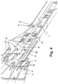
- Fig. 3 shows the funnel 4 with the cut sleeve 5 and at the rear end of the funnel 4 arranged spacer elements 8. This arrangement is still in Fig. 4 once shown from a different direction without sleeve 5. From the two figures 3 and 4 shows that 4 cylindrical projections 9 at the rear end of the funnel are provided in the through holes 10, which are located at the ends of the Spacers 8 are located, can be inserted to form a positive connection.
- the spacer elements 8 are additionally provided with a longitudinal slot 11 provided, in which a longitudinally extending web formed on the funnel 4 12 can be used, which begins directly at the projection 9 and extends in the longitudinal direction of the plastic longitudinal profile 2 extends towards the funnel opening. Through the webs 12 the non-rotatable positive connection is ensured.
- Fig. 3 and Fig. 4 show three spacer elements 8 attached to the funnel, with their other end either with a further spacer 8 or with one Busbar 3 are positively connected.
- the form closure takes place again a flying on the spacer end formed cylinder element 13, which in a corresponding hole at the associated end of the busbar 3 form-fitting is insertable.
- the spacer elements 8 have at the end a step 14 which in the assembled state, pivoting of the spacer element 8 relative to the Busbar 3 prevented.
- At least one groove 15 is provided on the spacers 8 on the side mounted inwards into the longitudinal plastic profile 2.
- the arrangement shown in FIG. 4 is in the longitudinal plastic profile 2 insertable until the rear end of the funnel 4 in a form-fitting manner Longitudinal plastic profile 2 is inserted.
- the assembly is simplified if the spacers 8 as well Busbars 3 in provided for the busbars 3 in the plastic longitudinal profile 2 Cavities 16 can be inserted.
- the busbars 3 are made of the long plastic profile 2 pushed out that they protrude from the plastic longitudinal profile 2 to them to be able to connect with the spacer elements 8 and with the funnel 4. After this The spacer elements are pre-assembled together with the busbars 3 and the funnel 4 simply inserted into the longitudinal plastic profile 2 and by means of Sleeve 5 fastened to the plastic longitudinal profile 2 with the screws 7.
- busbars 3 can also directly, that is without Spacers 8 are attached to the funnel 4.
Landscapes
- Engineering & Computer Science (AREA)
- Mechanical Engineering (AREA)
- Power Engineering (AREA)
- Transportation (AREA)
- Current-Collector Devices For Electrically Propelled Vehicles (AREA)
Abstract
Description
- Fig. 1
- eine perspektivische Darstellung der Vorrichtung mit Trichter, Muffe und Kunststofflängsprofil,
- Fig. 2
- die Darstellung gemäß Fig. 1 mit teilweise aufgeschnittener Muffe,
- Fig. 3
- den Trichter mit teilweise aufgeschnittener Muffe sowie am Trichter angeordneten Distanzelementen und
- Fig. 4
- eine Darstellung des Trichters mit Distanzelementen gemäß Fig. 3 aus einer anderen Blickrichtung, jedoch ohne Muffe.
- 1
- Schleifleitung
- 2
- Kunststofflängsprofil
- 3
- Stromschiene
- 4
- Trichter
- 5
- Muffe
- 6
- Rastelement
- 7
- Schraube
- 8
- Distanzelement
- 9
- Vorsprung
- 10
- Durchgangsbohrung
- 11
- Längsschlitz
- 12
- Steg
- 13
- Zylinderelement
- 14
- Stufe
- 15
- Nut
- 16
- Hohlraum
- 17
- Aussparung
Claims (9)
- Vorrichtung zum Ein- und Ausfahren eines Stromabnehmerwagens in ein bzw. aus einem Kunststofflängsprofil einer Stromschienen aufweisenden Schleifleitung,mit einem an einem Ende der Schleifleitung angeordneten Trichter, wobei das Kunststofflängsprofil und der Trichter mittels einer das Kunststofflängsprofil umgreifenden Muffe verbindbar sind, die vor dem Verbinden auf dem Kunststofflängsprofil frei verschiebbar ist und im verbundenen Zustand das Ende des Kunststofflängsprofils übergreift
dadurch gekennzeichnet,daß das der Innenkontur des Kunststofflängsprofils (2) angepaßte hintere Ende des Trichters (4) formschlüssig in das Kunststofflängsprofil (2) einsteckbar ist unddaß die das Kunststofflängsprofil (2) und den Trichter (4) verbindende Muffe (4) das Kunststofflängsprofil (2) formschlüssig umgreift. - Vorrichtung nach Anspruch 1,
dadurch gekennzeichnet,daß das hintere Ende des Trichters (4) mindestens teilweise verjüngt ausgebildet ist. - Vorrichtung nach einem der Ansprüche 1 oder 2,
dadurch gekennzeichnet,daß der Trichter (4) mit der Muffe (5) verrastbar ist. - Vorrichtung nach einem der Ansprüche 1 bis 3,
dadurch gekennzeichnet,daß die Muffe (5) mittels Schrauben (7) am Kunststofflangsprofil (2) befestigbar ist. - Vorrichtung nach einem der Ansprüche 1 bis 4,
dadurch gekennzeichnet,daß am hinteren Ende des Trichters (4) in das Kunststofflängsprofil (2) hineinragende elektrisch isolierende, jeweils mit einer Stromschiene (3) verbindbare Distanzelemente (8) angeordnet sind. - Vorrichtung nach Anspruch 5,
dadurch gekennzeichnet,daß jeweils zwei Distanzelemente (8) miteinander verbindbar sind. - Vorrichtung nach einem der Ansprüche 5 oder 6,
dadurch gekennzeichnet,daß die Distanzelemente (8) mit dem hinteren Ende des Trichters (4) formschlüssig verbindbar sind. - Vorrichtung nach 5 bis 7,
dadurch gekennzeichnet,daß die Distanzelemente (8) in für die Stromschienen (3) im Kunststofflängsprofil (2) vorgesehene Hohlräume (16) einschiebbar sind. - Vorrichtung nach 5 bis 8,
dadurch gekennzeichnet,daß die Distanzelemente (8) auf der nach innengerichteten Seite quer zur Längsrichtung mindestens eine Nut (15) aufweisen.
Applications Claiming Priority (2)
| Application Number | Priority Date | Filing Date | Title |
|---|---|---|---|
| DE19948108 | 1999-09-27 | ||
| DE19948108A DE19948108C2 (de) | 1999-09-27 | 1999-09-27 | Vorrichtung zum Ein- und Ausfahren eines Stromabnehmerwagens in ein bzw. aus einem Kunststofflängsprofil einer Schleifleitung |
Publications (2)
| Publication Number | Publication Date |
|---|---|
| EP1086845A1 true EP1086845A1 (de) | 2001-03-28 |
| EP1086845B1 EP1086845B1 (de) | 2005-08-17 |
Family
ID=7924667
Family Applications (1)
| Application Number | Title | Priority Date | Filing Date |
|---|---|---|---|
| EP00250319A Expired - Lifetime EP1086845B1 (de) | 1999-09-27 | 2000-09-26 | Vorrichtung zum Ein-und Ausfahren eines Stromabnehmerwagens in ein bzw aus einem Kunststofflängsprofil einer Schleifleitung |
Country Status (5)
| Country | Link |
|---|---|
| US (1) | US6425469B1 (de) |
| EP (1) | EP1086845B1 (de) |
| JP (1) | JP3933379B2 (de) |
| DE (2) | DE19948108C2 (de) |
| NO (1) | NO318573B1 (de) |
Cited By (1)
| Publication number | Priority date | Publication date | Assignee | Title |
|---|---|---|---|---|
| CN114555416A (zh) * | 2019-10-02 | 2022-05-27 | 利勃海尔矿业设备科马尔股份有限公司 | 运输件货和散装货物的工程机械的架空线路系统和工程机械 |
Families Citing this family (8)
| Publication number | Priority date | Publication date | Assignee | Title |
|---|---|---|---|---|
| US7198409B2 (en) * | 2003-06-30 | 2007-04-03 | Adc Telecommunications, Inc. | Fiber optic connector holder and method |
| JP4989315B2 (ja) * | 2007-05-29 | 2012-08-01 | パナソニック株式会社 | 絶縁トロリー線集電装置に設けられるピックアップガイド |
| JP4992590B2 (ja) * | 2007-07-24 | 2012-08-08 | パナソニック株式会社 | 絶縁トロリー線集電装置 |
| DE102009034792A1 (de) * | 2009-07-25 | 2011-01-27 | Demag Cranes & Components Gmbh | Anordnung zum Verbinden von zwei aufeinander folgenden Schleifleitungsschienen |
| SE537626C2 (sv) * | 2010-11-03 | 2015-08-18 | Hybricon Bus Systems Ab | Strömavtagare |
| US20250178485A1 (en) * | 2023-11-30 | 2025-06-05 | Caterpillar Inc. | Ramp assembly for guiding an electrical conductor system |
| DE102024114021A1 (de) * | 2024-05-17 | 2025-11-20 | Conductix-Wampfler Gmbh | Schleifleitungssystem, Stromabnehmer, Ausgabevorrichtung für ein Ladekabel, Fahrzeug, Verbindungsvorrichtung, Energieversorgungssystem sowie Verfahren zum Betrieb des Energieversorgungssystems |
| DE102024125306A1 (de) * | 2024-09-04 | 2026-03-05 | Paul Vahle Gmbh & Co. Kg | Dehnbarer Trichter |
Citations (3)
| Publication number | Priority date | Publication date | Assignee | Title |
|---|---|---|---|---|
| FR2329091A1 (fr) * | 1975-10-22 | 1977-05-20 | Nokia Oy Ab | Prise de courant a nervures de verrouillage pour installation a rail multiconducteur |
| US4416357A (en) * | 1981-08-28 | 1983-11-22 | Szysh John A | Guide structure for trolley rail and flying pickup |
| EP0938168A2 (de) * | 1998-02-19 | 1999-08-25 | MANNESMANN Aktiengesellschaft | Verbinder für zwei aufeinanderfolgende Schleifleitungsteilstücke |
-
1999
- 1999-09-27 DE DE19948108A patent/DE19948108C2/de not_active Expired - Fee Related
-
2000
- 2000-09-26 DE DE50010956T patent/DE50010956D1/de not_active Expired - Lifetime
- 2000-09-26 EP EP00250319A patent/EP1086845B1/de not_active Expired - Lifetime
- 2000-09-27 JP JP2000293273A patent/JP3933379B2/ja not_active Expired - Fee Related
- 2000-09-27 NO NO20004854A patent/NO318573B1/no not_active IP Right Cessation
- 2000-09-27 US US09/671,473 patent/US6425469B1/en not_active Expired - Lifetime
Patent Citations (3)
| Publication number | Priority date | Publication date | Assignee | Title |
|---|---|---|---|---|
| FR2329091A1 (fr) * | 1975-10-22 | 1977-05-20 | Nokia Oy Ab | Prise de courant a nervures de verrouillage pour installation a rail multiconducteur |
| US4416357A (en) * | 1981-08-28 | 1983-11-22 | Szysh John A | Guide structure for trolley rail and flying pickup |
| EP0938168A2 (de) * | 1998-02-19 | 1999-08-25 | MANNESMANN Aktiengesellschaft | Verbinder für zwei aufeinanderfolgende Schleifleitungsteilstücke |
Cited By (3)
| Publication number | Priority date | Publication date | Assignee | Title |
|---|---|---|---|---|
| CN114555416A (zh) * | 2019-10-02 | 2022-05-27 | 利勃海尔矿业设备科马尔股份有限公司 | 运输件货和散装货物的工程机械的架空线路系统和工程机械 |
| EP4021754B1 (de) * | 2019-10-02 | 2024-12-04 | Liebherr-Mining Equipment Colmar SAS | Oberleitungssystem für baumaschinen für den stück- und schüttguttransport sowie baumaschine |
| US12576751B2 (en) | 2019-10-02 | 2026-03-17 | Liebherr-Mining Equipment Colmar Sas | Overhead line system for construction machines for piece good and bulk material transport and construction machine |
Also Published As
| Publication number | Publication date |
|---|---|
| JP2001158257A (ja) | 2001-06-12 |
| US6425469B1 (en) | 2002-07-30 |
| JP3933379B2 (ja) | 2007-06-20 |
| NO20004854L (no) | 2001-03-28 |
| DE19948108A1 (de) | 2001-04-05 |
| DE19948108C2 (de) | 2003-11-20 |
| NO318573B1 (no) | 2005-04-11 |
| DE50010956D1 (de) | 2005-09-22 |
| EP1086845B1 (de) | 2005-08-17 |
| NO20004854D0 (no) | 2000-09-27 |
Similar Documents
| Publication | Publication Date | Title |
|---|---|---|
| EP0938168B1 (de) | Verbinder für zwei aufeinanderfolgende Schleifleitungsteilstücke | |
| EP2460237B1 (de) | Anordnung zum verbinden von zwei aufeinander folgenden schleifleitungsschienen | |
| DE19948108C2 (de) | Vorrichtung zum Ein- und Ausfahren eines Stromabnehmerwagens in ein bzw. aus einem Kunststofflängsprofil einer Schleifleitung | |
| EP3253640B1 (de) | Weichenverstellmechanismus mit einem zwischen den beiden stockschienen angeordneten verschluss | |
| DE4431064C2 (de) | Verbindung von Schienenprofilen | |
| DE19840642C2 (de) | Befestigungselement für einen Betätigungszug | |
| EP1455016B1 (de) | Herzstück | |
| WO2009010159A1 (de) | Stromleiste und führungsschiene für schienengeführte mobilwandelemente | |
| DE2601390A1 (de) | Eckumlenkung fuer treibstangenbeschlaege von fenstern, tueren o.dgl. | |
| EP0222067B1 (de) | Riegelvorrichtung an Treibstangenbeschlägen von Fenstern, Türen od. dgl. | |
| DE3520577C2 (de) | Elektromechanische Sicherheitskontaktleiste für kraftbetätigte Tore | |
| DE102007034930A1 (de) | Isolierprofil, Verfahren zur Montage eines Isolierprofils sowie Stromschiene | |
| EP0607954B2 (de) | Schienensystem für Flurtransportanlagen | |
| EP2878749B1 (de) | Sektionaltor mit Riegelanordnung | |
| DE9416315U1 (de) | Gehäuse für eine Überwachungseinrichtung | |
| DE2613738A1 (de) | Einrichtung zur verkeilung oder verriegelung beweglicher teile, insbesondere bei eisenbahnstreckengeraeten | |
| DE10127438C1 (de) | Seilzug-Fensterheber zum Verschieben einer Fensterscheibe mit Mitnehmer und verrastbarem Gleitelement | |
| DE8801153U1 (de) | Vorrichtung zum Verbinden einer Stromschiene mit einem an diese nicht angepaßten Adapter | |
| DE2812314C3 (de) | Fensterheber für ein schiebbares Fenster, insbesondere für Kraftfahrzeuge | |
| EP0681346B1 (de) | Elektrischer Stecker | |
| WO2026068350A1 (de) | Dehnverbindungsvorrichtung und schleifleitungssystem | |
| WO1997033290A2 (de) | Leistungsschalter mit isolierendem kontakthebelträger | |
| CH665504A5 (de) | Elektrische schaltanlage mit verriegelbarer erdung in einer zelle. | |
| DE7521931U (de) | Rahmen für Fenster, Türen u.dgl | |
| DE3524170A1 (de) | Foerderanlage mit selbstfahrenden foerderfahrzeugen |
Legal Events
| Date | Code | Title | Description |
|---|---|---|---|
| PUAI | Public reference made under article 153(3) epc to a published international application that has entered the european phase |
Free format text: ORIGINAL CODE: 0009012 |
|
| AK | Designated contracting states |
Kind code of ref document: A1 Designated state(s): DE FR GB IT NL |
|
| AX | Request for extension of the european patent |
Free format text: AL;LT;LV;MK;RO;SI |
|
| 17P | Request for examination filed |
Effective date: 20010621 |
|
| AKX | Designation fees paid |
Free format text: DE FR GB IT NL |
|
| RAP1 | Party data changed (applicant data changed or rights of an application transferred) |
Owner name: DEMAG CRANES & COMPONENTS GMBH |
|
| GRAP | Despatch of communication of intention to grant a patent |
Free format text: ORIGINAL CODE: EPIDOSNIGR1 |
|
| GRAS | Grant fee paid |
Free format text: ORIGINAL CODE: EPIDOSNIGR3 |
|
| GRAA | (expected) grant |
Free format text: ORIGINAL CODE: 0009210 |
|
| AK | Designated contracting states |
Kind code of ref document: B1 Designated state(s): DE FR GB IT NL |
|
| REG | Reference to a national code |
Ref country code: GB Ref legal event code: FG4D Free format text: NOT ENGLISH |
|
| REF | Corresponds to: |
Ref document number: 50010956 Country of ref document: DE Date of ref document: 20050922 Kind code of ref document: P |
|
| GBT | Gb: translation of ep patent filed (gb section 77(6)(a)/1977) |
Effective date: 20050923 |
|
| ET | Fr: translation filed | ||
| PLBE | No opposition filed within time limit |
Free format text: ORIGINAL CODE: 0009261 |
|
| STAA | Information on the status of an ep patent application or granted ep patent |
Free format text: STATUS: NO OPPOSITION FILED WITHIN TIME LIMIT |
|
| 26N | No opposition filed |
Effective date: 20060518 |
|
| PGFP | Annual fee paid to national office [announced via postgrant information from national office to epo] |
Ref country code: DE Payment date: 20140922 Year of fee payment: 15 |
|
| PGFP | Annual fee paid to national office [announced via postgrant information from national office to epo] |
Ref country code: GB Payment date: 20140919 Year of fee payment: 15 Ref country code: FR Payment date: 20140919 Year of fee payment: 15 |
|
| PGFP | Annual fee paid to national office [announced via postgrant information from national office to epo] |
Ref country code: NL Payment date: 20140918 Year of fee payment: 15 |
|
| PGFP | Annual fee paid to national office [announced via postgrant information from national office to epo] |
Ref country code: IT Payment date: 20140929 Year of fee payment: 15 |
|
| REG | Reference to a national code |
Ref country code: DE Ref legal event code: R119 Ref document number: 50010956 Country of ref document: DE |
|
| PG25 | Lapsed in a contracting state [announced via postgrant information from national office to epo] |
Ref country code: IT Free format text: LAPSE BECAUSE OF NON-PAYMENT OF DUE FEES Effective date: 20150926 |
|
| GBPC | Gb: european patent ceased through non-payment of renewal fee |
Effective date: 20150926 |
|
| REG | Reference to a national code |
Ref country code: NL Ref legal event code: MM Effective date: 20151001 |
|
| REG | Reference to a national code |
Ref country code: FR Ref legal event code: ST Effective date: 20160531 |
|
| PG25 | Lapsed in a contracting state [announced via postgrant information from national office to epo] |
Ref country code: DE Free format text: LAPSE BECAUSE OF NON-PAYMENT OF DUE FEES Effective date: 20160401 Ref country code: GB Free format text: LAPSE BECAUSE OF NON-PAYMENT OF DUE FEES Effective date: 20150926 |
|
| PG25 | Lapsed in a contracting state [announced via postgrant information from national office to epo] |
Ref country code: NL Free format text: LAPSE BECAUSE OF NON-PAYMENT OF DUE FEES Effective date: 20151001 Ref country code: FR Free format text: LAPSE BECAUSE OF NON-PAYMENT OF DUE FEES Effective date: 20150930 |