EP1086819A2 - Vorrichtung zum Zuführen und Ausrichten eines Druckträgers in einem Drucker - Google Patents
Vorrichtung zum Zuführen und Ausrichten eines Druckträgers in einem Drucker Download PDFInfo
- Publication number
- EP1086819A2 EP1086819A2 EP00116355A EP00116355A EP1086819A2 EP 1086819 A2 EP1086819 A2 EP 1086819A2 EP 00116355 A EP00116355 A EP 00116355A EP 00116355 A EP00116355 A EP 00116355A EP 1086819 A2 EP1086819 A2 EP 1086819A2
- Authority
- EP
- European Patent Office
- Prior art keywords
- pressure
- print carrier
- feed
- pressure element
- support surface
- Prior art date
- Legal status (The legal status is an assumption and is not a legal conclusion. Google has not performed a legal analysis and makes no representation as to the accuracy of the status listed.)
- Granted
Links
- 239000004033 plastic Substances 0.000 claims description 3
- 230000000284 resting effect Effects 0.000 claims 1
- 238000004519 manufacturing process Methods 0.000 description 4
- OKTJSMMVPCPJKN-UHFFFAOYSA-N Carbon Chemical compound [C] OKTJSMMVPCPJKN-UHFFFAOYSA-N 0.000 description 3
- 229910052799 carbon Inorganic materials 0.000 description 3
- 239000000969 carrier Substances 0.000 description 2
- 230000002349 favourable effect Effects 0.000 description 2
- 238000003780 insertion Methods 0.000 description 2
- 230000037431 insertion Effects 0.000 description 2
- 239000000463 material Substances 0.000 description 2
- 208000033999 Device damage Diseases 0.000 description 1
- 229910000831 Steel Inorganic materials 0.000 description 1
- 230000005540 biological transmission Effects 0.000 description 1
- 238000009434 installation Methods 0.000 description 1
- 239000011159 matrix material Substances 0.000 description 1
- 239000002184 metal Substances 0.000 description 1
- 239000007787 solid Substances 0.000 description 1
- 230000000087 stabilizing effect Effects 0.000 description 1
- 239000010959 steel Substances 0.000 description 1
- 239000000758 substrate Substances 0.000 description 1
Images



Classifications
-
- B—PERFORMING OPERATIONS; TRANSPORTING
- B41—PRINTING; LINING MACHINES; TYPEWRITERS; STAMPS
- B41J—TYPEWRITERS; SELECTIVE PRINTING MECHANISMS, i.e. MECHANISMS PRINTING OTHERWISE THAN FROM A FORME; CORRECTION OF TYPOGRAPHICAL ERRORS
- B41J13/00—Devices or arrangements of selective printing mechanisms, e.g. ink-jet printers or thermal printers, specially adapted for supporting or handling copy material in short lengths, e.g. sheets
- B41J13/26—Registering devices
-
- B—PERFORMING OPERATIONS; TRANSPORTING
- B41—PRINTING; LINING MACHINES; TYPEWRITERS; STAMPS
- B41J—TYPEWRITERS; SELECTIVE PRINTING MECHANISMS, i.e. MECHANISMS PRINTING OTHERWISE THAN FROM A FORME; CORRECTION OF TYPOGRAPHICAL ERRORS
- B41J11/00—Devices or arrangements of selective printing mechanisms, e.g. ink-jet printers or thermal printers, for supporting or handling copy material in sheet or web form
- B41J11/0035—Handling copy materials differing in thickness
-
- B—PERFORMING OPERATIONS; TRANSPORTING
- B41—PRINTING; LINING MACHINES; TYPEWRITERS; STAMPS
- B41J—TYPEWRITERS; SELECTIVE PRINTING MECHANISMS, i.e. MECHANISMS PRINTING OTHERWISE THAN FROM A FORME; CORRECTION OF TYPOGRAPHICAL ERRORS
- B41J13/00—Devices or arrangements of selective printing mechanisms, e.g. ink-jet printers or thermal printers, specially adapted for supporting or handling copy material in short lengths, e.g. sheets
- B41J13/10—Sheet holders, retainers, movable guides, or stationary guides
- B41J13/14—Aprons or guides for the printing section
-
- B—PERFORMING OPERATIONS; TRANSPORTING
- B41—PRINTING; LINING MACHINES; TYPEWRITERS; STAMPS
- B41J—TYPEWRITERS; SELECTIVE PRINTING MECHANISMS, i.e. MECHANISMS PRINTING OTHERWISE THAN FROM A FORME; CORRECTION OF TYPOGRAPHICAL ERRORS
- B41J3/00—Typewriters or selective printing or marking mechanisms characterised by the purpose for which they are constructed
- B41J3/28—Typewriters or selective printing or marking mechanisms characterised by the purpose for which they are constructed for printing downwardly on flat surfaces, e.g. of books, drawings, boxes, envelopes, e.g. flat-bed ink-jet printers
-
- B—PERFORMING OPERATIONS; TRANSPORTING
- B41—PRINTING; LINING MACHINES; TYPEWRITERS; STAMPS
- B41J—TYPEWRITERS; SELECTIVE PRINTING MECHANISMS, i.e. MECHANISMS PRINTING OTHERWISE THAN FROM A FORME; CORRECTION OF TYPOGRAPHICAL ERRORS
- B41J3/00—Typewriters or selective printing or marking mechanisms characterised by the purpose for which they are constructed
- B41J3/28—Typewriters or selective printing or marking mechanisms characterised by the purpose for which they are constructed for printing downwardly on flat surfaces, e.g. of books, drawings, boxes, envelopes, e.g. flat-bed ink-jet printers
- B41J3/283—Typewriters or selective printing or marking mechanisms characterised by the purpose for which they are constructed for printing downwardly on flat surfaces, e.g. of books, drawings, boxes, envelopes, e.g. flat-bed ink-jet printers on bank books or the like
Definitions
- the invention relates to a device for feeding and Align a print carrier in a printer with a Contact surface for the print carrier on at least one Side limited by a stop for the print carrier and with at least one feed and alignment element, that leads the print carrier against the stop.
- a feed and alignment device of the above Type is described in the document EP 0 448 257 A2, which a print carrier against two essentially perpendicular to each other standing stops.
- the print media can have different dimensions, Have thicknesses and / or stiffness.
- Such Print media are, for example, passbooks or from one Sheet of existing receipts.
- the transport of the print medium takes place with the help of cam wheels with which the Pressure carrier is drawn in and moved against the stops.
- the object of the invention is therefore to begin with a device Specify the type mentioned, the print media different Thickness, dimensions and rigidity on a single surface the printer positioned without the print carrier too to damage.
- the inventor has recognized that a device damage of the print carrier when positioning can be avoided if a low-friction Positioning enables and bulging of the print carrier is prevented.
- This is due to the plate-shaped Pressure element reached, the pressure surface parallel to Contact surface and immediately above the print carrier.
- the pressure area covers almost the entire contact area from, so that the print carrier also in the area of the stop is conducted safely.
- the pressure surface shows a raised edge so that not the entire pressure surface rests on the print carrier. In the area of the pressure surface, that is surrounded by the raised edge can Print carriers can thus be positioned with very little friction.
- this edge has a height of 0.2 mm, which in corresponds approximately to twice the paper thickness.
- This embodiment is particularly suitable for very thin paper, e.g. single sheets of carbon, suitable. At this Height of the edge is still ensured that the Print carrier does not bulge and is therefore damaged.
- the plate-shaped pressure element can already be due its weight stabilizing on the print carrier act, the pressure element on the print carrier lies on.
- the device can thus be moved in a simple manner adjust to the respective thickness of the print medium by the pressure element when inserting or pulling in the Print medium is pushed up by him.
- the pressure surface should be as flat as possible so that Unevenness of the print carrier not on the pressure surface get caught.
- the device is also for example stapled passbooks suitable.
- the device according to the invention is particularly for the Suitable for use in printers that line up the print carrier printing, e.g. Dot matrix printer.
- printers that line up the print carrier printing, e.g. Dot matrix printer.
- the alignment element is a role which is stored below the support surface in such a way that its size extends beyond the contact surface.
- This embodiment is particularly suitable if Print media consisting mainly of individual sheets are processed. The roll presses the paper from below against the pressure surface. This embodiment is particularly easy to manufacture. The role is easy adjust and allows a gentle transport of the print carrier.
- the pressure element at least one Has recess that with the feed and alignment flees. This is the pressure with which the feed and Alignment element the print carrier against the pressure element presses in the area above the feed and alignment element reduced and damage to the print carrier by too high pressure avoided in this area. To the contact surface pointing edges of the recess should be rounded, so that the print carrier can be guided properly becomes.
- the pressure element in a above the Support surface arranged cover frame held adjustable becomes.
- the cover frame will contaminate the Contact surface avoided.
- the counter pressure elements must be attached.
- the cover frame can in turn opposite the contact surface can be adjustable, for example by foldable is stored in the printer frame.
- the pressure element can have at least one guide pin which engages in a guide recess in the cover frame. Over the length of the guide pin, the length can also the distance to be defined by which the pressure element is adjustable perpendicular to the contact surface.
- the device according to the invention has the pressure element on its facing away from the pressure surface Side a trough-shaped recess in the one
- the weighting body can be arranged. In this way can the weight of the pressure element on the used Print carriers are optimally adapted. A pressure element that is too light can the buckling or bulging of a solid Do not prevent paper from existing print carrier and is pushed up by him.
- the weighting body can e.g. are made of metal.
- the pressure element is preferably made of a torsion-resistant Made of plastic. This makes it very easy Manufacture pressure elements, so that the invention Device also for the carbon paper already mentioned suitable is. It can also be used Simply manufacture pressure elements of any shape.
- Figure 1 shows an inventive device 10 for feeding and aligning a print carrier, not shown here.
- a printing table 12 with a support surface 14 is a first cam gear 16 with three Feed cams 18, 20 and 22 that are even over his Circumference are distributed and in pairs an angle of 120 ° lock in.
- the first cam wheel 16 has a first axis of rotation 26.
- a second cam wheel 28 with a second axis of rotation 30, the is arranged perpendicular to the first axis of rotation 26.
- the second Cam wheel 28 also has three feed cams that over its circumference is evenly distributed. Of the three feed cams of the cam wheel 28, however, are only two feed cams 32 and 34 can be seen.
- the second cams Cam wheels 28 are opposite the pull-in cams 18, 20 and 22 of the first cam wheel 16 are arranged offset by approximately 60 °. Counter pressure rollers assigned to the cam wheels 16, 28 are in Figure 1 for clarity not shown.
- a pressure plate is located above the printing table 12 36.
- a pressure surface 38 of the pressure plate 36 runs parallel to the contact surface 14 of the printing table 12.
- the pressure plate 36 has a raised edge, which is the pressure surface 38 surrounds and of which a first section 40 and a second section 42 are shown.
- a first one and a second side surface 44 or 46 of the pressure plate 36 are inclined towards the center of the pressure surface 38.
- a directional arrow 50 describes the direction of insertion of the print carrier.
- the first cam gear 16 is with the second cam gear 28 by means of a transmission, not shown here, with a Gear ratio of 1: 1 kinematically linked.
- the feed cams 18, 20 and 22 of the first cam gear 16 with respect to FIG Retraction cams 32, 34 of the second cam wheel 28 are arranged offset are alternately engaged by a feed cam of the first or the second cam wheel 16 or 28 in the Transport area 48 a.
- the print carrier is from the feed cams 18, 20, 22 of the first cam gear 16 in the direction of the arrow 50 transported.
- the feed cams 32, 34 of the second cam wheel 28 transport the print carrier vertically to arrow 50 into the drawing plane.
- Figure 2 shows the pressure plate 36, which is in a cover plate 52 is arranged. You can see three counter pressure rollers 54, 56 and 60. The axes of rotation of a first and a second Counter pressure roller 54 and 56 are perpendicular to the by the arrow 50 indicated direction of insertion of the print carrier. The axis of rotation of a third counter pressure roller 60 lies parallel to the direction arrow 50.
- a transport roller 58 is assigned to a transport axis, not shown here, which is not the print carrier here either feeds the shown print head of the printer.
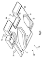
- Figure 3 shows a perspective view of the bottom the pressure plate 36. To facilitate orientation the arrow 50 is again drawn.
- the pressure plate 36 has four recesses 66, 68, 70 and 72 on. Edges 67, 69, 71 and 73 of the recesses 66, 68, 70 or 72 are rounded towards the pressure surface 38.
- On the Top of the pressure plate 36 are locking hooks 74, 76, 78 and 80 ( Figure 4) substantially perpendicular to the pressure surface 38 arranged.
- the first counterpressure roller makes contact through a first recess 66 54 the first cam gear 16.
- a second Recess 72 are the third counter-pressure roller 60 and second counter-pressure roller 56 of those assigned to them Contacted cam wheels. With the help of the locking hook 74, 76, 78 and 80, the pressure plate 36 in the cover plate 52 held.
- Figure 4 shows a perspective view of the top the pressure plate 36.
- a weighting body can be seen 82, of two pins 84 that are parallel to one another and 86 in a trough-shaped depression of the pressure plate 36 is held.
- By using different weights 82 with different thickness or from different materials can be the weight of the pressure plate 36 optimally to the rigidity of the print substrate used be adjusted.
- the length of the locking hooks 74, 76, 78 and 80 determine the length of the stroke by which the pressure plate 36 is lowered can be.
- the pressure element 36 shown is a easy and inexpensive to manufacture plastic part.
- the use of locking hooks makes it easy to get in and out Removal of the pressure element 36 and thus an uncomplicated Adapt to the material of the used one Print medium.
Landscapes
- Sheets, Magazines, And Separation Thereof (AREA)
- Handling Of Sheets (AREA)
- Registering Or Overturning Sheets (AREA)
Abstract
Description
- Figur 1
- schematisch einen Querschnitt einer erfindungsgemäßen Vorrichtung,
- Figur 2
- eine Abdeckplatte für einen Drucker mit eingehängter Andruckplatte,
- Figur 3
- eine perspektivische Ansicht der Unterseite der Andruckplatte der erfindungsgemäßen Vorrichtung, und
- Figur 4
- eine perspektivische Ansicht der Oberseite der Andruckplatte der erfindungsgemäßen Vorrichtung.
Claims (11)
- Vorrichtung zum Zuführen und Ausrichten eines Druckträgers in einem Drucker, miteiner Auflagefläche (14) für den Druckträger, die auf mindestens einer Seite durch einen Anschlag für den Druckträger begrenzt ist,mindestens einem Zuführ- und Ausrichtelement (16, 28) zu Fördern des Druckträgers gegen den Anschlag,einem oberhalb der Auflagefläche (14) diese annähernd im gesamten Zuführ- und Ausrichtbereich überdeckenden Führungsteil mit einer zur Auflagefläche (14) parallelen Führungsfläche,
dadurch gekennzeichnet,daß das Führungsteil ein auf dem Druckträger aufliegendes, senkrecht zur Auflagefläche (14) verstellbares Andruckelement (36) ist, an welchem die Führungsfläche als Andruckfläche (38) ausgebildet ist, wobei die Andruckfläche (38) von einem erhöhten Rand (40, 42) umgeben ist, welcher unmittelbar auf dem Druckträger aufliegt und die von ihm umgebene Andruckfläche (38) von dem Druckträger nur so weit beabstandet, daß in ihrem Bereich ein Aufwölben auch biegeschlaffer Druckträger verhindert bleibt und gleichzeitig eine reibungsarme Bewegung des Druckträgers sichergestellt ist. - Vorrichtung nach Anspruch 1, dadurch gekennzeichnet, daß der erhöhte Rand (40, 42) zur Auflagefläche (14) hin gewölbt ist.
- Vorrichtung nach einem der Ansprüche 1 oder 2, dadurch gekennzeichnet, daß quer zur Zuführrichtung (50) verlaufende Seitenflächen (44, 46) des Andruckelementes (36) zur Mitte der Andruckfläche (38) hin geneigt sind.
- Vorrichtung nach einem der Ansprüche 1 bis 3, dadurch gekennzeichnet, daß das Zuführ- und Ausrichtelement eine Rolle (16, 28) ist, die unterhalb der Auflagefläche (14) derart gelagert ist, daß sie mit ihrem Umfang über die Auflagefläche (14) hinausragt.
- Vorrichtung nach einem der Ansprüche 1 bis 4, dadurch gekennzeichnet, daß das Andruckelement (36) wenigstens eine Ausnehmung (66, 72) hat, die mit dem Zuführ- und Ausrichtelement (16, 28) fluchtet.
- Vorrichtung nach Anspruch 5, dadurch gekennzeichnet, daß in der Ausnehmung (66, 72) des Andruckelementes (36) ein dem Zuführ- und Ausrichtelement (16, 28) zugeordnetes Gegendruckelement (54, 56, 60) angeordnet ist.
- Vorrichtung nach Anspruch 6, dadurch gekennzeichnet, daß das Gegendruckelement ein Drehkörper (54, 56, 60) ist.
- Vorrichtung nach einem der Ansprüche 1 bis 7, dadurch gekennzeichnet, daß das Andruckelement (36) in einem oberhalb der Auflagefläche (14) angeordneten Abdeckrahmen (52) verstellbar gehalten ist.
- Vorrichtung nach Anspruch 8, dadurch gekennzeichnet, daß das Andruckelement (36) senkrecht zur Andruckfläche (38) gerichtete Rasthake n (74, 76, 78, 80) hat, die in Aussparungen des Abdeckrahmens (52) derart eingreifen, daß das Andruckelement (36) relativ zum Abdeckrahmen (52) um eine begrenzte Strecke verstellbar gehalten ist.
- Vorrichtung nach einem der Ansprüche 1 bis 9, dadurch gekennzeichnet, daß das Andruckelement (36) aus einem verwindungssteifen Kunststoff gefertigt ist.
- Vorrichtung nach einem der Ansprüche 1 bis 10, dadurch gekennzeichnet, daß das Andruckelement (36) an seiner der Andruckfläche (38) abgewandten Seite eine wannenförmige Aussparung (87) hat, in der ein Beschwerungskörper (82) angeordnet ist.
Applications Claiming Priority (2)
| Application Number | Priority Date | Filing Date | Title |
|---|---|---|---|
| DE19945343A DE19945343C2 (de) | 1999-09-22 | 1999-09-22 | Vorrichtung zum Zuführen und Ausrichten eines Druckträgers in einem Drucker |
| DE19945343 | 1999-09-22 |
Publications (3)
| Publication Number | Publication Date |
|---|---|
| EP1086819A2 true EP1086819A2 (de) | 2001-03-28 |
| EP1086819A3 EP1086819A3 (de) | 2002-01-23 |
| EP1086819B1 EP1086819B1 (de) | 2003-10-01 |
Family
ID=7922858
Family Applications (1)
| Application Number | Title | Priority Date | Filing Date |
|---|---|---|---|
| EP00116355A Expired - Lifetime EP1086819B1 (de) | 1999-09-22 | 2000-07-28 | Vorrichtung zum Zuführen und Ausrichten eines Druckträgers in einem Drucker |
Country Status (3)
| Country | Link |
|---|---|
| EP (1) | EP1086819B1 (de) |
| DE (2) | DE19945343C2 (de) |
| ES (1) | ES2208195T3 (de) |
Family Cites Families (5)
| Publication number | Priority date | Publication date | Assignee | Title |
|---|---|---|---|---|
| JPS6166672A (ja) * | 1984-09-11 | 1986-04-05 | Oki Electric Ind Co Ltd | 記帳機 |
| US4909374A (en) * | 1986-01-13 | 1990-03-20 | Pitney Bowes Inc. | Flat article direction changing device |
| IT1240137B (it) * | 1990-03-20 | 1993-11-27 | Olivetti & Co Spa | Dispositivo di avanzamento e allineamento di fogli per una stampante |
| US5844584A (en) * | 1996-12-31 | 1998-12-01 | Pitney Bowes Inc. | Print head stop mechanism for a postage meter |
| US5913627A (en) * | 1997-12-11 | 1999-06-22 | Pitney Bowes Inc. | Guide and support structure for a mailing machine |
-
1999
- 1999-09-22 DE DE19945343A patent/DE19945343C2/de not_active Expired - Fee Related
-
2000
- 2000-07-28 EP EP00116355A patent/EP1086819B1/de not_active Expired - Lifetime
- 2000-07-28 DE DE50003888T patent/DE50003888D1/de not_active Expired - Lifetime
- 2000-07-28 ES ES00116355T patent/ES2208195T3/es not_active Expired - Lifetime
Also Published As
| Publication number | Publication date |
|---|---|
| ES2208195T3 (es) | 2004-06-16 |
| EP1086819A3 (de) | 2002-01-23 |
| DE19945343A1 (de) | 2001-04-05 |
| DE50003888D1 (de) | 2003-11-06 |
| EP1086819B1 (de) | 2003-10-01 |
| DE19945343C2 (de) | 2002-04-11 |
Similar Documents
| Publication | Publication Date | Title |
|---|---|---|
| DE69804377T2 (de) | Bogentrenner | |
| DE69500216T2 (de) | Vorrichtung zum seitlichen Ausrichten von flachen Gegenständen auf einem Tisch | |
| DE29903717U1 (de) | Vorrichtung zur Bereitstellung eines Vorrats von Einzelblättern ungleicher Dicke | |
| DE4431488C3 (de) | Bogenführung im Anleger einer Bogendruckmaschine | |
| DE3427514A1 (de) | Vorrichtung an einem einzelblattabzug fuer drucker und dergleichen | |
| EP1086819B1 (de) | Vorrichtung zum Zuführen und Ausrichten eines Druckträgers in einem Drucker | |
| DE4315511B4 (de) | Sauggreifer für eine Bogenübergabetrommel | |
| DE3524010C1 (de) | Papierfuehrung fuer Druckeinrichtungen mit in Abhaengigkeit von der Breite verschieblichen Papierfuehrungselementen | |
| DE2738855A1 (de) | Vorrichtung zur papierfuehrung in druckgeraeten, insbesondere bei daten- und fernschreibmaschinen | |
| DE3247341C2 (de) | ||
| DE2913594C2 (de) | Vorrichtung zum Vereinzeln des jeweils obersten blattförmigen Aufzeichnungsträgers von einem Stapel | |
| DE2127757A1 (de) | Papierzuführer zum Vereinzeln von Papierblättern eines Stapels | |
| DE69609217T2 (de) | Medientransport bei einem Tintenstrahldrucker | |
| DE69606386T2 (de) | Vorlagenausricht- und zufuhr- vorrichtung | |
| DE68911564T2 (de) | Vorrichtung zum Sichern des Flachliegens eines Blattes und der Druckspalteinstellung. | |
| DE2419571C3 (de) | Vorrichtung zur Niederhaltung des Randbereiches von Blattmaterial auf einem Transportband | |
| DE19623116A1 (de) | Blatteinzug für einen Drucker | |
| DE291298C (de) | ||
| DE69015082T2 (de) | Differentialreibantrieb für Datenträger. | |
| EP0280060B1 (de) | Transportvorrichtung für Blattmaterial | |
| DE9000255U1 (de) | Leiteinrichtung | |
| DE102004060646A1 (de) | Bogenpositioniervorrichtung einer Bogenzuführeinrichtung von einer Druckerpresse | |
| DE102023112475A1 (de) | Stapelwender zum Wenden von Stapeln sowie Maschine zur Be- und/oder Verarbeitung Substratbogen | |
| WO1987005996A1 (fr) | Dispositif de prise pour faire avancer la bande de materiau dans des tables traçantes | |
| EP0812684A2 (de) | Druckmaschine mit einem Bogentransportband |
Legal Events
| Date | Code | Title | Description |
|---|---|---|---|
| PUAI | Public reference made under article 153(3) epc to a published international application that has entered the european phase |
Free format text: ORIGINAL CODE: 0009012 |
|
| AK | Designated contracting states |
Kind code of ref document: A2 Designated state(s): AT BE CH CY DE DK ES FI FR GB GR IE IT LI LU MC NL PT SE Kind code of ref document: A2 Designated state(s): DE ES FR GB IT |
|
| AX | Request for extension of the european patent |
Free format text: AL;LT;LV;MK;RO;SI |
|
| 17P | Request for examination filed |
Effective date: 20010221 |
|
| PUAL | Search report despatched |
Free format text: ORIGINAL CODE: 0009013 |
|
| AK | Designated contracting states |
Kind code of ref document: A3 Designated state(s): AT BE CH CY DE DK ES FI FR GB GR IE IT LI LU MC NL PT SE |
|
| AX | Request for extension of the european patent |
Free format text: AL;LT;LV;MK;RO;SI |
|
| RIC1 | Information provided on ipc code assigned before grant |
Free format text: 7B 41J 13/00 A, 7B 41J 13/10 B, 7B 41J 13/26 B |
|
| AKX | Designation fees paid |
Free format text: DE ES FR GB IT |
|
| RAP1 | Party data changed (applicant data changed or rights of an application transferred) |
Owner name: WINCOR NIXDORF INTERNATIONAL GMBH |
|
| GRAH | Despatch of communication of intention to grant a patent |
Free format text: ORIGINAL CODE: EPIDOS IGRA |
|
| GRAH | Despatch of communication of intention to grant a patent |
Free format text: ORIGINAL CODE: EPIDOS IGRA |
|
| GRAA | (expected) grant |
Free format text: ORIGINAL CODE: 0009210 |
|
| AK | Designated contracting states |
Kind code of ref document: B1 Designated state(s): DE ES FR GB IT |
|
| REG | Reference to a national code |
Ref country code: GB Ref legal event code: FG4D Free format text: NOT ENGLISH |
|
| REG | Reference to a national code |
Ref country code: IE Ref legal event code: FG4D Free format text: GERMAN |
|
| REF | Corresponds to: |
Ref document number: 50003888 Country of ref document: DE Date of ref document: 20031106 Kind code of ref document: P |
|
| GBT | Gb: translation of ep patent filed (gb section 77(6)(a)/1977) |
Effective date: 20031229 |
|
| REG | Reference to a national code |
Ref country code: ES Ref legal event code: FG2A Ref document number: 2208195 Country of ref document: ES Kind code of ref document: T3 |
|
| REG | Reference to a national code |
Ref country code: IE Ref legal event code: FD4D |
|
| ET | Fr: translation filed | ||
| PLBE | No opposition filed within time limit |
Free format text: ORIGINAL CODE: 0009261 |
|
| STAA | Information on the status of an ep patent application or granted ep patent |
Free format text: STATUS: NO OPPOSITION FILED WITHIN TIME LIMIT |
|
| 26N | No opposition filed |
Effective date: 20040702 |
|
| PGFP | Annual fee paid to national office [announced via postgrant information from national office to epo] |
Ref country code: ES Payment date: 20080723 Year of fee payment: 9 |
|
| PGFP | Annual fee paid to national office [announced via postgrant information from national office to epo] |
Ref country code: FR Payment date: 20080718 Year of fee payment: 9 |
|
| PGFP | Annual fee paid to national office [announced via postgrant information from national office to epo] |
Ref country code: GB Payment date: 20080723 Year of fee payment: 9 |
|
| GBPC | Gb: european patent ceased through non-payment of renewal fee |
Effective date: 20090728 |
|
| REG | Reference to a national code |
Ref country code: FR Ref legal event code: ST Effective date: 20100331 |
|
| PG25 | Lapsed in a contracting state [announced via postgrant information from national office to epo] |
Ref country code: FR Free format text: LAPSE BECAUSE OF NON-PAYMENT OF DUE FEES Effective date: 20090731 |
|
| PG25 | Lapsed in a contracting state [announced via postgrant information from national office to epo] |
Ref country code: GB Free format text: LAPSE BECAUSE OF NON-PAYMENT OF DUE FEES Effective date: 20090728 |
|
| REG | Reference to a national code |
Ref country code: ES Ref legal event code: FD2A Effective date: 20090729 |
|
| PG25 | Lapsed in a contracting state [announced via postgrant information from national office to epo] |
Ref country code: ES Free format text: LAPSE BECAUSE OF NON-PAYMENT OF DUE FEES Effective date: 20090729 |
|
| PGFP | Annual fee paid to national office [announced via postgrant information from national office to epo] |
Ref country code: DE Payment date: 20160720 Year of fee payment: 17 Ref country code: IT Payment date: 20160720 Year of fee payment: 17 |
|
| REG | Reference to a national code |
Ref country code: DE Ref legal event code: R119 Ref document number: 50003888 Country of ref document: DE |
|
| PG25 | Lapsed in a contracting state [announced via postgrant information from national office to epo] |
Ref country code: DE Free format text: LAPSE BECAUSE OF NON-PAYMENT OF DUE FEES Effective date: 20180201 |
|
| PG25 | Lapsed in a contracting state [announced via postgrant information from national office to epo] |
Ref country code: IT Free format text: LAPSE BECAUSE OF NON-PAYMENT OF DUE FEES Effective date: 20170728 |