EP1085550A2 - Installationsschalter - Google Patents
Installationsschalter Download PDFInfo
- Publication number
- EP1085550A2 EP1085550A2 EP00117968A EP00117968A EP1085550A2 EP 1085550 A2 EP1085550 A2 EP 1085550A2 EP 00117968 A EP00117968 A EP 00117968A EP 00117968 A EP00117968 A EP 00117968A EP 1085550 A2 EP1085550 A2 EP 1085550A2
- Authority
- EP
- European Patent Office
- Prior art keywords
- terminal
- circuit breaker
- plug
- installation switch
- conductor wire
- Prior art date
- Legal status (The legal status is an assumption and is not a legal conclusion. Google has not performed a legal analysis and makes no representation as to the accuracy of the status listed.)
- Withdrawn
Links
- 239000004020 conductor Substances 0.000 claims abstract description 18
- 238000009434 installation Methods 0.000 claims abstract description 9
- 210000002105 tongue Anatomy 0.000 claims description 4
- 241000722921 Tulipa gesneriana Species 0.000 description 8
- 238000003780 insertion Methods 0.000 description 3
- 230000037431 insertion Effects 0.000 description 3
- WABPQHHGFIMREM-UHFFFAOYSA-N lead(0) Chemical compound [Pb] WABPQHHGFIMREM-UHFFFAOYSA-N 0.000 description 3
- 238000000034 method Methods 0.000 description 1
- 238000010791 quenching Methods 0.000 description 1
- 230000000171 quenching effect Effects 0.000 description 1
Images
Classifications
-
- H—ELECTRICITY
- H01—ELECTRIC ELEMENTS
- H01H—ELECTRIC SWITCHES; RELAYS; SELECTORS; EMERGENCY PROTECTIVE DEVICES
- H01H71/00—Details of the protective switches or relays covered by groups H01H73/00 - H01H83/00
- H01H71/08—Terminals; Connections
- H01H71/082—Connections between juxtaposed circuit breakers
-
- H—ELECTRICITY
- H02—GENERATION; CONVERSION OR DISTRIBUTION OF ELECTRIC POWER
- H02B—BOARDS, SUBSTATIONS OR SWITCHING ARRANGEMENTS FOR THE SUPPLY OR DISTRIBUTION OF ELECTRIC POWER
- H02B1/00—Frameworks, boards, panels, desks, casings; Details of substations or switching arrangements
- H02B1/20—Bus-bar or other wiring layouts, e.g. in cubicles, in switchyards
- H02B1/205—Bus-bar or other wiring layouts, e.g. in cubicles, in switchyards for connecting electrical apparatus mounted side by side on a rail
-
- H—ELECTRICITY
- H01—ELECTRIC ELEMENTS
- H01R—ELECTRICALLY-CONDUCTIVE CONNECTIONS; STRUCTURAL ASSOCIATIONS OF A PLURALITY OF MUTUALLY-INSULATED ELECTRICAL CONNECTING ELEMENTS; COUPLING DEVICES; CURRENT COLLECTORS
- H01R31/00—Coupling parts supported only by co-operation with counterpart
- H01R31/08—Short-circuiting members for bridging contacts in a counterpart
- H01R31/085—Short circuiting bus-strips
-
- H—ELECTRICITY
- H01—ELECTRIC ELEMENTS
- H01R—ELECTRICALLY-CONDUCTIVE CONNECTIONS; STRUCTURAL ASSOCIATIONS OF A PLURALITY OF MUTUALLY-INSULATED ELECTRICAL CONNECTING ELEMENTS; COUPLING DEVICES; CURRENT COLLECTORS
- H01R4/00—Electrically-conductive connections between two or more conductive members in direct contact, i.e. touching one another; Means for effecting or maintaining such contact; Electrically-conductive connections having two or more spaced connecting locations for conductors and using contact members penetrating insulation
- H01R4/28—Clamped connections, spring connections
- H01R4/30—Clamped connections, spring connections utilising a screw or nut clamping member
-
- H—ELECTRICITY
- H01—ELECTRIC ELEMENTS
- H01R—ELECTRICALLY-CONDUCTIVE CONNECTIONS; STRUCTURAL ASSOCIATIONS OF A PLURALITY OF MUTUALLY-INSULATED ELECTRICAL CONNECTING ELEMENTS; COUPLING DEVICES; CURRENT COLLECTORS
- H01R4/00—Electrically-conductive connections between two or more conductive members in direct contact, i.e. touching one another; Means for effecting or maintaining such contact; Electrically-conductive connections having two or more spaced connecting locations for conductors and using contact members penetrating insulation
- H01R4/28—Clamped connections, spring connections
- H01R4/48—Clamped connections, spring connections utilising a spring, clip, or other resilient member
Definitions
- the invention relates to an installation switch, in particular a circuit breaker or residual current circuit breaker according to the preamble of claim 1.
- connection technology for circuit breakers or residual current circuit breakers was in the past only a screwing technique, whereby a clamp was provided was in which a busbar arrangement and a conductor wire simultaneously with one Clamping screw were fixed.
- Terminal arrangement chosen so that the Busbar arrangement - seen from the front of the switchgear the conductor wire is clamped. This means that threading the conductor wire into the clamp arrangement creates difficulties insofar as the threading point or the receiving opening is covered by the busbar arrangement. Here is incorrect connections frequently occurred.
- a clamping device is known become one at a terminal lug of the busbar assembly pluggable intermediate part inserted into a plug-in terminal in the switchgear and thus is screwed.
- the circuit breaker with the intermediate part is on the Busbar attached.
- the object of the invention is therefore a terminal arrangement for an installation switch to create the type mentioned, in which the problems of the known Arrangements are avoided.
- this object is achieved in that a for the conductor wire Screw terminals and for cross wiring in the form of a busbar arrangement a plug-in terminal are provided, the plug-in terminal closer to the fastening side is located as the screw terminal.
- the plug-in terminal can at least have two resiliently pressed tongues, between which the connecting lug can be inserted into the busbar arrangement.
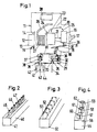
- a commercially available circuit breaker 10 has a fastening side 11 in which a recess 12 is provided with which the circuit breaker on a Hat profile mounting rail 13 is fixed.
- the recess 12 has one Wall a fixed nose 14 and on the opposite wall movable nose 15, which is under the pressure of a spring against the top-hat rail 13 is pressed when the circuit breaker 10 on the top-hat rail 13 is mounted.
- the circuit breaker 10 also has a switch lock 16 on which a switch toggle 17 is connected to actuate the circuit breaker 10.
- a trigger serves an electromagnetic release 18, which should switch off short circuits, and an overcurrent release 19 in the form of a bimetallic strip, which according to line 20 on the Switch lock acts.
- the electromagnetic trigger 18 also acts on the Switch lock on according to line 21, and one of the trigger 18 associated anchor strikes on a contact lever 22 in the direction of arrow 23, whereby a contact point 24 is opened.
- the electromagnetic release 18 also acts via the action line 21 on the key switch, whereby the movable contact lever according to line of action 25 is permanently placed in the off position.
- a simple Frame clamp 30 with a clamp frame 31 and a clamping screw 32 includes; there is an opening between the clamping screw 32 and the clamping frame 31 33 is provided, into which a conductor wire 34 can be inserted with its stripped end and can be clamped by means of the clamping screw 32.
- a push-through opening 35 is located at switch 10 a push-through opening 35; the push-through opening with which the conductor 34 inside the simple screw terminal 31 can be inserted is not shown in FIG. 1.
- the simple box clamp 30 is located in the area or near the front 36.
- connection arrangement 29 belongs in the area of the fastening surface 11 a clamping tulip 37 (also called tulip contact 37), the two resilient flags 38 and 39, into which a busbar arrangement 40 can be inserted, which is shown in more detail in FIG. 2.
- 2 is the busbar arrangement known per se and has a busbar housing 41 in which one of the Number of phases corresponding number of ribbon conductors 42, 43 and 44, on which terminal lugs 45, 46, 47 are formed, which in the corresponding Tulip contacts 37 can each be used a circuit breaker.
- a three-pole arrangement there are three circuit breakers according to FIG.
- the connecting lug 45 engages in the clamping tulip 37 of the first Miniature circuit breaker, the terminal lug 46 in the corresponding clamping tulip next circuit breaker and the connecting lug in the corresponding Clamp tulip of the third circuit breaker.
- the arrangement according to FIG. 3 shows similar busbar arrangement 50, in which the Terminal lugs 51, 52 are not, as in the case of the busbar arrangement Fig. 2, are in one plane, but in which the connecting lugs 51, 52nd run perpendicular to the longitudinal extension and parallel to each other.
- Corresponding the connecting tulip 37 would be formed therein by two spring elements which have an opening form between them and parallel to the plane of the drawing, i.e. parallel to the Broadside level of the circuit breaker 10 run.
- busbar housing 56 busbars with resilient cylinder contacts 57 to 59, a longitudinal slot 60, to achieve a spring characteristic, 61 and 62 is provided.
- a corresponding circuit breaker 10 is then located cylindrical socket contact or pin contact.
- the clamping tulip 37 is connected to the box terminal 30 by a connecting conductor 65 connected so that electrical contact between the two terminals 30th and 37 is achieved.
- a stranded conductor 66 can then connect to the connecting conductor 65, which supplies the current to the individual components.
- the connecting conductor 65 can be rigid and thus the terminal arrangement 29 with Box clamp 30 and clamp 37 a preassembled unit.
Landscapes
- Engineering & Computer Science (AREA)
- Power Engineering (AREA)
- Breakers (AREA)
- Distribution Board (AREA)
- Connections Arranged To Contact A Plurality Of Conductors (AREA)
Abstract
Description
- Fig. 1
- eine Einsicht in einen Leitungsschutzschalter,
- Fig. 2 bis 4
- drei unterschiedliche Sammelschienenanordnungen, die in den Leitungsschutzschalter gemäß Fig. 1 eingesetzt werden können.
Claims (5)
- Installationsschalter insbesondere Leitungsschutzschalter oder Fehlerstromschutzschalter mit einer Anschlußstelle für eine Querverdrahtung und einen Leiterdraht, dadurch gekennzeichnet, daß für den Leiterdraht eine Schraubklemme und für die Querverdrahtung in Form einer Sammelschienenanordnung eine Steckklemme vorgesehen sind, wobei die Steckklemme näher zur Befestigungsseite hin als die Schraubklemme gelegen ist.
- Installationsschalter nach Anspruch 1, dadurch gekennzeichnet, daß die Steckklemme wenigstens zwei federnd gegeneinandergedrückte Zungen besitzt, zwischen die eine Anschlußfahne an der Sammelschienenanordnung einschiebbar ist.
- Installationsschalter nach Anspruch 2, dadurch gekennzeichnet, daß die Zungen einen Aufnahmeraum bilden, der parallel zur Befestigungsfläche zur zugehörigen Schmalseite hin offen ist.
- Installationsschalter nach Anspruch 2, dadurch gekennzeichnet, daß die federnd gegeneinandergedrückgte Zungen eine Aufnahmeöffnung bilden, die parallel zur Breitseite des Installationsschalters verläuft und zur zugehörigen Schmalseite hin offen ist.
- Installationsschalter nach Anspruch 1, dadurch gekennzeichnet, daß die Steckklemme ein Steckerstift oder eine Steckerbuchse bildet.
Applications Claiming Priority (4)
| Application Number | Priority Date | Filing Date | Title |
|---|---|---|---|
| DE29916001U DE29916001U1 (de) | 1999-09-13 | 1999-09-13 | Installationsschalter |
| DE29916001U | 1999-09-13 | ||
| DE19950995 | 1999-10-22 | ||
| DE19950995A DE19950995A1 (de) | 1999-09-13 | 1999-10-22 | Installationsschalter |
Publications (2)
| Publication Number | Publication Date |
|---|---|
| EP1085550A2 true EP1085550A2 (de) | 2001-03-21 |
| EP1085550A3 EP1085550A3 (de) | 2002-08-28 |
Family
ID=26055341
Family Applications (1)
| Application Number | Title | Priority Date | Filing Date |
|---|---|---|---|
| EP00117968A Withdrawn EP1085550A3 (de) | 1999-09-13 | 2000-08-22 | Installationsschalter |
Country Status (4)
| Country | Link |
|---|---|
| EP (1) | EP1085550A3 (de) |
| HU (1) | HUP0003559A3 (de) |
| PL (1) | PL342509A1 (de) |
| SG (1) | SG90168A1 (de) |
Cited By (3)
| Publication number | Priority date | Publication date | Assignee | Title |
|---|---|---|---|---|
| EP1432001A1 (de) * | 2002-12-20 | 2004-06-23 | Hager Electro | Elektrisches Gerät, beispielsweise modulares elektrisches Gerät mit einem zweiteiligen Gehäuse |
| EP1353350A3 (de) * | 2002-04-12 | 2005-02-02 | ABB PATENT GmbH | Hilfsschalter |
| CN108962692A (zh) * | 2018-08-28 | 2018-12-07 | 温州聚创电气科技有限公司 | 接线框装配设备 |
Family Cites Families (6)
| Publication number | Priority date | Publication date | Assignee | Title |
|---|---|---|---|---|
| DE7813854U1 (de) * | 1978-05-08 | 1979-10-11 | Licentia Patent-Verwaltungs-Gmbh, 6000 Frankfurt | Mit einem mehrpoligen Leitungsschutzschalter kombinierter Fehlerstromschutzschalter |
| EP0434964B1 (de) * | 1989-11-27 | 1994-04-13 | Bticino S.P.A. | Bauelementensatz zum gleizeitigen elektrischen Verbinden einer Mehrzahl von modularen Selbstschaltern |
| GB2247351B (en) * | 1990-08-21 | 1995-03-01 | Crabtree Electrical Ind Ltd | Improvements relating to the mounting of circuit breakers |
| US5439396A (en) * | 1993-09-28 | 1995-08-08 | At&T Corp. | Adapter for circuit breaker and assemblage thereof |
| FR2768260B1 (fr) * | 1997-09-05 | 1999-10-22 | Schneider Electric Sa | Dispositif d'assemblage et de liaison electrique d'appareils electriques modulaires de puissance tels des disjoncteurs |
| DE19744977A1 (de) * | 1997-10-13 | 1999-04-15 | Abb Patent Gmbh | Adapter zum Verbinden einer Sammelschienenanordnung mit der Eingangsklemme eines Hauptleitungsschutzschalters |
-
2000
- 2000-08-22 EP EP00117968A patent/EP1085550A3/de not_active Withdrawn
- 2000-09-11 HU HU0003559A patent/HUP0003559A3/hu unknown
- 2000-09-13 PL PL00342509A patent/PL342509A1/xx not_active Application Discontinuation
- 2000-09-13 SG SG200005257A patent/SG90168A1/en unknown
Cited By (3)
| Publication number | Priority date | Publication date | Assignee | Title |
|---|---|---|---|---|
| EP1353350A3 (de) * | 2002-04-12 | 2005-02-02 | ABB PATENT GmbH | Hilfsschalter |
| EP1432001A1 (de) * | 2002-12-20 | 2004-06-23 | Hager Electro | Elektrisches Gerät, beispielsweise modulares elektrisches Gerät mit einem zweiteiligen Gehäuse |
| CN108962692A (zh) * | 2018-08-28 | 2018-12-07 | 温州聚创电气科技有限公司 | 接线框装配设备 |
Also Published As
| Publication number | Publication date |
|---|---|
| PL342509A1 (en) | 2001-03-26 |
| EP1085550A3 (de) | 2002-08-28 |
| HUP0003559A2 (hu) | 2002-03-28 |
| SG90168A1 (en) | 2002-07-23 |
| HU0003559D0 (en) | 2000-09-11 |
| HUP0003559A3 (en) | 2002-11-28 |
Similar Documents
| Publication | Publication Date | Title |
|---|---|---|
| DE102008017245B4 (de) | Steckadapter für ein elektrisches Schaltgerät | |
| EP1412957B1 (de) | Schaltgerät mit einheitlichem schalterbaustein | |
| EP2546856B1 (de) | Leiste für NH-Sicherungen | |
| DE102006049773B4 (de) | Modulares Installationsschaltgerät | |
| EP1898436B1 (de) | Steckvorrichtung zum Stecken auf eine elektrische Schaltvorrichtung | |
| DE2645325A1 (de) | Eingangsverbinder fuer telefonvermittlungen | |
| DE10152347C1 (de) | Schaltgerät mit adaptiertem mehrphasigem Sammelschienensystem | |
| DE10003266C2 (de) | Stromkreisunterbrechereinrichtung | |
| DE19950995A1 (de) | Installationsschalter | |
| DE102006006050B4 (de) | Sicherungsleiste sowie Adapterleiste mit Kontaktstiften und der Sicherungsleiste | |
| EP1990879B1 (de) | Einzelaufstellungsträger zur Befestigung eines Überlastrelais | |
| EP1085550A2 (de) | Installationsschalter | |
| DE10344735B4 (de) | Elektrisches Installationsgerät | |
| DE10146503A1 (de) | Elektrische Installationsverteilung | |
| DE9312380U1 (de) | Federkraftklemme | |
| DE102023124074A1 (de) | Baukastensystem zur Ausbildung einer elektrischen Verteileranordnung, Verteilerklemmenmodul eines solchen Baukastens und elektrische Verteileranordnung | |
| EP0080646B1 (de) | Fassung für ein Miniaturrelais | |
| EP4068329B1 (de) | Einrichtung zur anordnung an stromsammelschienen aufweisend ein schaltgerät und eine elektronikkomponente | |
| DE4438215C2 (de) | NH-Sicherungs-Lasttrennschalter mit Sicherungsüberwachung | |
| EP1353350B1 (de) | Hilfsschalter | |
| EP2489100A1 (de) | Schraubklemme mit abdeckung und installationsschaltgerät | |
| EP1787358B1 (de) | Strom-einspeisemodul mit käfig-zugfederklemmen | |
| DE102016122437B4 (de) | Kontaktierungsvorrichtung | |
| DE10224976A1 (de) | Verbindungsbaugruppe zum elektrischen Verbinden eines elektrischen Grundschaltgeräts mit einem elektrischen Zusatzschaltgerät | |
| EP2202848A1 (de) | Verbindungsanordnung mit einem elektrischen Gerät |
Legal Events
| Date | Code | Title | Description |
|---|---|---|---|
| PUAI | Public reference made under article 153(3) epc to a published international application that has entered the european phase |
Free format text: ORIGINAL CODE: 0009012 |
|
| AK | Designated contracting states |
Kind code of ref document: A2 Designated state(s): AT BE CH CY DE DK ES FI FR GB GR IE IT LI LU MC NL PT SE |
|
| AX | Request for extension of the european patent |
Free format text: AL;LT;LV;MK;RO;SI PAYMENT 20000831 |
|
| RAP1 | Party data changed (applicant data changed or rights of an application transferred) |
Owner name: ABB PATENT GMBH |
|
| PUAL | Search report despatched |
Free format text: ORIGINAL CODE: 0009013 |
|
| AK | Designated contracting states |
Kind code of ref document: A3 Designated state(s): AT BE CH CY DE DK ES FI FR GB GR IE IT LI LU MC NL PT SE |
|
| AX | Request for extension of the european patent |
Free format text: AL;LT;LV;MK;RO;SI PAYMENT 20000831 |
|
| 17P | Request for examination filed |
Effective date: 20020913 |
|
| AKX | Designation fees paid |
Designated state(s): AT BE CH CY DE DK ES FI FR GB GR IE IT LI LU MC NL PT SE |
|
| AXX | Extension fees paid |
Extension state: SI Payment date: 20000831 |
|
| STAA | Information on the status of an ep patent application or granted ep patent |
Free format text: STATUS: THE APPLICATION IS DEEMED TO BE WITHDRAWN |
|
| 18D | Application deemed to be withdrawn |
Effective date: 20040302 |