EP1432001A1 - Elektrisches Gerät, beispielsweise modulares elektrisches Gerät mit einem zweiteiligen Gehäuse - Google Patents
Elektrisches Gerät, beispielsweise modulares elektrisches Gerät mit einem zweiteiligen Gehäuse Download PDFInfo
- Publication number
- EP1432001A1 EP1432001A1 EP02360377A EP02360377A EP1432001A1 EP 1432001 A1 EP1432001 A1 EP 1432001A1 EP 02360377 A EP02360377 A EP 02360377A EP 02360377 A EP02360377 A EP 02360377A EP 1432001 A1 EP1432001 A1 EP 1432001A1
- Authority
- EP
- European Patent Office
- Prior art keywords
- electrical device
- block
- electrical
- truncated
- removable
- Prior art date
- Legal status (The legal status is an assumption and is not a legal conclusion. Google has not performed a legal analysis and makes no representation as to the accuracy of the status listed.)
- Granted
Links
Images


Classifications
-
- H—ELECTRICITY
- H01—ELECTRIC ELEMENTS
- H01H—ELECTRIC SWITCHES; RELAYS; SELECTORS; EMERGENCY PROTECTIVE DEVICES
- H01H71/00—Details of the protective switches or relays covered by groups H01H73/00 - H01H83/00
- H01H71/08—Terminals; Connections
- H01H71/082—Connections between juxtaposed circuit breakers
-
- H—ELECTRICITY
- H01—ELECTRIC ELEMENTS
- H01H—ELECTRIC SWITCHES; RELAYS; SELECTORS; EMERGENCY PROTECTIVE DEVICES
- H01H11/00—Apparatus or processes specially adapted for the manufacture of electric switches
- H01H11/0006—Apparatus or processes specially adapted for the manufacture of electric switches for converting electric switches
- H01H11/0031—Apparatus or processes specially adapted for the manufacture of electric switches for converting electric switches for allowing different types or orientation of connections to contacts
- H01H2011/0037—Apparatus or processes specially adapted for the manufacture of electric switches for converting electric switches for allowing different types or orientation of connections to contacts with removable or replaceable terminal blocks
Definitions
- the present invention relates to electrical devices of the type so-called modular differential circuit breaker, block or switch comprising a insulating housing, and designed to be mounted on a rail or any other support attachment, attached to other electrical devices of the same type to constitute an electrical distribution circuit.
- the invention does not relate exclusively devices qualified as modular, which in principle obey a fairly precise sizing, but it finds ground with these privileged and majority application.
- these devices have a housing that integrates functional means enabling them to fulfill the electrical objective which is assigned, said housing further having fixing means and support on the rail or support.
- the boxes finally include input and output connection means opening into their faces perpendicular to both the rail and the abutment plane, for the connection of at least one individual conductor or part of a bridging bar suitable for being also connected to adjacent devices contiguous.
- the modular electrical devices on each rail are used in both single and multi-phase electrical circuits, allowing in each case multiple possibilities of configurations and / or solutions of connection.
- the distribution of neutral and / or phases, in particular, is often performed using rigid bridging bars with regularly spaced connection tabs, intended to be inserted into the connectors of the various electrical devices arranged on the rail.
- a bridging bar therefore does not allow recourse to devices with connecting devices spaced one step apart different, that is to say electrical devices integrated in a housing whose width represents a multiple or a sub-multiple of that of a module.
- this invention provides a solution which allows a decorrelation between the pitch of connection of the external distribution on the one hand and the step of the devices installed on the other hand, and which significantly reduces the number and the dimensions of the connection elements to current modular boxes.
- the invention also makes it possible to conserve the compatibility with distribution solutions that are already in place, and in particular the supply of modular devices by bridging bars rigid and by individual conductors.
- the system of the invention leads to a lower production costs by pooling certain functions, when it applies to more than one paired device.
- Said invention consists in fact of an electrical appliance of the type modular circuit breaker, block or switch, comprising a box insulation intended to be mounted on a rail or any other fixing support, attached to other electrical devices to form a distribution circuit electric, and for this purpose comprising input connection means and outlet opening into its faces perpendicular to said rail and to the plane connection, for the connection of at least one individual conductor or forming part of a bridging bar suitable for also being connected to any adjacent device attached, and it is mainly characterized in that the housing is divided into two parts that can be connected and separated mechanically and electrically, forming a truncated housing and a removable block, the latter being able to cooperate with either a single box, or shareable between at least two truncated boxes joined together, and containing the connection means input allowing connection to the distribution circuit of the truncated housings to which said block is connected, as well as means for downstream electrical connection to the truncated box (es).
- an electrical appliance of the type modular circuit breaker, block
- the volume initially allocated to the housing of electrical appliances classics, essentially modular, is therefore divided into two parts one of which has the functional core which performs the function (s) electric, and the other is in fact a distribution accessory which ensures electrical connection or interfacing between at least one conductor external and said functional nucleus.
- the invention takes on its full meaning when the removable block is shared between several boxes, the latter being therefore all truncated to be able integrate the block by plugging in, as this results in a significant reduction in the number of external power supply conductors for the phases and / or for the neutral, the supply being done only once for the removable block, instead of an individual connection for each device as it is in existing configurations.
- the input connection means are spaced at a pitch p 1 corresponding to the modular pitch of the connecting tabs of the bridging bars , and the length of said removable block is an integer multiple of this step p 1 .
- the second condition to be fulfilled to obtain compatibility with existing products and their traditional connection mode is in the bridging level, which must of course be equivalent to that of the housings traditional to respect the bypass continuity.
- Respect for the spacing of the connection openings and the level of bridging allows in particular the use of conventional bridging bars, when the device of the invention is integrated, on a mounting rail, between electrical appliances fitted with conventional boxes.
- Each removable block therefore comprises a single set of means for input connection for each phase and / or neutral, the existence of a set of connection means for each phase and for the neutral depending on the electrical configuration presented by the box (es) truncated to which the block is connected. So there can be only one set connection means for a single phase, or two sets for a phase and neutral, etc. This greatly simplifies the input connection, as well as the space it entails, the individual connections with the functional cores of electrical devices being taken care of downstream of the removable block. As will be seen in more detail below, it is these downstream connections, the pitch of which is completely uncorrelated from that of the connections above, which make said individual connections.
- This structure allows a great flexibility of operation, that either in the initial design of the distribution board, for the maintenance or replacement of products if necessary. This flexibility is not only reflected in the initial design work of the table, but also in the increased ease and speed of interventions on site in the event of a problem, dismantling for testing or changing a product being for example almost instantaneous.
- connection tabs unused bridging bar When an electrical device according to the invention, that is to say having a removable block supporting input connection functions located placed side by side between conventional modular devices, themselves connected by a bridging comb, and that the removable block has a length which appreciably exceeds the zone in which the connection means, it is necessary to provide for the management of the connection tabs unused bridging bar.
- the block includes means for housing said tabs, in its face into which the input connection means open, at less in areas lacking these means.
- New devices with removable block according to the invention can therefore be joined on one or two of their sides to classic modular devices, without any restrictions.
- said means of accommodation consist of at least a straight groove extending parallel to the rail or other support fixation.
- the connection tabs of the bridging blade (s) are then inserted into the slot (s) located at their bridging level in the removable block, without having an electrical connection to inside the block.
- said groove can be replaced by alveoli.
- the downstream electrical connection means are spaced by a regular step p 2 which is, as already mentioned, not necessarily equal to the step p 1 above. It is therefore at this level that the decorrelation takes place between the external step, at input, and the internal step, downstream.
- the step p 2 separating the downstream quick connection means is a multiple or a sub-multiple of the step p 1 . This is particularly the case when the removable block of the invention must be used to interface double or triple truncated modules.
- the removable block comprises downstream means for quick electrical connection to the truncated box (es), i.e. pluggable and preferably removable without tools.
- Said quick connection means consist for example of conductive tabs cooperating with blades also spring conductive so as to establish an electrical connection between the block removable and the truncated case (s).
- This structure is easy to implement and provides a secure electrical connection.
- the tongues are also protected by IP2X type.
- each tab is surrounded by a conductive wall of shape designed to fit into a correspondingly shaped orifice in the truncated box at the outlet of the spring blade with which it cooperates.
- the tabs are attached to the block removable and the leaf spring connectors are integrated into the truncated housing.
- the removable block and the truncated boxes to which it is fixed can be pre-assembled in a compact block, then mounted on the rail or support.
- extraction of a single truncated case, and its replacement can easily be implemented by inserting a new box truncated on the tab or tabs which protrude from the block attached to the others truncated boxes mounted on the rail or support.
- the removable block allows a second level of design and realization of a part of the distribution circuit, which is totally independent of the input connections arranged outside the volumes of the traditional complete boxes.
- the choice of the removable block directs in a some measure the configuration of the circuit downstream of this block (width), but the user keeps the choice, in particular according to the spacing of the means of downstream connection, of a number of possible electrical circuits, which depends on the selected devices.
- removable blocks serve in particular as connection accessories integrated into the complete volumes of the boxes, and they therefore release, between two adjacent rows, a significant space because they allow significantly limit the number of external connection conductors.
- the space between two rows of adjacent devices being very limited, and little conducive to manipulation occurring during the development of circuits, or during replacement during maintenance operations, is thus used to optimally with the structure of the invention.
- the removable block may include means for fixing to the rail or to the mounting bracket which are also shared.
- At least one latch for fixing to the rail can for example be mounted therein so that it can slide on said part.
- the removable block cooperates with several housings different electrical devices, and depending on its length, we may not plan only one or two latches. Their number does not correspond in any event more necessarily to the number of truncated boxes of modular devices attached downstream of the removable block, and in most cases remains below this number.
- the removable unit may include a differential switch controlling the electrical devices connected to the block, and dispensing with provide a specific box for this function.
- the removable blocks may be fitted with a surge arrester, a voltage indicator, a phase balance indicator, etc.
- the truncated case (2) integrates the functions essential electrical components of the electrical appliance (1).
- said truncated housing (2) and the removable block (3) constitute a electrical device whose external dimensions recreate the volume of traditional modular electrical appliances.
- the removable block (3) develops from the front (4) of the product up to its sole (5), and over the entire width of the device, and it includes therefore the face into which the input connection means open.
- the fitting of the removable block (3) on the truncated case (2) is in particular made possible by the complementarity of the forms opposite these two parts.
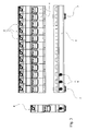
- Figure 2 shows an example of a series of functional kernels, represented by their truncated housing (2), intended to cooperate with a single block removable (3), therefore of a length adapted to the sum of the module widths (2).
- the group consisting of truncated boxes (2) connected to the removable block (3) is then intended to be attached, on a rail support, to a conventional modular device (6).
- the configuration shown is intended to be used in a three-phase circuit, and the means of there are therefore three input connections (8).
- These means in this case are traditional clamping screw cages, said screws being accessible via orifices (9) arranged in the upper part of the block (3) in the extension of the facade (4).
- Connection means downstream, intended to electrically connect said block (3) to truncated housings (2) are not visible in this figure. They are intended to fit into the holes (11) shown on the short side sides of said truncated housings (2) facing the block (3).
- the removable block (3) intended to cooperate with 12 boxes of width corresponding to a module, has only two latches (7) for fixing to the mounting rail.
- the fixing notches (appearing especially in Figure 1) located in the truncated housing, at the sole (5), there are 12, one per product, and only cooperate with two latches (7). This obviously leads to financial gain, by saving parts and simplifying assembly, which is not negligible with reference to the quantity of devices produced.
- FIG. 3 having a configuration identical to that of FIG. 2, makes more visible the type of downstream electrical connection used to make to the connection of the removable block (3) to the truncated boxes (2).
- This is in the occurrence of circular-looking studs (10) intended to be inserted in the aforementioned holes (11), which will be described in more detail with reference to the figure 5.
- These circular studs (10) only have a mechanical function of connection and guidance, the electrical connection being made by a tongue arranged inside said studs (10).
- Figure 5 shows the removable block (3) used in Figures 2 to 4, but in an opposite orientation.
- the studs (10) surround many tabs electrical connection (12), which are designed to be inserted in blades spring arranged in the truncated housings (2), and emerging at the holes (11).
- FIG. 6 constitutes a possible variant of the connection system downstream of Figure 5, according to which the blades (12) are this time inserted between two parallel low walls (13, 13 '). These low walls (13, 13 '), as much that the cylindrical studs (10) aim to protect the user against any contact accidental on the tabs, according to the safety standards in force.
- the pitch of the means of downstream connection is equal to the pitch of the input connection means (8). He ... not of course this is a very special case, the main purpose of the block removable (3) being to achieve a decorrelation between the upstream pitch of input connection means and the downstream step. This objective must be fulfilled without however break compatibility with modular electrical devices existing, regardless of the size of the removable block (3).
Landscapes
- Coupling Device And Connection With Printed Circuit (AREA)
- Connections Arranged To Contact A Plurality Of Conductors (AREA)
- Details Of Connecting Devices For Male And Female Coupling (AREA)
Priority Applications (3)
| Application Number | Priority Date | Filing Date | Title |
|---|---|---|---|
| EP02360377A EP1432001B1 (de) | 2002-12-20 | 2002-12-20 | Elektrisches Gerät, beispielsweise modulares elektrisches Gerät mit einem zweiteiligen Gehäuse |
| DE60227086T DE60227086D1 (de) | 2002-12-20 | 2002-12-20 | Elektrisches Gerät, beispielsweise modulares elektrisches Gerät mit einem zweiteiligen Gehäuse |
| AT02360377T ATE398334T1 (de) | 2002-12-20 | 2002-12-20 | Elektrisches gerät, beispielsweise modulares elektrisches gerät mit einem zweiteiligen gehäuse |
Applications Claiming Priority (1)
| Application Number | Priority Date | Filing Date | Title |
|---|---|---|---|
| EP02360377A EP1432001B1 (de) | 2002-12-20 | 2002-12-20 | Elektrisches Gerät, beispielsweise modulares elektrisches Gerät mit einem zweiteiligen Gehäuse |
Publications (2)
| Publication Number | Publication Date |
|---|---|
| EP1432001A1 true EP1432001A1 (de) | 2004-06-23 |
| EP1432001B1 EP1432001B1 (de) | 2008-06-11 |
Family
ID=32338220
Family Applications (1)
| Application Number | Title | Priority Date | Filing Date |
|---|---|---|---|
| EP02360377A Expired - Lifetime EP1432001B1 (de) | 2002-12-20 | 2002-12-20 | Elektrisches Gerät, beispielsweise modulares elektrisches Gerät mit einem zweiteiligen Gehäuse |
Country Status (3)
| Country | Link |
|---|---|
| EP (1) | EP1432001B1 (de) |
| AT (1) | ATE398334T1 (de) |
| DE (1) | DE60227086D1 (de) |
Cited By (3)
| Publication number | Priority date | Publication date | Assignee | Title |
|---|---|---|---|---|
| EP1962320A1 (de) * | 2007-02-22 | 2008-08-27 | Hager-Electro SAS | Elektrisches Gerät in Blockmodulbauweise |
| WO2017021623A1 (fr) | 2015-07-31 | 2017-02-09 | Hager-Electro Sas | Ensemble de boîtiers d'appareils electriques mecaniquement et electriquement relies entre eux |
| FR3094581A1 (fr) * | 2019-03-26 | 2020-10-02 | Schneider Electric Industries Sas | Dispositif d’alimentation et de raccordement electrique d’un ensemble d’appareils modulaires montes sur un support de montage. |
Citations (7)
| Publication number | Priority date | Publication date | Assignee | Title |
|---|---|---|---|---|
| DE1563832A1 (de) * | 1966-09-07 | 1970-03-05 | Stotz Kontakt Gmbh | Mehrpoliger Fehlerstromschutzschalter |
| EP0691669A1 (de) * | 1994-07-06 | 1996-01-10 | Schneider Electric Sa | Hilfseinheit, insbesondere Zustandsanzeige für Schutzschalter |
| FR2779269A1 (fr) * | 1998-05-29 | 1999-12-03 | Hager Electro | Dispositif de couplage de deux elements electriques modulaires accoles |
| EP1014414A1 (de) * | 1998-12-23 | 2000-06-28 | Schneider Electric Industries SA | Elektrisches Gerät wie ein Leistungsschalter oder ein moduläre Schalter |
| EP1085550A2 (de) * | 1999-09-13 | 2001-03-21 | ABBPATENT GmbH | Installationsschalter |
| EP1160944A1 (de) * | 2000-05-31 | 2001-12-05 | Schneider Electric Industries SA | Modulares elektrisches Gerät mit Schnappverbindung an isoliertem Verteiler |
| DE10120677A1 (de) * | 2001-04-27 | 2002-11-14 | Siemens Ag | Modulares Reiheneinbaugerät |
-
2002
- 2002-12-20 AT AT02360377T patent/ATE398334T1/de not_active IP Right Cessation
- 2002-12-20 EP EP02360377A patent/EP1432001B1/de not_active Expired - Lifetime
- 2002-12-20 DE DE60227086T patent/DE60227086D1/de not_active Expired - Lifetime
Patent Citations (7)
| Publication number | Priority date | Publication date | Assignee | Title |
|---|---|---|---|---|
| DE1563832A1 (de) * | 1966-09-07 | 1970-03-05 | Stotz Kontakt Gmbh | Mehrpoliger Fehlerstromschutzschalter |
| EP0691669A1 (de) * | 1994-07-06 | 1996-01-10 | Schneider Electric Sa | Hilfseinheit, insbesondere Zustandsanzeige für Schutzschalter |
| FR2779269A1 (fr) * | 1998-05-29 | 1999-12-03 | Hager Electro | Dispositif de couplage de deux elements electriques modulaires accoles |
| EP1014414A1 (de) * | 1998-12-23 | 2000-06-28 | Schneider Electric Industries SA | Elektrisches Gerät wie ein Leistungsschalter oder ein moduläre Schalter |
| EP1085550A2 (de) * | 1999-09-13 | 2001-03-21 | ABBPATENT GmbH | Installationsschalter |
| EP1160944A1 (de) * | 2000-05-31 | 2001-12-05 | Schneider Electric Industries SA | Modulares elektrisches Gerät mit Schnappverbindung an isoliertem Verteiler |
| DE10120677A1 (de) * | 2001-04-27 | 2002-11-14 | Siemens Ag | Modulares Reiheneinbaugerät |
Cited By (3)
| Publication number | Priority date | Publication date | Assignee | Title |
|---|---|---|---|---|
| EP1962320A1 (de) * | 2007-02-22 | 2008-08-27 | Hager-Electro SAS | Elektrisches Gerät in Blockmodulbauweise |
| WO2017021623A1 (fr) | 2015-07-31 | 2017-02-09 | Hager-Electro Sas | Ensemble de boîtiers d'appareils electriques mecaniquement et electriquement relies entre eux |
| FR3094581A1 (fr) * | 2019-03-26 | 2020-10-02 | Schneider Electric Industries Sas | Dispositif d’alimentation et de raccordement electrique d’un ensemble d’appareils modulaires montes sur un support de montage. |
Also Published As
| Publication number | Publication date |
|---|---|
| ATE398334T1 (de) | 2008-07-15 |
| DE60227086D1 (de) | 2008-07-24 |
| EP1432001B1 (de) | 2008-06-11 |
Similar Documents
| Publication | Publication Date | Title |
|---|---|---|
| EP0775375B1 (de) | Anspeisenetzwerk mit niedrigem übersprechen | |
| EP1376638B1 (de) | Elektromagnetischer Schutz und Steuereinheit | |
| FR2904737A1 (fr) | Ensemble de distribution pour installation electrique | |
| EP1432001B1 (de) | Elektrisches Gerät, beispielsweise modulares elektrisches Gerät mit einem zweiteiligen Gehäuse | |
| EP0726614A1 (de) | Zusammensetzbare elektrische Schnittstellenvorrichtung | |
| EP0524115B1 (de) | Kontaktleister, insbesondere für Telefon- oder Datenleitungen | |
| EP0484243B1 (de) | Schwachstromverbinder für die Vorverdrahtung eines Gebäudes | |
| EP0425393A1 (de) | Vorrichtung zur Durchführung von Baugruppen zur Steuerung und Schutz elektrischer Niederspannungsschaltungen | |
| EP3641063A1 (de) | Vorrichtung zur stromzuführung und zur elektrischen verbindung eines kontaktschalters mit einer anordnung von modularen elektrischen geräten, die nebeneinander auf derselben montagehalterung montiert sind | |
| FR2928041A1 (fr) | Prise d'alimentation electrique pour une goulotte ou analogue, utilisable individuellement ou en association. | |
| FR3039698B1 (fr) | Ensemble de boitiers d'appareils electriques mecaniquement et electriquement relies entre eux | |
| EP1916744B1 (de) | Vorrichtung zur Brückenbildung auf zwei Verbindungshöhen, die eine Verbindung zwischen Abzweigungsanschlüssen ermöglicht | |
| EP2408068B1 (de) | Konfigurierbare Überbrückungsvorrichtung | |
| EP1713152B1 (de) | Steuerungssystem für elektrische Geräte der Mittelspannungstechnik | |
| FR2807578A1 (fr) | Montant de chassis formant simultanement conduit de distribution et de repartition de l'energie electrique a differents niveaux de branchement d'appareillages | |
| EP1107363B1 (de) | Monopolarer Modularerverteiler | |
| FR2725071A1 (fr) | Interrupteur differentiel associe a un ou plusieurs elements de protection de circuits tels des coupe-circuits a fusibles ou disjoncteurs | |
| FR3060223A1 (fr) | Compteur modulaire a alimenter par un peigne d’alimentation et ensemble electrique comportant un tel compteur ainsi qu’un dispositif de verrouillage du peigne en position de connexion | |
| EP2482385A1 (de) | Elektrische Geräte, die mit Haltemitteln für eine Überbrückungsvorrichtung ausgestattet sind | |
| FR3020506A1 (fr) | Borne de connexion electrique multi-conducteurs | |
| FR2800927A1 (fr) | Repartiteur de puissance electrique pour tiroir enfichable et tiroir enfichable | |
| FR3094581A1 (fr) | Dispositif d’alimentation et de raccordement electrique d’un ensemble d’appareils modulaires montes sur un support de montage. | |
| FR2990571A1 (fr) | Ensemble d'extremite pour ensemble de distribution pour installation electrique | |
| FR2863410A1 (fr) | Connecteur electrique filtre modulaire | |
| EP1726019B1 (de) | Überspannungsschutzvorrichtung reduzierter grösse im gleichtakt-/differentialmodus |
Legal Events
| Date | Code | Title | Description |
|---|---|---|---|
| PUAI | Public reference made under article 153(3) epc to a published international application that has entered the european phase |
Free format text: ORIGINAL CODE: 0009012 |
|
| AK | Designated contracting states |
Kind code of ref document: A1 Designated state(s): AT BE BG CH CY CZ DE DK EE ES FI FR GB GR IE IT LI LU MC NL PT SE SI SK TR |
|
| AX | Request for extension of the european patent |
Extension state: AL LT LV MK RO |
|
| 17P | Request for examination filed |
Effective date: 20040831 |
|
| 17Q | First examination report despatched |
Effective date: 20041213 |
|
| AKX | Designation fees paid |
Designated state(s): AT BE BG CH CY CZ DE DK EE ES FI FR GB GR IE IT LI LU MC NL PT SE SI SK TR |
|
| GRAP | Despatch of communication of intention to grant a patent |
Free format text: ORIGINAL CODE: EPIDOSNIGR1 |
|
| GRAS | Grant fee paid |
Free format text: ORIGINAL CODE: EPIDOSNIGR3 |
|
| GRAA | (expected) grant |
Free format text: ORIGINAL CODE: 0009210 |
|
| AK | Designated contracting states |
Kind code of ref document: B1 Designated state(s): AT BE BG CH CY CZ DE DK EE ES FI FR GB GR IE IT LI LU MC NL PT SE SI SK TR |
|
| REG | Reference to a national code |
Ref country code: GB Ref legal event code: FG4D Free format text: NOT ENGLISH |
|
| REG | Reference to a national code |
Ref country code: CH Ref legal event code: EP |
|
| REF | Corresponds to: |
Ref document number: 60227086 Country of ref document: DE Date of ref document: 20080724 Kind code of ref document: P |
|
| REG | Reference to a national code |
Ref country code: IE Ref legal event code: FG4D Free format text: LANGUAGE OF EP DOCUMENT: FRENCH |
|
| PG25 | Lapsed in a contracting state [announced via postgrant information from national office to epo] |
Ref country code: FI Free format text: LAPSE BECAUSE OF FAILURE TO SUBMIT A TRANSLATION OF THE DESCRIPTION OR TO PAY THE FEE WITHIN THE PRESCRIBED TIME-LIMIT Effective date: 20080611 Ref country code: SI Free format text: LAPSE BECAUSE OF FAILURE TO SUBMIT A TRANSLATION OF THE DESCRIPTION OR TO PAY THE FEE WITHIN THE PRESCRIBED TIME-LIMIT Effective date: 20080611 |
|
| PG25 | Lapsed in a contracting state [announced via postgrant information from national office to epo] |
Ref country code: AT Free format text: LAPSE BECAUSE OF FAILURE TO SUBMIT A TRANSLATION OF THE DESCRIPTION OR TO PAY THE FEE WITHIN THE PRESCRIBED TIME-LIMIT Effective date: 20080611 Ref country code: NL Free format text: LAPSE BECAUSE OF FAILURE TO SUBMIT A TRANSLATION OF THE DESCRIPTION OR TO PAY THE FEE WITHIN THE PRESCRIBED TIME-LIMIT Effective date: 20080611 |
|
| NLV1 | Nl: lapsed or annulled due to failure to fulfill the requirements of art. 29p and 29m of the patents act | ||
| PG25 | Lapsed in a contracting state [announced via postgrant information from national office to epo] |
Ref country code: PT Free format text: LAPSE BECAUSE OF FAILURE TO SUBMIT A TRANSLATION OF THE DESCRIPTION OR TO PAY THE FEE WITHIN THE PRESCRIBED TIME-LIMIT Effective date: 20081111 Ref country code: ES Free format text: LAPSE BECAUSE OF FAILURE TO SUBMIT A TRANSLATION OF THE DESCRIPTION OR TO PAY THE FEE WITHIN THE PRESCRIBED TIME-LIMIT Effective date: 20080922 Ref country code: SE Free format text: LAPSE BECAUSE OF FAILURE TO SUBMIT A TRANSLATION OF THE DESCRIPTION OR TO PAY THE FEE WITHIN THE PRESCRIBED TIME-LIMIT Effective date: 20080911 Ref country code: CZ Free format text: LAPSE BECAUSE OF FAILURE TO SUBMIT A TRANSLATION OF THE DESCRIPTION OR TO PAY THE FEE WITHIN THE PRESCRIBED TIME-LIMIT Effective date: 20080611 |
|
| REG | Reference to a national code |
Ref country code: IE Ref legal event code: FD4D |
|
| PG25 | Lapsed in a contracting state [announced via postgrant information from national office to epo] |
Ref country code: SK Free format text: LAPSE BECAUSE OF FAILURE TO SUBMIT A TRANSLATION OF THE DESCRIPTION OR TO PAY THE FEE WITHIN THE PRESCRIBED TIME-LIMIT Effective date: 20080611 |
|
| PLBE | No opposition filed within time limit |
Free format text: ORIGINAL CODE: 0009261 |
|
| STAA | Information on the status of an ep patent application or granted ep patent |
Free format text: STATUS: NO OPPOSITION FILED WITHIN TIME LIMIT |
|
| PG25 | Lapsed in a contracting state [announced via postgrant information from national office to epo] |
Ref country code: EE Free format text: LAPSE BECAUSE OF FAILURE TO SUBMIT A TRANSLATION OF THE DESCRIPTION OR TO PAY THE FEE WITHIN THE PRESCRIBED TIME-LIMIT Effective date: 20080611 Ref country code: IE Free format text: LAPSE BECAUSE OF FAILURE TO SUBMIT A TRANSLATION OF THE DESCRIPTION OR TO PAY THE FEE WITHIN THE PRESCRIBED TIME-LIMIT Effective date: 20080611 Ref country code: DK Free format text: LAPSE BECAUSE OF FAILURE TO SUBMIT A TRANSLATION OF THE DESCRIPTION OR TO PAY THE FEE WITHIN THE PRESCRIBED TIME-LIMIT Effective date: 20080611 Ref country code: BG Free format text: LAPSE BECAUSE OF FAILURE TO SUBMIT A TRANSLATION OF THE DESCRIPTION OR TO PAY THE FEE WITHIN THE PRESCRIBED TIME-LIMIT Effective date: 20080911 |
|
| 26N | No opposition filed |
Effective date: 20090312 |
|
| BERE | Be: lapsed |
Owner name: HAGER ELECTRO Effective date: 20081231 |
|
| PG25 | Lapsed in a contracting state [announced via postgrant information from national office to epo] |
Ref country code: MC Free format text: LAPSE BECAUSE OF NON-PAYMENT OF DUE FEES Effective date: 20081231 |
|
| REG | Reference to a national code |
Ref country code: CH Ref legal event code: PL |
|
| GBPC | Gb: european patent ceased through non-payment of renewal fee |
Effective date: 20081220 |
|
| PG25 | Lapsed in a contracting state [announced via postgrant information from national office to epo] |
Ref country code: BE Free format text: LAPSE BECAUSE OF NON-PAYMENT OF DUE FEES Effective date: 20081231 |
|
| PG25 | Lapsed in a contracting state [announced via postgrant information from national office to epo] |
Ref country code: LI Free format text: LAPSE BECAUSE OF NON-PAYMENT OF DUE FEES Effective date: 20081231 Ref country code: CH Free format text: LAPSE BECAUSE OF NON-PAYMENT OF DUE FEES Effective date: 20081231 |
|
| PG25 | Lapsed in a contracting state [announced via postgrant information from national office to epo] |
Ref country code: GB Free format text: LAPSE BECAUSE OF NON-PAYMENT OF DUE FEES Effective date: 20081220 |
|
| PG25 | Lapsed in a contracting state [announced via postgrant information from national office to epo] |
Ref country code: LU Free format text: LAPSE BECAUSE OF NON-PAYMENT OF DUE FEES Effective date: 20081220 Ref country code: CY Free format text: LAPSE BECAUSE OF FAILURE TO SUBMIT A TRANSLATION OF THE DESCRIPTION OR TO PAY THE FEE WITHIN THE PRESCRIBED TIME-LIMIT Effective date: 20080611 |
|
| PG25 | Lapsed in a contracting state [announced via postgrant information from national office to epo] |
Ref country code: TR Free format text: LAPSE BECAUSE OF FAILURE TO SUBMIT A TRANSLATION OF THE DESCRIPTION OR TO PAY THE FEE WITHIN THE PRESCRIBED TIME-LIMIT Effective date: 20080611 |
|
| PG25 | Lapsed in a contracting state [announced via postgrant information from national office to epo] |
Ref country code: GR Free format text: LAPSE BECAUSE OF FAILURE TO SUBMIT A TRANSLATION OF THE DESCRIPTION OR TO PAY THE FEE WITHIN THE PRESCRIBED TIME-LIMIT Effective date: 20080912 |
|
| REG | Reference to a national code |
Ref country code: FR Ref legal event code: PLFP Year of fee payment: 14 |
|
| REG | Reference to a national code |
Ref country code: FR Ref legal event code: PLFP Year of fee payment: 15 |
|
| PGFP | Annual fee paid to national office [announced via postgrant information from national office to epo] |
Ref country code: FR Payment date: 20161130 Year of fee payment: 15 |
|
| PGFP | Annual fee paid to national office [announced via postgrant information from national office to epo] |
Ref country code: IT Payment date: 20161206 Year of fee payment: 15 |
|
| PGFP | Annual fee paid to national office [announced via postgrant information from national office to epo] |
Ref country code: DE Payment date: 20161223 Year of fee payment: 15 |
|
| REG | Reference to a national code |
Ref country code: DE Ref legal event code: R119 Ref document number: 60227086 Country of ref document: DE |
|
| REG | Reference to a national code |
Ref country code: FR Ref legal event code: ST Effective date: 20180831 |
|
| PG25 | Lapsed in a contracting state [announced via postgrant information from national office to epo] |
Ref country code: DE Free format text: LAPSE BECAUSE OF NON-PAYMENT OF DUE FEES Effective date: 20180703 Ref country code: IT Free format text: LAPSE BECAUSE OF NON-PAYMENT OF DUE FEES Effective date: 20171220 Ref country code: FR Free format text: LAPSE BECAUSE OF NON-PAYMENT OF DUE FEES Effective date: 20180102 |