EP0484243B1 - Schwachstromverbinder für die Vorverdrahtung eines Gebäudes - Google Patents
Schwachstromverbinder für die Vorverdrahtung eines Gebäudes Download PDFInfo
- Publication number
- EP0484243B1 EP0484243B1 EP91402918A EP91402918A EP0484243B1 EP 0484243 B1 EP0484243 B1 EP 0484243B1 EP 91402918 A EP91402918 A EP 91402918A EP 91402918 A EP91402918 A EP 91402918A EP 0484243 B1 EP0484243 B1 EP 0484243B1
- Authority
- EP
- European Patent Office
- Prior art keywords
- connector
- further characterized
- base
- receptacle according
- conductors
- Prior art date
- Legal status (The legal status is an assumption and is not a legal conclusion. Google has not performed a legal analysis and makes no representation as to the accuracy of the status listed.)
- Expired - Lifetime
Links
- 239000004020 conductor Substances 0.000 claims description 61
- 238000006073 displacement reaction Methods 0.000 claims description 10
- 230000000295 complement effect Effects 0.000 claims description 6
- 238000003780 insertion Methods 0.000 description 3
- 230000037431 insertion Effects 0.000 description 3
- 240000008042 Zea mays Species 0.000 description 2
- 238000012550 audit Methods 0.000 description 2
- 239000002991 molded plastic Substances 0.000 description 2
- 238000004026 adhesive bonding Methods 0.000 description 1
- 230000005540 biological transmission Effects 0.000 description 1
- 238000010276 construction Methods 0.000 description 1
- 238000009795 derivation Methods 0.000 description 1
- 238000005315 distribution function Methods 0.000 description 1
- 239000000428 dust Substances 0.000 description 1
- 230000007613 environmental effect Effects 0.000 description 1
- 238000009413 insulation Methods 0.000 description 1
- 230000010354 integration Effects 0.000 description 1
- 238000007726 management method Methods 0.000 description 1
- 238000004519 manufacturing process Methods 0.000 description 1
- 239000002184 metal Substances 0.000 description 1
- 230000004048 modification Effects 0.000 description 1
- 238000012986 modification Methods 0.000 description 1
- 230000003287 optical effect Effects 0.000 description 1
- 238000009877 rendering Methods 0.000 description 1
- 230000035939 shock Effects 0.000 description 1
- 238000003466 welding Methods 0.000 description 1
Images


Classifications
-
- H—ELECTRICITY
- H01—ELECTRIC ELEMENTS
- H01R—ELECTRICALLY-CONDUCTIVE CONNECTIONS; STRUCTURAL ASSOCIATIONS OF A PLURALITY OF MUTUALLY-INSULATED ELECTRICAL CONNECTING ELEMENTS; COUPLING DEVICES; CURRENT COLLECTORS
- H01R31/00—Coupling parts supported only by co-operation with counterpart
- H01R31/06—Intermediate parts for linking two coupling parts, e.g. adapter
-
- H—ELECTRICITY
- H02—GENERATION; CONVERSION OR DISTRIBUTION OF ELECTRIC POWER
- H02G—INSTALLATION OF ELECTRIC CABLES OR LINES, OR OF COMBINED OPTICAL AND ELECTRIC CABLES OR LINES
- H02G3/00—Installations of electric cables or lines or protective tubing therefor in or on buildings, equivalent structures or vehicles
Definitions
- the present invention relates to a weak current socket for building pre-wiring.
- the pre-wiring in low currents of a building consists in providing it, if possible as of its construction, with a network of communication cables and sockets which can adapt for a significant period (for example fifty years) to the connection of all types of equipment having to communicate with each other or with the outside, such as telephones, computer or office workstations, automated building management systems, image transmission devices, etc., at any point in the building.
- connection sockets each with at least one connector.
- An important technical problem is the standardization of sockets, given the wide variety of low current connectors available on the market: it is estimated that there are more than twenty different types of connectors, and other connectors will certainly appear in the years to come.
- WO-A-88/02 190 illustrates a typical example of the latter solution.
- the intermediate connector is specific to a particular manufacturer and specifically intended to be used as an intermediate connector in a socket. Therefore, it is produced in relatively small series, and it is relatively expensive.
- the socket is specifically adapted to receive interface connectors of the so-called "modular jack" type, which are small. And since said interface connectors are located inside the socket housing, it would not be possible to replace them with more bulky interface connectors. Therefore, if it is necessary to connect an appliance with a more bulky connector to the pre-wired network, the whole plug must be dismantled and replaced by a plug fitted with the desired connector.
- the socket disclosed in document WO-A-88/02 190 must be dismantled when an interface connector has to be replaced, which can lead to damage to said socket.
- the present invention aims to solve these technical problems.
- the base includes double self-stripping contacts and conductors connected to said first intermediate connector, each self-stripping contact being adapted to receive a conductor connected to the first intermediate connector and a conductor of the cable.
- the base includes triple self-stripping contacts and conductors connected to said first intermediate connector, each self-stripping contact being adapted to receive a conductor connected to the first intermediate connector and a cable conductor and each self-contact stripping also being adapted to receive a conductor in diversion to another taken.
- the adapter box has a front part separate from the rear part of said adapter box and fixed to said rear part, and said rear part is independent of said electrical device.
- the socket adapter box can also include double self-stripping contacts to which are connected on the one hand conductors connected to the second intermediate connector, and on the other hand conductors connected to said electrical device.
- the cable comprises a screen drain
- said outlet comprises conduction means which connect the screen drain of the cable to the electrical device.
- the base and the adapter box are assembled by screwing, and said conduction means are a screw, a corresponding socket and a self-stripping contact in contact with said socket, the screen drain of the cable being connected to said self-stripping contact and a conductor connecting the screw to said electrical device.
- the base may include a concealment flap of the first intermediate connector.
- said first and second intermediate connectors are standard connectors, for example of the "modular jack” type.
- one of said first and second intermediate connectors is a male connector of the "modular jack" type comprising an elastic locking tab and said socket comprises means for retracting said elastic locking tongue and rendering it inoperative , so that said first and second intermediate connectors can be uncoupled by simple relative sliding.
- one of said first and second intermediate connectors is a male connector of the "modular jack” type normally comprising an elastic locking tab and modified so as not to include said elastic locking tab, so that said first and second intermediate connectors can be uncoupled by simple relative sliding.
- the electrical device which comprises the adapter box and which communicates with the pre-wired network can be a connector accessible from the outside, a cable or a sensor.
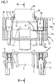
- the weak socket according to the invention consists of a base 1 and an adapter box 2. These two parts are generally made of molded plastic, but could be made otherwise without leaving the frame of the present invention.
- the base 1 is generally fitted into a connection box (not shown) fixed to the wall or on a terminal, or placed in a technical floor.
- the fixing of the base 1 to the connection box can be carried out for example using elastic snap-on lugs 3 of the base 1.
- the base 1 has a front face 4, which is only visible from the outside when the base 1 is snapped onto the connection box, and which is provided with an opening 5 occupied by an intermediate connector 6, here of the type female, which extends towards the inside of the connection box from the front face 4, and which is fixed to the base 1, for example by snap-fastening using elastic arms 7.
- the connector intermediate 6 can be molded directly into the front face 4 of the base 1.
- the connector 6 is a standard communication connector, that is to say a male or female connector meeting a widely used standard or type and adapted to be connected to an external device via a complementary connector connected to said device.
- a standard communication connector that is to say a male or female connector meeting a widely used standard or type and adapted to be connected to an external device via a complementary connector connected to said device.
- the intermediate connector 6 could be of a type generally called “modular jack", sometimes “RJ 45" or “miniature jack”, which has been adopted by the "US Federal Communication Commission” as a standard connector for connecting telephone equipment. telephone lines (Code of Federal Regulations - 47 CFR, part 68, subpart F - Connectors). This type of connector has also been chosen in ISO 8877 for access to the digital network with service integration (ISDN). It generally has 4, 6 or 8 contacts. In the embodiment of the invention described here, the connector 6 "modular jack” used has 8 contacts, although this characteristic is in no way limiting.
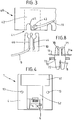
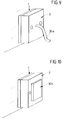
- Figures 5 and 6 schematically respectively represent a male connector of the "modular jack" type and a female connector of the same type.
- the male connector 60 has an elastic locking tab 62, adapted to snap into a housing 63 of the female connector 61 when the male connector is inserted in the female connector.
- the connector 6 is connected to four pairs of conductors 8, of which only two conductors 8 are shown in FIG. 2, for the sake of clarity.
- the four pairs of conductors 8 can come directly from a cable 9 of the pre-wired network; or, more advantageously, the eight conductors 8 can be connected respectively to eight double self-stripping contacts 10, such as for example the self-stripping contacts described in French patent application No. 90.8502 filed on July 4, 1990, and on the eight self-stripping contacts 10 in turn connect eight conductors 11 of the cable 9. Only two conductors 11 are shown in FIG. 2, for the sake of clarity.
- the double self-stripping contacts 10 are fixed to the base 1, for example by force fitting into housings 12 of the base 1, of shape substantially complementary to the shape of the self-stripping contacts 10.
- the advantage of using double self-stripping contacts 10 rather than directly connecting the conductors 11 of the cable 9 to the connector 6 lies in the fact that, in this way, the order of connection of the wires can be changed on request (distribution function) .
- the conductors 11 of the cable 9 are put in place using a tool cap 40, shown diagrammatically in FIG. 3 and described in detail in document EP-A- 0 100 802.
- the tool cap 40 is a molded plastic part which is suitable for covering the self-stripping contacts 10.
- the tool cap 40 has recesses 41 of shape adapted to receive the self-stripping contacts 10.
- the recesses 41 are laterally limited by two side walls 42 of the tool cap 40.
- the side walls 42 have two aligned holes 43, which allow the passage of a conductor 11 of the cable 9 and the insertion of said conductor 11 in a self-stripping slot 44 of a self-stripping contact 10 when said tool cap 40 comes to cap said self-stripping contact 10.
- the side walls 42 also have two aligned notches 4 5 which overlap a conductor 8 coming from the female intermediate connector 6, already inserted in the second self-stripping slot 46 of said self-stripping contact 10.
- the eight conductors 11 of the cable 9 can be inserted simultaneously and quickly on the eight contacts self-stripping 10, further eliminating the risk of accidentally putting a conductor 11 in a slot 46 already containing a conductor 8, which is a source of poor contact.
- the tool cap 40 remains in place after insertion of the conductors, and participates in maintaining the conductors in the self-stripping contacts 10.
- the base 1 further comprises two bores 13 which open on its front face 4.
- a socket 14 In each bore 13 is inserted in force a socket 14 internally threaded, the usefulness of which will be seen later.
- a simple self-stripping contact 15 In one of the sockets 14 is inserted by force a simple self-stripping contact 15, which receives a screen drain conductor 16 of the cable 9, connected to the ground (see FIG. 2).
- the front face 4 of the base 1 may include a transparent label holder 51.
- a concealment flap 5 can slide on the front face 4 between a low position where it obscures the female intermediate connector 6, and a high position where it allows the insertion of a complementary male connector into said female intermediate connector 6.
- the female intermediate connector 6 is protected from possible environmental attacks, such as dust, shocks, etc.
- the adapter box 2 consists of two parts 20 and 21 assembled by any known means, for example by snap-fastening, ultrasonic welding or gluing.
- One of the two parts 20 of the adapter box 2 has a rear face 22, in the form exterior identical to that of the front face 4 of the base 1, which is placed opposite the front face 4 of the base 1 when the adapter box 2 is assembled to the base 1, while the other part 21 has a front face 28.
- the rear face 22 has an opening which allows passage to an intermediate connector corresponding to connector 6, advantageously of the "modular jack" type 23, which projects outside the adapter box 2.
- the intermediate connector 23 is fixed to the adapter box 2 by snap-on arms 24 and by abutment against the rear face 22 of said box 2.
- the connector 23 is a male connector of the "modular jack” type, but does not include an elastic locking tab 62, unlike the male connectors of the "modular jack” type which are usually commercially, in order to be able to slide freely in the female intermediate connector 6 of the base 1: the removal of said elastic snap device is an inexpensive modification, and does not strike the cost of the socket.
- the connector 23 is a male connector of the "modular jack” type, which has a locking tab 62, as shown in FIG. 7, but the adapter box 2 is adapted to retract said locking tongue 62.
- the connector 23 can slide freely in the connector 6. It is thus possible to use a male connector "modular jack" 23 unmodified.
- the part 20 of the adapter box 2 further comprises two bores 25, facing the sockets 14 of the base 1. Each bore is traversed by a threaded rod 26a with a screw 26.
- the screw 26 has a head 26b wider than the bore 25 and which is inside the adapter box 2.
- the adapter box 2 can be put in place on the base 1 by fitting the male intermediate connector 23 into the intermediate connector female 6, and by screwing the screws 26 into the sockets 14 of the base 1 to fix the adapter box 2 to the base 1.
- the front face 28 of the adapter box 2 is provided with two holes 27 which allow '' access the heads 26b of the screws 26 using a screwdriver.
- One of the screws 26 has a terminal 26c which is clamped between the said screw 26 and the part 20 of the adapter box 2 when the screw 26 is screwed fully onto its socket 14.
- the front face 28 of the adapter box 2 further comprises an opening 29 which allows passage to an external connector 30, on which a connector can be inserted complementary to a device to be connected to the prewired network:
- the external connector 30 can be of any type, for example SUBD 9 points, SUBD 15 points, SUBD 25 points, DIN 5 points, coaxial cable connector, etc. It can be a purely electrical connector, or electro-optical if it serves as an interface with an optical cable.
- the external connector 30 is fixed to the adapter box 2 specifically for each type of connector.
- the external connector 30 has an enlarged base 31 which is inside the adapter box 2 and which cannot pass through the opening 29 of the front face 28: the enlarged base 31 is held in abutment against the front face 28 of the adapter box 2 by two screws 32.
- a metal end piece 33 surrounding the external connector 30 can be interposed between the screws 32 and the front face 28.
- the end piece 33 can be internally threaded and screwed onto the external connector 30.
- the shape of the opening 29 of the adapter box 2 as well as the thickness H of the part 21 of said adapter box 2 depend on the external connector 30 used.
- the part 20 of said adapter box 2 is independent of the external connector 30: thus, the part 20 can be produced in large series, at low cost.
- the electrical connection of the external connector 30 can be done in various ways.
- a conductor 34 can be connected both to a ground contact of the external connector 30 and to the terminal 26c, which is in electrical contact with the earth by means of the screw 26 on which the terminal is assembled, the corresponding socket 14, the simple self-stripping contact 15 and the screen drain conductor 16 of the cable 9.
- This arrangement is advantageous because it avoids the employment of male and female intermediate connectors 23 and 6 which have a ninth contact for the ground: such intermediate connectors are in fact more expensive than conventional “jack” type connectors with eight contacts.
- conductors 35 exit from the male intermediate connector 23, only four of the conductors 35 being shown in FIG. 2, for the sake of clarity.
- These conductors 35 can be connected directly to the external connector 30. More advantageously, they can be connected to double self-stripping contacts 36 fixed to the part 20 of the adapter box 2, and other conductors 37 leave from the self-stripping contacts 36 to the external connector 30.
- This allows on the one hand to use different color codes for the conductors 37 connected to the external connector 30 and for the conductors 35 connected to the male intermediate connector 23.
- this arrangement makes it possible to have parts 20 of the adapter box 2 identically prewired for several different external connectors, which allows the prewiring of part 20 in large series and therefore reduces the manufacturing cost. When assembling the adapter box 2, it therefore only remains to connect the conductors 37 connected to the external connector 30 to the double self-stripping contacts 36, which is quick and easy.
- the conductors 35 which exit from the male intermediate connector 23 can be connected to a printed circuit, placed inside the adapter box 2, connected to the conductors 37 which exit from the external connector 30.
- This arrangement makes it possible to interpose between the connectors 23 and 30 of the active elements such as "BALUN", ie transformers which make it possible to send a signal on a coaxial cable.
- the socket according to the invention can certainly be used to connect a device using a male connector of the "modular jack” type.
- the adapter box 2 can simply be removed, and the male connector "modular jack” of the device can be plugged directly onto the female intermediate connector 6 of the base 1.
- the connecting cable 30a of the device will be connected directly to the male intermediate connector 23 of an adapter box 2 which then no longer has an external connector 30, said connecting cable being mechanically linked to the adapter box 2.
- the external connector 30 could be replaced by a device 30b such as a temperature sensor, an intrusion detector (radar, infrared, ultrasonic sensor, etc.) for alarm system, or another sensor.
- a device 30b such as a temperature sensor, an intrusion detector (radar, infrared, ultrasonic sensor, etc.) for alarm system, or another sensor.
- the intrusion detector can be connected in series with at least one screw 26 and the socket 14 in which it is aimed, so that the contact is cut when the screw 26 is unscrewed from its socket 14.
- the housing 2 may not include screws 26, and the fixing of the housing 2 on the base can be done by snap-fastening.
- the self-stripping contacts 10 of the base 1 are triple, that is to say that they allow three conductive wires to be accommodated.
- the contacts 10 can comprise two slots 70, 71 which can be directed towards the rear of the base 1, and a slot 72 which can be directed towards the front face 4 of the base 1.
- the contact 10 can be fixed to the base 1 by any means, for example by snap-fitting or force fitting into a wall 73 which can be formed with the base 1 or attached to the base 1.
- Such triple contacts 10 are particularly advantageous in that they make it possible to make tap-to-tap derivations.
- the front slot 72 of the contact 10 which is the least accessible since it is located opposite the front face 4 of the base 1, can accommodate a conductor 8 connected to the intermediate connector 6 of the base, while one of the rear slots 70 accommodates a conductor 11 of the cable 9.
- a bypass socket (said derivative socket) to the socket to which the contact 10 belongs (said main socket)
- conductors 11a a in the slots 71 of each contact 10 possibly in the slots 71 of only part of the contacts 10) of the main socket, and of connecting the same conductors 11a in the rear slots 70 of corresponding contacts 10 in the branch socket. From the branch outlet, it is possible to make another branch to a third outlet, etc.
Landscapes
- Engineering & Computer Science (AREA)
- Architecture (AREA)
- Civil Engineering (AREA)
- Structural Engineering (AREA)
- Details Of Connecting Devices For Male And Female Coupling (AREA)
- Connector Housings Or Holding Contact Members (AREA)
- Coupling Device And Connection With Printed Circuit (AREA)
Claims (16)
- Schwachstromverbinder für die Vorverdrahtung eines Gebäudes, dadurch gekennzeichnet, daß er folgendes umfaßt:- Einen fest angebrachten Sockel (1), der einen Vorderteil (4) umfaßt, welcher mit einem ersten Zwischenverbinder (6) versehen ist, der mit einem Kabel (9) eines vorverdrahteten Netzes verbunden ist, wobei das Kabel mehrere Leiter (11) aufweist, und- ein lösbares, externes Adaptergehäuse (2), das einen hinteren Teil (20) aufweist, der am Vorderteil (4) des Sockels befestigt werden kann, wobei der hintere Teil (20) mit einem zweiten Zwischenverbinder (23) versehen ist, der zum ersten Zwischenverbinder (6) komplementär und geeignet ist, sich mit dem ersten Zwischenverbinder (6) zu verbinden, wenn das Adaptergehäuse (2) am Sockel befestigt wird, wobei das Adaptergehäuse (2) im übrigen eine elektrische Vorrichtung (30) umfaßt, die mit dem zweiten Zwischenverbinder (23) verbunden ist, um mit dem vorverdrahteten Netz in Verbindung zu treten.
- Verbinder nach Anspruch 1, dadurch gekennzeichnet, daß weiterhin der Sockel (1) die Isolation selbsttätig durchdringende Doppelkontakte (10) und Leiter (8) umfaßt, die mit dem ersten Zwischenverbinder (6) verbunden sind, wobei jeder die Isolation selbsttätig durchdringende Kontakt (10) so ausgebildet ist, daß er einen Leiter (8), der mit dem ersten Zwischenverbinder (6) verbunden ist, und einen Leiter (11) des Kabels (9) aufnehmen kann.
- Verbinder nach Anspruch 1, dadurch gekennzeichnet, daß weiterhin der Sockel die Isolation selbsttätig durchdringende Dreifachkontakte und Leiter (8) umfaßt, die mit dem ersten Zwischenverbinder (6) verbunden sind, wobei jeder die Isolation selbsttätig durchdringende Kontakt (10) so ausgebildet ist, daß er einen Leiter (8), der mit dem ersten Zwischenverbinder (6) verbunden ist, und einen Leiter (11) des Kabels (9) aufnehmen kann, und wobei weiterhin jeder die Isolation selbsttätig durchdringende Kontakt (10) so ausgebildet ist, daß er einen Leiter (11a) in Parallelverbindung zu einem anderen Verbinder aufnehmen kann.
- Verbinder nach Anspruch 2 oder 3, dadurch gekennzeichnet, daß weiterhin die Leiter (11) des Kabels (9) an einem Kappen-Werkzeug (40) befestigt sind, das ihr Einsetzen in den Sockel (1) erleichtert.
- Verbinder nach einem der vorhergehenden Ansprüche, dadurch gekennzeichnet, daß weiterhin das Adaptergehäuse (2) ein Vorderteil (21) umfaßt, das vom hinteren Teil des Adaptergehäuses (2) verschieden und an diesem hinteren Teil (20) befestigt ist, und daß der hintere Teil (20) von der elektrischen Vorrichtung unabhängig ist, die mit dem zweiten Zwischenverbinder verbunden ist.
- Verbinder nach einem der vorhergehenden Ansprüche, dadurch gekennzeichnet, daß weiterhin das Adaptergehäuse (2) Leiter (35), die mit dem zweiten Zwischenverbinder verbunden sind, Leiter (37), die mit der elektrischen Vorrichtung (30) verbunden sind, und die Isolation selbsttätig durchdringende Doppelkontakte (36) umfaßt, wobei jeder die Isolation selbsttätig durchdringende Doppelkontakt geeignet ist, einerseits einen Leiter (35), der mit dem zweiten Zwischenverbinder (23) verbunden ist, und andererseits einen Leiter (37) aufzunehmen, der mit der elektrischen Vorrichtung (30) verbunden ist.
- Verbinder nach einem der vorhergehenden Ansprüche, dadurch gekennzeichnet, daß das Kabel (9) weiterhin eine Abschirmung (16) umfaßt, und daß der Verbinder leitende Teile (26, 14, 15) aufweist, die die Abschirmung (16) des Kabels (9) mit der elektrischen Vorrichtung (30) verbinden.
- Verbinder nach Anspruch 7, dadurch gekennzeichnet, daß weiterhin der Sockel (1) und das Adaptergehäuse (2) durch Verschrauben zusammengefügt sind, und daß die leitenden Teile von einer Schraube (26), einer entsprechenden Buchse (14) und einem die Isolation selbsttätig durchdringenden Kontakt (15) gebildet werden, der mit der Buchse (14) in Kontakt steht, wobei die Abschirmung (16) des Kabels (9) mit dem die Isolation selbsttätig durchdringenden Kontakt (15) verbunden ist und ein Leiter (34) die Schraube (26) mit der elektrischen Vorrichtung (30) verbindet.
- Verbinder nach einem der vorhergehenden Ansprüche, dadurch gekennzeichnet, daß weiterhin der Sockel (1) eine Abdeckklappe (52) für den ersten Zwischenverbinder (6) umfaßt.
- Verbinder nach einem der vorhergehenden Ansprüche, dadurch gekennzeichnet, daß weiterhin der erste Zwischenverbinder (6) und der zweite Zwischenverbinder (23) Standardverbinder sind.
- Verbinder nach Anspruch 10, dadurch gekennzeichnet, daß weiterhin der erste Zwischenverbinder (6) und der zweite Zwischenverbinder (23) "Modular-Jack"-Verbinder sind.
- Verbinder nach Anspruch 11, dadurch gekennzeichnet, daß weiterhin einer der beiden Zwischenverbinder (6, 23) ein eindringender "Modular-Jack"-Verbinder ist, der eine elastische Verriegelungslasche (62) umfaßt, und daß der Verbinder Mittel (22a) umfaßt, die dazu dienen, die elastische Verriegelungslasche (62) einzuziehen und in der Weise unwirksam zu machen, daß der erste und der zweite Zwischenverbinder (6, 23) durch eine einfache Relativverschiebung voneinander entkoppelt werden können.
- Verbinder nach Anspruch 11, dadurch gekennzeichnet, daß weiterhin einer der Zwischenverbinder (6, 23) ein eindringender "Modular-Jack"-Verbinder ist, der normalerweise eine elastische Verriegelungslasche (62) umfaßt und der so abgewandelt ist, daß er diese elastische Verriegelungszunge nicht aufweist, so daß der erste und zweite Zwischenverbinder (6, 23) durch eine einfache Relativverschiebung voneinander entkoppelt werden können.
- Verbinder nach einem der vorhergehenden Ansprüche, dadurch gekennzeichnet, daß weiterhin die elektrische Vorrichtung ein elektrischer Verbinder (30) ist, der von außen her zugänglich ist.
- Verbinder nach einem der Ansprüche 1 bis 13, dadurch gekennzeichnet, daß die elektrische Vorrichtung ein Kabel (30a) ist, das mit einem externen Apparat verbunden ist.
- Verbinder nach einem der Ansprüche 1 bis 13, dadurch gekennzeichnet, daß weiterhin die elektrische Vorrichtung ein Sensor (30b) ist.
Applications Claiming Priority (2)
| Application Number | Priority Date | Filing Date | Title |
|---|---|---|---|
| FR9013564 | 1990-10-31 | ||
| FR9013564A FR2668658B1 (fr) | 1990-10-31 | 1990-10-31 | Prise courants faibles pour precablage de batiment. |
Publications (2)
| Publication Number | Publication Date |
|---|---|
| EP0484243A1 EP0484243A1 (de) | 1992-05-06 |
| EP0484243B1 true EP0484243B1 (de) | 1995-07-26 |
Family
ID=9401765
Family Applications (1)
| Application Number | Title | Priority Date | Filing Date |
|---|---|---|---|
| EP91402918A Expired - Lifetime EP0484243B1 (de) | 1990-10-31 | 1991-10-30 | Schwachstromverbinder für die Vorverdrahtung eines Gebäudes |
Country Status (6)
| Country | Link |
|---|---|
| US (1) | US5176534A (de) |
| EP (1) | EP0484243B1 (de) |
| JP (1) | JPH04264377A (de) |
| DE (1) | DE69111568T2 (de) |
| ES (1) | ES2077826T3 (de) |
| FR (1) | FR2668658B1 (de) |
Families Citing this family (13)
| Publication number | Priority date | Publication date | Assignee | Title |
|---|---|---|---|---|
| FR2687509A1 (fr) * | 1992-02-17 | 1993-08-20 | Nozick Jacques | Boitier support de prises electriques normalisees et element de precablage incluant un tel boitier. |
| FR2694456B1 (fr) * | 1992-07-31 | 1994-09-09 | Pouyet Int | Prise femelle de type "modular jack" et à connectique intégrée. |
| US5328390A (en) * | 1992-09-01 | 1994-07-12 | Hubbell Incorporated | Modular telecommunication jack adapter |
| FR2698493B1 (fr) * | 1992-11-23 | 1995-03-03 | Arnould App Electr | Connecteur électrique. |
| US5449299A (en) * | 1994-01-24 | 1995-09-12 | Raychem Corporation | Telecommunications terminal |
| FR2718893B1 (fr) * | 1994-04-15 | 1996-07-12 | Jacques Nozick | Prise adaptable pour précâblage banalisé, pour système de communication. |
| US5649829A (en) * | 1995-07-21 | 1997-07-22 | Miller; Mitchell Eugene | Low profile distribution adapter for use with twisted pair cables |
| US5759061A (en) * | 1996-08-15 | 1998-06-02 | Raychem Corporation | IDC having wire slippage control |
| DE19709972A1 (de) * | 1997-03-11 | 1998-09-17 | Siemens Ag | Verteilnetz mit mindestens zwei auf getrennten Leitungen geführten Informationskanälen |
| US6475009B2 (en) * | 2000-06-02 | 2002-11-05 | The Siemon Company | Industrial telecommunications connector |
| JP4717295B2 (ja) * | 2000-10-04 | 2011-07-06 | 株式会社半導体エネルギー研究所 | ドライエッチング装置及びエッチング方法 |
| WO2004079376A2 (en) * | 2003-02-28 | 2004-09-16 | Alden Products Company | Ruggedized ethernet connector assembly |
| CN101997222B (zh) * | 2009-08-13 | 2014-01-22 | 鸿富锦精密工业(深圳)有限公司 | 水晶头 |
Family Cites Families (5)
| Publication number | Priority date | Publication date | Assignee | Title |
|---|---|---|---|---|
| EP0100802A1 (de) * | 1982-08-06 | 1984-02-22 | C.T.M. | Kontaktschutzvorrichtung |
| US4725249A (en) * | 1986-09-22 | 1988-02-16 | American Telephone & Telegraph Company | Connector assembly |
| US4964812A (en) * | 1989-11-21 | 1990-10-23 | The Siemon Company | Wire termination block |
| US5007860A (en) * | 1990-01-19 | 1991-04-16 | Leviton Manufacturing Co., Inc. | Modular higher density communications coupling system |
| US5055067A (en) * | 1990-02-23 | 1991-10-08 | Communications Systems, Inc. | Modular patch panel for telecommunication system |
-
1990
- 1990-10-31 FR FR9013564A patent/FR2668658B1/fr not_active Expired - Fee Related
-
1991
- 1991-10-30 ES ES91402918T patent/ES2077826T3/es not_active Expired - Lifetime
- 1991-10-30 DE DE69111568T patent/DE69111568T2/de not_active Expired - Fee Related
- 1991-10-30 US US07/785,063 patent/US5176534A/en not_active Expired - Lifetime
- 1991-10-30 EP EP91402918A patent/EP0484243B1/de not_active Expired - Lifetime
- 1991-10-31 JP JP3313872A patent/JPH04264377A/ja not_active Withdrawn
Also Published As
| Publication number | Publication date |
|---|---|
| FR2668658A1 (fr) | 1992-04-30 |
| DE69111568T2 (de) | 1996-03-14 |
| JPH04264377A (ja) | 1992-09-21 |
| US5176534A (en) | 1993-01-05 |
| FR2668658B1 (fr) | 1994-01-28 |
| EP0484243A1 (de) | 1992-05-06 |
| DE69111568D1 (de) | 1995-08-31 |
| ES2077826T3 (es) | 1995-12-01 |
Similar Documents
| Publication | Publication Date | Title |
|---|---|---|
| EP0484243B1 (de) | Schwachstromverbinder für die Vorverdrahtung eines Gebäudes | |
| EP2239605B1 (de) | Verbindungssystem für opto-elektronische Module und Glasfasern | |
| EP3267232B1 (de) | Verbindungssystem einer vielzahl von steckerstiften an eine monoblockanordnung, bestehend aus einem gehäusepaneel eines elektronischen geräts und einer vielzahl von buchsen | |
| FR3053846A1 (fr) | Fiche de connexion a une embase de panneau de boitier d'equipement electronique, munie de moyens d'auto-alignement | |
| FR2694456A1 (fr) | Prise femelle de type "modular jack" et à connectique intégrée. | |
| FR2807223A1 (fr) | Connecteur | |
| EP1037332A1 (de) | Schwachstromstecker mit einem Adapter und Adapter für einen solchen Stecker | |
| FR3014603A1 (fr) | Connecteur electrique femelle, connecteur electrique male correspondant et ensemble de connexion comportant des connecteurs male et femelle | |
| EP1271713B1 (de) | Schwachstrom-Modular Jackverbinder | |
| EP0805605A1 (de) | Abzweigverbinder für Übertragungsnetze, insbesondere für die Telephonie und Datenverarbeitung | |
| EP0890207A1 (de) | Verbindungsvorrichtung insbesondere für faseroptisches netz | |
| EP0608184A1 (de) | Modularer Differenzstromschutzschalter | |
| FR2702097A1 (fr) | Assemblage de connecteurs électriques, borne électrique d'une seule pièce et connecteur électrique. | |
| EP2643902B1 (de) | Rj45-adapter mit mehrfachzugriff | |
| EP3531142B1 (de) | Vorrichtung zum messen mindestens einer elektrischen grösse eines stroms, der in mindestens einem elektrischen gerät fliesst | |
| FR2813998A1 (fr) | Dispositif comprenant un boitier et un connecteur pour liaison a un cable coaxial et procede de fabrication d'un tel dispositif | |
| FR3040244A1 (fr) | Prise electrique comprenant un circuit imprime | |
| WO1998047031A1 (fr) | Prise opto-electrique et ensemble de connexion opto-electrique pour le precablage de batiment | |
| FR2691846A1 (fr) | Prise de courant électrique à contact auto-dénudant. | |
| EP2958195A1 (de) | Modul-vorrichtung für kommunikationsbox | |
| FR2602375A1 (fr) | Dispositif de raccordement electrique | |
| EP3985817B1 (de) | Verschluss für ein gehäuse zur aufnahme von mindestens einem kabelende und entsprechendes gehäuse | |
| FR2994346A1 (fr) | Capot d'hebergement de modules electriques a assemblage d'organe de connexion facilite | |
| FR2802351A1 (fr) | Dispositif de connexion pour un appareil de communication | |
| FR2815775A1 (fr) | Prise de courants faibles du type "modular jack" comprenant un peigne amovible de positionnement des fils electriques au-dessus des contacts metalliques autodenudants |
Legal Events
| Date | Code | Title | Description |
|---|---|---|---|
| PUAI | Public reference made under article 153(3) epc to a published international application that has entered the european phase |
Free format text: ORIGINAL CODE: 0009012 |
|
| AK | Designated contracting states |
Kind code of ref document: A1 Designated state(s): BE DE ES FR GB IT |
|
| 17P | Request for examination filed |
Effective date: 19920721 |
|
| 17Q | First examination report despatched |
Effective date: 19941216 |
|
| GRAA | (expected) grant |
Free format text: ORIGINAL CODE: 0009210 |
|
| AK | Designated contracting states |
Kind code of ref document: B1 Designated state(s): BE DE ES FR GB IT |
|
| REF | Corresponds to: |
Ref document number: 69111568 Country of ref document: DE Date of ref document: 19950831 |
|
| GBT | Gb: translation of ep patent filed (gb section 77(6)(a)/1977) |
Effective date: 19950812 |
|
| ITF | It: translation for a ep patent filed | ||
| REG | Reference to a national code |
Ref country code: ES Ref legal event code: FG2A Ref document number: 2077826 Country of ref document: ES Kind code of ref document: T3 |
|
| REG | Reference to a national code |
Ref country code: FR Ref legal event code: TP |
|
| PLBE | No opposition filed within time limit |
Free format text: ORIGINAL CODE: 0009261 |
|
| STAA | Information on the status of an ep patent application or granted ep patent |
Free format text: STATUS: NO OPPOSITION FILED WITHIN TIME LIMIT |
|
| 26N | No opposition filed | ||
| REG | Reference to a national code |
Ref country code: GB Ref legal event code: IF02 |
|
| PGFP | Annual fee paid to national office [announced via postgrant information from national office to epo] |
Ref country code: DE Payment date: 20051014 Year of fee payment: 15 |
|
| PGFP | Annual fee paid to national office [announced via postgrant information from national office to epo] |
Ref country code: ES Payment date: 20051017 Year of fee payment: 15 Ref country code: GB Payment date: 20051017 Year of fee payment: 15 |
|
| PGFP | Annual fee paid to national office [announced via postgrant information from national office to epo] |
Ref country code: FR Payment date: 20051027 Year of fee payment: 15 |
|
| PGFP | Annual fee paid to national office [announced via postgrant information from national office to epo] |
Ref country code: BE Payment date: 20051108 Year of fee payment: 15 |
|
| PGFP | Annual fee paid to national office [announced via postgrant information from national office to epo] |
Ref country code: IT Payment date: 20061031 Year of fee payment: 16 |
|
| PG25 | Lapsed in a contracting state [announced via postgrant information from national office to epo] |
Ref country code: DE Free format text: LAPSE BECAUSE OF NON-PAYMENT OF DUE FEES Effective date: 20070501 |
|
| GBPC | Gb: european patent ceased through non-payment of renewal fee |
Effective date: 20061030 |
|
| REG | Reference to a national code |
Ref country code: FR Ref legal event code: ST Effective date: 20070629 |
|
| PG25 | Lapsed in a contracting state [announced via postgrant information from national office to epo] |
Ref country code: GB Free format text: LAPSE BECAUSE OF NON-PAYMENT OF DUE FEES Effective date: 20061030 |
|
| BERE | Be: lapsed |
Owner name: *NOZICK JACQUES E. Effective date: 20061031 |
|
| REG | Reference to a national code |
Ref country code: ES Ref legal event code: FD2A Effective date: 20061031 |
|
| PG25 | Lapsed in a contracting state [announced via postgrant information from national office to epo] |
Ref country code: FR Free format text: LAPSE BECAUSE OF NON-PAYMENT OF DUE FEES Effective date: 20061031 Ref country code: ES Free format text: LAPSE BECAUSE OF NON-PAYMENT OF DUE FEES Effective date: 20061031 |
|
| PG25 | Lapsed in a contracting state [announced via postgrant information from national office to epo] |
Ref country code: BE Free format text: LAPSE BECAUSE OF FAILURE TO SUBMIT A TRANSLATION OF THE DESCRIPTION OR TO PAY THE FEE WITHIN THE PRESCRIBED TIME-LIMIT Effective date: 20061031 Ref country code: IT Free format text: LAPSE BECAUSE OF NON-PAYMENT OF DUE FEES Effective date: 20071030 |