EP1014414A1 - Elektrisches Gerät wie ein Leistungsschalter oder ein moduläre Schalter - Google Patents
Elektrisches Gerät wie ein Leistungsschalter oder ein moduläre Schalter Download PDFInfo
- Publication number
- EP1014414A1 EP1014414A1 EP99410171A EP99410171A EP1014414A1 EP 1014414 A1 EP1014414 A1 EP 1014414A1 EP 99410171 A EP99410171 A EP 99410171A EP 99410171 A EP99410171 A EP 99410171A EP 1014414 A1 EP1014414 A1 EP 1014414A1
- Authority
- EP
- European Patent Office
- Prior art keywords
- plane
- terminals
- face
- intended
- connection
- Prior art date
- Legal status (The legal status is an assumption and is not a legal conclusion. Google has not performed a legal analysis and makes no representation as to the accuracy of the status listed.)
- Granted
Links
Images


Classifications
-
- H—ELECTRICITY
- H02—GENERATION; CONVERSION OR DISTRIBUTION OF ELECTRIC POWER
- H02B—BOARDS, SUBSTATIONS OR SWITCHING ARRANGEMENTS FOR THE SUPPLY OR DISTRIBUTION OF ELECTRIC POWER
- H02B1/00—Frameworks, boards, panels, desks, casings; Details of substations or switching arrangements
- H02B1/20—Bus-bar or other wiring layouts, e.g. in cubicles, in switchyards
- H02B1/205—Bus-bar or other wiring layouts, e.g. in cubicles, in switchyards for connecting electrical apparatus mounted side by side on a rail
-
- H—ELECTRICITY
- H01—ELECTRIC ELEMENTS
- H01H—ELECTRIC SWITCHES; RELAYS; SELECTORS; EMERGENCY PROTECTIVE DEVICES
- H01H71/00—Details of the protective switches or relays covered by groups H01H73/00 - H01H83/00
- H01H71/08—Terminals; Connections
- H01H71/082—Connections between juxtaposed circuit breakers
-
- H—ELECTRICITY
- H01—ELECTRIC ELEMENTS
- H01H—ELECTRIC SWITCHES; RELAYS; SELECTORS; EMERGENCY PROTECTIVE DEVICES
- H01H11/00—Apparatus or processes specially adapted for the manufacture of electric switches
- H01H11/0006—Apparatus or processes specially adapted for the manufacture of electric switches for converting electric switches
- H01H11/0031—Apparatus or processes specially adapted for the manufacture of electric switches for converting electric switches for allowing different types or orientation of connections to contacts
- H01H2011/0037—Apparatus or processes specially adapted for the manufacture of electric switches for converting electric switches for allowing different types or orientation of connections to contacts with removable or replaceable terminal blocks
Definitions
- the invention relates to an electrical device such as a circuit breaker intended to be fixed to a support such as a rail and housed in a housing of substantially parallelepiped shape, said housing comprising a rear face for fixing to the support and a front face, said faces being substantially parallel to each other, two main faces substantially parallel to each other them and perpendicular to the front and rear faces, by which said housing can be attached to the boxes of other devices of the same type, all the devices being mounted aligned with the support, and at least one connection face, said face of connection comprising at least one input terminal and at least one output terminal, the at least one input terminal being located in a plane, called the first plane, perpendicular to the face connection and parallel to the alignment direction of the devices.
- the present invention solves this problem and proposes an electrical device such as a modular switch or circuit breaker, for which the supply and downstream connection devices can be done from above, and which can receive larger sizes without increasing its size on the rail.
- the present invention relates to an apparatus of the kind previously mentioned, this apparatus being characterized in that the or each output terminal is located in a so-called second plane, substantially parallel to the first but offset from the latter depending on the depth of the device housing, the input terminal (s) being located respectively opposite the corresponding output terminal (s) parallel to the plane of the connection face and perpendicular to the direction of alignment of the appliances.
- At least one of the input terminals or output terminals includes a racking clamp.
- all the terminals are fitted with racking-in pliers, the input terminals cooperating with a connector intended to receive a cable, while the output terminals are intended to receive the teeth with a comb.
- a differential switch I of the type generally used to protect one or more electrical circuits against earth fault currents.
- This switch I is intended to be mounted on a support in this case a mounting rail 1, and to be electrically connected in series to one or more electrical protection elements (not shown) also mounted on the rail 1, such as cut -fuse circuits or circuit breakers.
- This differential switch I, as well as the other devices are of the modular type, each module (a, b, c, d) containing a phase or neutral cut-off unit and housing an input terminal and an output terminal .
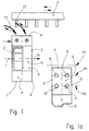
- These devices are each housed in a housing B of substantially parallelepiped shape, said housing B comprising two main parallel faces 2, 3 by which the housing B of two devices can be joined, a rear face 4 for fixing to the mounting rail 1, a front face 5, said front 5 and rear 4 faces being perpendicular to the main faces 2,3, and two connecting faces 6,7 parallel to each other and perpendicular to the main faces 2,3 and to the aforementioned front 5 and rear 4 faces.
- the device is of the unipolar and neutral type and consists of two modules a, b respectively housing a neutral cutoff unit and a phase cutout unit. Only one 6 of the connection faces 6,7 of this device has terminals for connection 8 to 11. According to the invention, and as this is particularly visible on the FIG. 1a, this connection face 6 comprises two input terminals 8.9 respectively neutral and phase, located in a first plane P1 perpendicular to the face of connection 6 and parallel to rail 1 and two output terminals 10,11 respectively of neutral and phase and located in a second plane P2 parallel to the first P1, but offset relative to this first plane P1 along the depth of the housing B.
- This depth is defined perpendicular to the plane P3 of the device on the rail 1 (or plane of the support 1) and parallel to the connection face 6.
- the above-mentioned first plane P1 is located between the support 1 and the aforementioned second plane P2.
- the two input terminals 8.9 are intended to receive two power cables 12,13 respectively while the two terminals of outlet 10.11 are intended to receive two 14.15 consecutive teeth of a comb classic P connection of the unipolar and neutral type.
- the caliber of this device is 63A.
- the device is of the three-pole and neutral type and comprises, in the same way as for the device in the previous figure, on its connection face 6, a set of four input terminals (not shown) aligned in a first plane perpendicular to the connection face and parallel to the direction D of alignment of the devices, that is to say to the rail. And it also includes a set of four output terminals 14,17 aligned in a second plane (not shown) parallel to the first plane P1, said second plane being offset from the first P1 according to the depth of the housing.
- the device is also of the three-pole and neutral type and comprises four modules a, b, c, d with a width of 18mm.
- first plane P1 On its connection face 6 are placed in a first plane P1 four input terminals 18 to 21 each intended to receive a power cable and in a second plane P2, offset in depth with respect to the first P1, for each module, a terminal 22 to 25 and a recess 26 to 29, said recess being intended to receive an unused tooth of a comb Q whose pitch is 9 mm, said comb Q distributing successively the different phases with the interposition of a tooth of neutral n between two successive phase teeth.
- connection face 6 of the device I is constituted of two portions of surfaces 6a, 6b offset according to the height of the device. This height is defined parallel to the fixing plane P3 and to the front 5 and rear 4 faces, and perpendicular to the connection faces 6,7.
- the connection surface portion 6a located on the upper level houses the input terminals 30 of the device, while the surface portion 6b located at the lower level houses the output terminals 31 intended for cooperate with a comb P.
- the terminals are of the type screw cage.
- One of the advantages of this embodiment is that the offset of the two surface portions 6a, 6b generates the presence of a wall portion 6c forming a screen between the input terminals 30 and the output terminals 31 and intended to prevent the operator from inadvertently connect an input terminal 30 and an output terminal 31 by means of said comb P.
- the input 30 and output 31 terminals are located on the same horizontal plane P4, that is to say parallel to the connection face 6. It a separation wall 32 has therefore been provided between the two sets of terminals 30, 31 extending parallel to the alignment direction of the devices, i.e. parallel to the direction of the rail and to the front 5 and rear 4 faces and whose height is such that said wall dissuades the operator from electrically connecting an input terminal 30 to a terminal outlet 31 via a comb or the like.
- the terminals 31 and the input terminals 30 each house a racking clamp 33.
- the clamps plug-in 33 output terminals 31 are intended to receive the teeth respectively d of a comb P, while the clamps 33 housed in the input terminals 30 are intended for each receiving a contact pad 34 belonging to a power connector 35, said connector 35 being itself intended to receive a power cable 36.
- an electrical device for which the supply and connection to the devices located downstream are carried out on the same side and therefore advantageously from the top of the devices, said device being able to withstand large sizes in space on the rail (36mm) corresponding to that of the devices of the prior art.
- the invention is not limited to the embodiments described and illustrated which have been given only by way of example.
- all the input terminals are aligned in the same plane, as are the output terminals.
- the invention also applies to the case where the phase input terminals are aligned in one plane and the neutral input terminals are aligned in another plane parallel to the first. This also applies to the output terminals.
- the support could be made up of something other than a rail, say any support plan on which the devices can be individually fixed.
- the invention applies to any electrical device having on the same face of the input terminals and output terminals, and intended to supply other devices with which it is aligned on the same support.
Landscapes
- Engineering & Computer Science (AREA)
- Power Engineering (AREA)
- Breakers (AREA)
- Connections Arranged To Contact A Plurality Of Conductors (AREA)
- Switch Cases, Indication, And Locking (AREA)
- Driving Mechanisms And Operating Circuits Of Arc-Extinguishing High-Tension Switches (AREA)
- Keying Circuit Devices (AREA)
Applications Claiming Priority (2)
| Application Number | Priority Date | Filing Date | Title |
|---|---|---|---|
| FR9816579 | 1998-12-23 | ||
| FR9816579A FR2787917B1 (fr) | 1998-12-23 | 1998-12-23 | Appareil electrique tel un disjoncteur ou un interrupteur modulaire |
Publications (2)
| Publication Number | Publication Date |
|---|---|
| EP1014414A1 true EP1014414A1 (de) | 2000-06-28 |
| EP1014414B1 EP1014414B1 (de) | 2006-06-07 |
Family
ID=9534624
Family Applications (1)
| Application Number | Title | Priority Date | Filing Date |
|---|---|---|---|
| EP99410171A Expired - Lifetime EP1014414B1 (de) | 1998-12-23 | 1999-11-26 | Elektrisches Gerät wie ein Leistungsschalter oder ein moduläre Schalter |
Country Status (7)
| Country | Link |
|---|---|
| EP (1) | EP1014414B1 (de) |
| CN (1) | CN1260578A (de) |
| AT (1) | ATE329368T1 (de) |
| BR (1) | BR9905972A (de) |
| DE (1) | DE69931742T2 (de) |
| ES (1) | ES2263262T3 (de) |
| FR (1) | FR2787917B1 (de) |
Cited By (6)
| Publication number | Priority date | Publication date | Assignee | Title |
|---|---|---|---|---|
| EP1220257A1 (de) * | 2000-12-20 | 2002-07-03 | Schneider Electric Industries SA | Elektrische Anschlussvorrichtung für zwei elektrische Geräte wie ein elektrisches Schutzgerät und einen gesteuerten Schalter, und daran angepasstes elektrisches Gerät |
| FR2841376A1 (fr) * | 2002-06-25 | 2003-12-26 | Schneider Electric Ind Sa | Ensemble de protection et de commande electromagnetique |
| FR2841377A1 (fr) * | 2002-06-25 | 2003-12-26 | Schneider Electric Ind Sa | Ensemble de protection et de commande electromagnetique |
| EP1432001A1 (de) * | 2002-12-20 | 2004-06-23 | Hager Electro | Elektrisches Gerät, beispielsweise modulares elektrisches Gerät mit einem zweiteiligen Gehäuse |
| EP1447829A1 (de) * | 2003-02-14 | 2004-08-18 | Siemens Aktiengesellschaft | Installationsgerät und Installationsbaugruppe mit Installationsgerät |
| EP2131379A1 (de) * | 2008-06-05 | 2009-12-09 | Legrand France | Dreiphasen-Schutzschalter und entsprechender Dreiphasendifferentialschutzschalter |
Families Citing this family (3)
| Publication number | Priority date | Publication date | Assignee | Title |
|---|---|---|---|---|
| DE102004043468A1 (de) * | 2004-09-08 | 2006-03-30 | Siemens Ag | Schaltgerät mit steckbaren Anschlüssen |
| FR2977085B1 (fr) * | 2011-06-23 | 2013-10-18 | Schneider Electric Ind Sas | Dispositif de raccordement electrique d'au moins un conducteur a respectivement au moins une plage de contact d'un appareil electrique et appareil electrique le comportant. |
| CN102523709B (zh) * | 2011-11-23 | 2015-05-13 | 波普电气有限公司 | 外壳同一侧配有输入和输出端子的电子装置 |
Citations (5)
| Publication number | Priority date | Publication date | Assignee | Title |
|---|---|---|---|---|
| FR2125425A1 (de) * | 1971-02-13 | 1972-09-29 | Bbc Brown Boveri & Cie | |
| DE7813854U1 (de) * | 1978-05-08 | 1979-10-11 | Licentia Patent-Verwaltungs-Gmbh, 6000 Frankfurt | Mit einem mehrpoligen Leitungsschutzschalter kombinierter Fehlerstromschutzschalter |
| DE3023499A1 (de) * | 1980-06-24 | 1982-01-14 | Brown, Boveri & Cie Ag, 6800 Mannheim | Elektrisches installationsgeraet |
| EP0704874A1 (de) * | 1994-09-28 | 1996-04-03 | Schneider Electric Sa | Differentialschutzschalter zugeordnet zu einem oder mehreren Schaltungsschutzelementen wie Schmelzsicherungen oder Schutzschalter |
| FR2730855A1 (fr) * | 1995-02-21 | 1996-08-23 | Legrand Sa | Appareil electrique modulaire a evidement sur une face laterale |
-
1998
- 1998-12-23 FR FR9816579A patent/FR2787917B1/fr not_active Expired - Fee Related
-
1999
- 1999-11-26 AT AT99410171T patent/ATE329368T1/de not_active IP Right Cessation
- 1999-11-26 DE DE69931742T patent/DE69931742T2/de not_active Expired - Lifetime
- 1999-11-26 EP EP99410171A patent/EP1014414B1/de not_active Expired - Lifetime
- 1999-11-26 ES ES99410171T patent/ES2263262T3/es not_active Expired - Lifetime
- 1999-12-23 BR BR9905972-0A patent/BR9905972A/pt not_active IP Right Cessation
- 1999-12-23 CN CN99127819.4A patent/CN1260578A/zh active Pending
Patent Citations (5)
| Publication number | Priority date | Publication date | Assignee | Title |
|---|---|---|---|---|
| FR2125425A1 (de) * | 1971-02-13 | 1972-09-29 | Bbc Brown Boveri & Cie | |
| DE7813854U1 (de) * | 1978-05-08 | 1979-10-11 | Licentia Patent-Verwaltungs-Gmbh, 6000 Frankfurt | Mit einem mehrpoligen Leitungsschutzschalter kombinierter Fehlerstromschutzschalter |
| DE3023499A1 (de) * | 1980-06-24 | 1982-01-14 | Brown, Boveri & Cie Ag, 6800 Mannheim | Elektrisches installationsgeraet |
| EP0704874A1 (de) * | 1994-09-28 | 1996-04-03 | Schneider Electric Sa | Differentialschutzschalter zugeordnet zu einem oder mehreren Schaltungsschutzelementen wie Schmelzsicherungen oder Schutzschalter |
| FR2730855A1 (fr) * | 1995-02-21 | 1996-08-23 | Legrand Sa | Appareil electrique modulaire a evidement sur une face laterale |
Cited By (13)
| Publication number | Priority date | Publication date | Assignee | Title |
|---|---|---|---|---|
| EP1220257A1 (de) * | 2000-12-20 | 2002-07-03 | Schneider Electric Industries SA | Elektrische Anschlussvorrichtung für zwei elektrische Geräte wie ein elektrisches Schutzgerät und einen gesteuerten Schalter, und daran angepasstes elektrisches Gerät |
| US6888077B2 (en) | 2002-06-25 | 2005-05-03 | Schneider Electric Industries Sas | Electromagnetic protection and control assembly |
| FR2841377A1 (fr) * | 2002-06-25 | 2003-12-26 | Schneider Electric Ind Sa | Ensemble de protection et de commande electromagnetique |
| EP1376637A1 (de) * | 2002-06-25 | 2004-01-02 | Schneider Electric Industries SAS | Elektromagnetische Steuerungs- und Schutzvorrichtung |
| EP1376638A1 (de) * | 2002-06-25 | 2004-01-02 | Schneider Electric Industries SAS | Elektromagnetischer Schütz und Steuereinheit |
| US6840823B2 (en) | 2002-06-25 | 2005-01-11 | Schneider Electric Industries Sas | Electromagnetic protection and control assembly |
| FR2841376A1 (fr) * | 2002-06-25 | 2003-12-26 | Schneider Electric Ind Sa | Ensemble de protection et de commande electromagnetique |
| KR100964068B1 (ko) * | 2002-06-25 | 2010-06-16 | 슈나이더 일렉트릭 인더스트리스 에스에이에스 | 전자기 보호 및 제어 어셈블리 |
| EP1432001A1 (de) * | 2002-12-20 | 2004-06-23 | Hager Electro | Elektrisches Gerät, beispielsweise modulares elektrisches Gerät mit einem zweiteiligen Gehäuse |
| EP1447829A1 (de) * | 2003-02-14 | 2004-08-18 | Siemens Aktiengesellschaft | Installationsgerät und Installationsbaugruppe mit Installationsgerät |
| WO2004073006A1 (de) * | 2003-02-14 | 2004-08-26 | Siemens Aktiengesellschaft | Installationsgerät und installationsbaugruppe mit installationsgerät |
| EP2131379A1 (de) * | 2008-06-05 | 2009-12-09 | Legrand France | Dreiphasen-Schutzschalter und entsprechender Dreiphasendifferentialschutzschalter |
| FR2932311A1 (fr) * | 2008-06-05 | 2009-12-11 | Legrand France | Disjoncteur triphase et disjoncteur differentiel triphase associe. |
Also Published As
| Publication number | Publication date |
|---|---|
| CN1260578A (zh) | 2000-07-19 |
| ES2263262T3 (es) | 2006-12-01 |
| FR2787917A1 (fr) | 2000-06-30 |
| ATE329368T1 (de) | 2006-06-15 |
| FR2787917B1 (fr) | 2001-03-16 |
| DE69931742D1 (de) | 2006-07-20 |
| DE69931742T2 (de) | 2007-01-04 |
| BR9905972A (pt) | 2000-08-29 |
| EP1014414B1 (de) | 2006-06-07 |
Similar Documents
| Publication | Publication Date | Title |
|---|---|---|
| EP1376638B1 (de) | Elektromagnetischer Schutz und Steuereinheit | |
| EP1881574A2 (de) | Vorrichtung zur Aufteilung der Leistungsstromversorgung für eine Reihe von modularen Geräten in einer elektrischen Schalttafel | |
| EP1137035A1 (de) | Einrichtung zum elektrischen Anschliessen von mehreren modularen elektrischen Vorrichtungen | |
| FR2787238A1 (fr) | Appareil electrique modulaire tel un disjoncteur | |
| EP1014414B1 (de) | Elektrisches Gerät wie ein Leistungsschalter oder ein moduläre Schalter | |
| FR2765407A1 (fr) | Dispositif d'alimentation et d'assemblage d'une pluralite d'appareils electriques | |
| EP0237388B1 (de) | Speise- oder Überbrückungsgerät für nebeneinander stehende elektrische Einrichtungen | |
| EP3667845B1 (de) | Fertighalterung für einen elektrischen einschub, und elektrische vorrichtung, die eine solche halterung umfasst | |
| EP3641063B1 (de) | Vorrichtung zur stromversorgung und zum elektrischen anschluss eines schützes an einen satz modularer elektrischer einheiten, die nebeneinander auf einer montageschiene montiert sind und system mit einer solchen vorrichtung | |
| EP1058348B1 (de) | Elektrische Versorgungseinrichtung für elektrische Leistungsapparatemodule wie Schutzschalter, sowie ein die Vorrichtung enthaltendes Schaltgerät | |
| EP0114539B1 (de) | Verbindungsvorrichtung mit Sammelschienen | |
| EP0901143B1 (de) | Anordnung zum Zusammenbauen und Verbinden elektrischer Leistungsapparatemodule wie Schutzschalter | |
| EP1376637B1 (de) | Elektromagnetische Steuerungs- und Schutzvorrichtung | |
| EP0704874B1 (de) | Differentialschutzschalter zugeordnet zu einem oder mehreren Schaltungsschutzelementen wie Schmelzsicherungen oder Schutzschalter | |
| EP0716487B1 (de) | Verteiler zur elektrischen Energieversorgung einer Reihe von Geräten | |
| FR2955198A1 (fr) | Distributeur a coupe-circuit individuel | |
| EP2849295A1 (de) | Die elektrischen Verteilungsanordnung mit einem mehrpoligen Stromverteilung Kamm | |
| EP1422799A1 (de) | Energieverteileranordnung für elektrische Geräte | |
| FR2707429A1 (fr) | Accessoire de raccordement. | |
| EP1011179B1 (de) | Aus einem oder mehreren Geräten bestehende elektronische Apparatur, mit Eingangs-/Ausgangsanschlüssen auf demselben Verbindungsvorderteil | |
| FR2845530A1 (fr) | Appareil electrique destine a etre monte sur un chassis | |
| FR2930838A1 (fr) | Dispositif electrique modulaire | |
| FR2739978A1 (fr) | Bornier electrique | |
| EP3651273A1 (de) | Elektrische anschlussvorrichtung der vor ein elektrisches schutzgerät geschalteten klemmen | |
| EP2131379B1 (de) | Dreiphasen-Schutzschalter und entsprechender Dreiphasendifferentialschutzschalter |
Legal Events
| Date | Code | Title | Description |
|---|---|---|---|
| PUAI | Public reference made under article 153(3) epc to a published international application that has entered the european phase |
Free format text: ORIGINAL CODE: 0009012 |
|
| AK | Designated contracting states |
Kind code of ref document: A1 Designated state(s): AT DE ES GB IT |
|
| AX | Request for extension of the european patent |
Free format text: AL;LT;LV;MK;RO;SI |
|
| 17P | Request for examination filed |
Effective date: 20000904 |
|
| AKX | Designation fees paid |
Free format text: AT DE ES GB IT |
|
| RAP1 | Party data changed (applicant data changed or rights of an application transferred) |
Owner name: SCHNEIDER ELECTRIC INDUSTRIES SAS |
|
| GRAP | Despatch of communication of intention to grant a patent |
Free format text: ORIGINAL CODE: EPIDOSNIGR1 |
|
| GRAS | Grant fee paid |
Free format text: ORIGINAL CODE: EPIDOSNIGR3 |
|
| GRAA | (expected) grant |
Free format text: ORIGINAL CODE: 0009210 |
|
| AK | Designated contracting states |
Kind code of ref document: B1 Designated state(s): AT DE ES GB IT |
|
| PG25 | Lapsed in a contracting state [announced via postgrant information from national office to epo] |
Ref country code: IT Free format text: LAPSE BECAUSE OF FAILURE TO SUBMIT A TRANSLATION OF THE DESCRIPTION OR TO PAY THE FEE WITHIN THE PRESCRIBED TIME-LIMIT;WARNING: LAPSES OF ITALIAN PATENTS WITH EFFECTIVE DATE BEFORE 2007 MAY HAVE OCCURRED AT ANY TIME BEFORE 2007. THE CORRECT EFFECTIVE DATE MAY BE DIFFERENT FROM THE ONE RECORDED. Effective date: 20060607 Ref country code: AT Free format text: LAPSE BECAUSE OF FAILURE TO SUBMIT A TRANSLATION OF THE DESCRIPTION OR TO PAY THE FEE WITHIN THE PRESCRIBED TIME-LIMIT Effective date: 20060607 |
|
| REG | Reference to a national code |
Ref country code: GB Ref legal event code: FG4D Free format text: NOT ENGLISH |
|
| REF | Corresponds to: |
Ref document number: 69931742 Country of ref document: DE Date of ref document: 20060720 Kind code of ref document: P |
|
| GBT | Gb: translation of ep patent filed (gb section 77(6)(a)/1977) |
Effective date: 20060724 |
|
| REG | Reference to a national code |
Ref country code: ES Ref legal event code: FG2A Ref document number: 2263262 Country of ref document: ES Kind code of ref document: T3 |
|
| PLBE | No opposition filed within time limit |
Free format text: ORIGINAL CODE: 0009261 |
|
| STAA | Information on the status of an ep patent application or granted ep patent |
Free format text: STATUS: NO OPPOSITION FILED WITHIN TIME LIMIT |
|
| 26N | No opposition filed |
Effective date: 20070308 |
|
| PGFP | Annual fee paid to national office [announced via postgrant information from national office to epo] |
Ref country code: DE Payment date: 20131122 Year of fee payment: 15 Ref country code: GB Payment date: 20131120 Year of fee payment: 15 |
|
| PGFP | Annual fee paid to national office [announced via postgrant information from national office to epo] |
Ref country code: ES Payment date: 20131011 Year of fee payment: 15 Ref country code: IT Payment date: 20131118 Year of fee payment: 15 |
|
| REG | Reference to a national code |
Ref country code: DE Ref legal event code: R119 Ref document number: 69931742 Country of ref document: DE |
|
| GBPC | Gb: european patent ceased through non-payment of renewal fee |
Effective date: 20141126 |
|
| PG25 | Lapsed in a contracting state [announced via postgrant information from national office to epo] |
Ref country code: GB Free format text: LAPSE BECAUSE OF NON-PAYMENT OF DUE FEES Effective date: 20141126 Ref country code: DE Free format text: LAPSE BECAUSE OF NON-PAYMENT OF DUE FEES Effective date: 20150602 |
|
| REG | Reference to a national code |
Ref country code: ES Ref legal event code: FD2A Effective date: 20151229 |
|
| PG25 | Lapsed in a contracting state [announced via postgrant information from national office to epo] |
Ref country code: IT Free format text: LAPSE BECAUSE OF NON-PAYMENT OF DUE FEES Effective date: 20141126 |
|
| PG25 | Lapsed in a contracting state [announced via postgrant information from national office to epo] |
Ref country code: ES Free format text: LAPSE BECAUSE OF NON-PAYMENT OF DUE FEES Effective date: 20141127 |