EP1432001A1 - Electrical apparatus, preferably modular, having a two-part housing - Google Patents
Electrical apparatus, preferably modular, having a two-part housing Download PDFInfo
- Publication number
- EP1432001A1 EP1432001A1 EP02360377A EP02360377A EP1432001A1 EP 1432001 A1 EP1432001 A1 EP 1432001A1 EP 02360377 A EP02360377 A EP 02360377A EP 02360377 A EP02360377 A EP 02360377A EP 1432001 A1 EP1432001 A1 EP 1432001A1
- Authority
- EP
- European Patent Office
- Prior art keywords
- electrical device
- block
- electrical
- truncated
- removable
- Prior art date
- Legal status (The legal status is an assumption and is not a legal conclusion. Google has not performed a legal analysis and makes no representation as to the accuracy of the status listed.)
- Granted
Links
Images


Classifications
-
- H—ELECTRICITY
- H01—ELECTRIC ELEMENTS
- H01H—ELECTRIC SWITCHES; RELAYS; SELECTORS; EMERGENCY PROTECTIVE DEVICES
- H01H71/00—Details of the protective switches or relays covered by groups H01H73/00 - H01H83/00
- H01H71/08—Terminals; Connections
- H01H71/082—Connections between juxtaposed circuit breakers
-
- H—ELECTRICITY
- H01—ELECTRIC ELEMENTS
- H01H—ELECTRIC SWITCHES; RELAYS; SELECTORS; EMERGENCY PROTECTIVE DEVICES
- H01H11/00—Apparatus or processes specially adapted for the manufacture of electric switches
- H01H11/0006—Apparatus or processes specially adapted for the manufacture of electric switches for converting electric switches
- H01H11/0031—Apparatus or processes specially adapted for the manufacture of electric switches for converting electric switches for allowing different types or orientation of connections to contacts
- H01H2011/0037—Apparatus or processes specially adapted for the manufacture of electric switches for converting electric switches for allowing different types or orientation of connections to contacts with removable or replaceable terminal blocks
Landscapes
- Coupling Device And Connection With Printed Circuit (AREA)
- Connections Arranged To Contact A Plurality Of Conductors (AREA)
- Details Of Connecting Devices For Male And Female Coupling (AREA)
Abstract
Description
La présente invention concerne les appareils électriques de type disjoncteur, bloc ou interrupteur différentiel dits modulaires comportant un boítier isolant, et prévus pour être montés sur un rail ou tout autre support de fixation, accolés à d'autres appareils électriques du même type pour constituer un circuit de distribution électrique. L'invention ne concerne pas exclusivement les appareils qualifiés de modulaires, qui obéissent en principe à un dimensionnement assez précis, mais elle trouve avec ceux-ci un terrain d'application privilégié et majoritaire.The present invention relates to electrical devices of the type so-called modular differential circuit breaker, block or switch comprising a insulating housing, and designed to be mounted on a rail or any other support attachment, attached to other electrical devices of the same type to constitute an electrical distribution circuit. The invention does not relate exclusively devices qualified as modular, which in principle obey a fairly precise sizing, but it finds ground with these privileged and majority application.
D'une manière générale, ces appareils comportent un boítier qui intègre des moyens fonctionnels leur permettant de remplir l'objectif électrique qui leur est assigné, ledit boítier présentant de plus des moyens de fixation et de maintien sur le rail ou le support. Pour pouvoir être intégré au circuit de distribution, généralement implanté dans un tableau de distribution centralisant les équipements modulaires, les boítiers comportent enfin des moyens de connexion d'entrée et de sortie débouchant dans leurs faces perpendiculaires à la fois au rail et au plan d'accolement, pour le raccordement d'au moins un conducteur individuel ou faisant partie d'une barre de pontage apte à être également raccordée aux appareils adjacents accolés.In general, these devices have a housing that integrates functional means enabling them to fulfill the electrical objective which is assigned, said housing further having fixing means and support on the rail or support. To be able to be integrated into the circuit distribution, generally installed in a distribution board centralizing modular equipment, the boxes finally include input and output connection means opening into their faces perpendicular to both the rail and the abutment plane, for the connection of at least one individual conductor or part of a bridging bar suitable for being also connected to adjacent devices contiguous.
Les appareils électriques modulaires présents sur chaque rail sont utilisés aussi bien dans des circuits électriques mono que multiphasés, permettant dans chaque cas de multiples possibilités de configurations et/ou de solutions de connexion. La distribution du neutre et/ou des phases, en particulier, est souvent réalisée à l'aide de barres de pontage rigides présentant des languettes de connexion régulièrement espacées, prévues pour être introduites dans les connecteurs des différents appareils électriques disposés sur le rail.The modular electrical devices on each rail are used in both single and multi-phase electrical circuits, allowing in each case multiple possibilities of configurations and / or solutions of connection. The distribution of neutral and / or phases, in particular, is often performed using rigid bridging bars with regularly spaced connection tabs, intended to be inserted into the connectors of the various electrical devices arranged on the rail.
L'utilisation d'un tel accessoire de distribution conduit de fait à un certain nombre de limitations. Il en va ainsi par exemple de la largeur des boítiers, qui détermine en pratique la distance séparant les connecteurs des appareils électriques. Dans le cas des appareils dits modulaires, le pas de séparation des connecteurs se situe aux alentours de 17,5/18 mm, que ce soit dans un même boítier multiphasé comportant plusieurs orifices de connexion pour les différentes phases ou dans le cas de deux modules accolés. Ce pas se retrouve en pratique entre les languettes de la barre de pontage, et sa valeur constitue la largeur attribuée à ce qu'il est convenu d'appeler un "module".The use of such a distribution accessory effectively leads to a certain number of limitations. This is the case, for example, with the width of the boxes, which determines in practice the distance between the connectors of the devices electric. In the case of so-called modular devices, the separation step connectors is around 17.5 / 18 mm, whether in a same multiphase box with several connection holes for different phases or in the case of two modules joined together. This is not found in practice between the tabs of the bridging bar, and its value constitutes the width allocated to what is commonly called a "module".
L'utilisation d'une barre de pontage ne permet donc pas d'avoir recours à des appareils dont les dispositifs de raccordement sont espacés d'un pas différent, c'est-à-dire des appareils électriques intégrés dans un boítier dont la largeur représente un multiple ou un sous-multiple de celle d'un module.The use of a bridging bar therefore does not allow recourse to devices with connecting devices spaced one step apart different, that is to say electrical devices integrated in a housing whose width represents a multiple or a sub-multiple of that of a module.
Pourtant, la tendance actuelle est de produire des appareils de plus en plus compacts auxquels une conception optimisée alliée au gain d'espace obtenu dans les tableaux confère un attrait économique indéniable.However, the current trend is to produce more and more devices compacts with an optimized design combined with the space saving achieved in the tables gives an undeniable economic appeal.
L'utilisation simultanée de conducteurs individuels et de barres de pontage pour la distribution du courant, et la multiplication potentielle des raccordements, notamment pour des fonctionnements en triphasé avec ou sans neutre, conduit de plus à un encombrement, hors du volume des appareils électriques eux-mêmes, qui peut rendre difficiles les opérations d'installation, de maintenance, de remplacement des appareils dans les tableaux de distribution, etc.Simultaneous use of individual conductors and bridging bars for the distribution of the current, and the potential multiplication of connections, in particular for three-phase operations with or without neutral, moreover leads to congestion, outside the volume of electrical devices themselves, which can make operations difficult installation, maintenance, replacement of devices in distribution boards, etc.
D'une manière générale, il est à noter que les solutions actuelles de distribution et d'interconnexion conduisent enfin à une configuration relativement rigide, qu'il est parfois difficile de faire évoluer ou d'adapter à de nouvelles contraintes. Ces solutions sont basées sur des unités modulaires qu'il faut toutes raccorder aux conducteurs d'alimentation, c'est-à-dire à la ou aux phase(s) et/ou au neutre. Les interconnexions, lorsqu'elles concernent des rangées entières d'appareils, se font exclusivement sur la base du pas modulaire précité, notamment parce qu'elles sont préférentiellement réalisées à l'aide desdites barres de pontage.In general, it should be noted that the current solutions of distribution and interconnection finally lead to a configuration relatively rigid, which is sometimes difficult to develop or adapt to new constraints. These solutions are based on modular units all of which must be connected to the supply conductors, i.e. to the in phase (s) and / or neutral. Interconnections, when they concern entire rows of devices are made exclusively on the basis of the pitch aforementioned modular, in particular because they are preferably made using said bridging bars.
A partir du constat résultant des observations précédentes, la présente invention propose une solution qui permet une décorrélation entre le pas de connexion de la distribution externe d'une part et le pas des appareils électriques installés d'autres part, et qui diminue sensiblement le nombre et l'encombrement des éléments de connexion aux boítiers modulaires actuels.Based on the observation resulting from previous observations, this invention provides a solution which allows a decorrelation between the pitch of connection of the external distribution on the one hand and the step of the devices installed on the other hand, and which significantly reduces the number and the dimensions of the connection elements to current modular boxes.
Selon un objectif essentiel, l'invention permet également de conserver la compatibilité avec les solutions de distribution qui sont déjà en place, et notamment l'alimentation des appareils modulaires par barres de pontage rigides et par conducteurs individuels.According to an essential objective, the invention also makes it possible to conserve the compatibility with distribution solutions that are already in place, and in particular the supply of modular devices by bridging bars rigid and by individual conductors.
Selon un autre objectif encore, le système de l'invention conduit à une baisse des coûts de production par mutualisation de certaines fonctions, lorsqu'il s'applique à plusieurs appareils accolés.According to yet another objective, the system of the invention leads to a lower production costs by pooling certain functions, when it applies to more than one paired device.
Ladite invention consiste en fait en un appareil électrique de type disjoncteur, bloc ou interrupteur différentiel modulaires, comportant un boítier isolant prévu pour être monté sur un rail ou tout autre support de fixation, accolé à d'autres appareils électriques pour constituer un circuit de distribution électrique, et comportant à cet effet des moyens de connexion d'entrée et de sortie débouchant dans ses faces perpendiculaires audit rail et au plan d'accolement, pour le raccordement d'au moins un conducteur individuel ou faisant partie d'une barre de pontage apte à être également raccordée à tout appareil adjacent accolé, et elle se caractérise à titre principal en ce que le boítier est divisé en deux parties reliables et séparables mécaniquement et électriquement, formant un boítier tronqué et un bloc amovible, ce dernier étant apte à coopérer avec soit un unique boítier, soit partageable entre au moins deux boítiers tronqués accolés, et contenant les moyens de connexion d'entrée permettant le raccordement au circuit de distribution du ou des boítiers tronqués au(x)quel(s) ledit bloc est relié, ainsi que des moyens de connexion électrique aval au(x) boítier(s) tronqué(s).Said invention consists in fact of an electrical appliance of the type modular circuit breaker, block or switch, comprising a box insulation intended to be mounted on a rail or any other fixing support, attached to other electrical devices to form a distribution circuit electric, and for this purpose comprising input connection means and outlet opening into its faces perpendicular to said rail and to the plane connection, for the connection of at least one individual conductor or forming part of a bridging bar suitable for also being connected to any adjacent device attached, and it is mainly characterized in that the housing is divided into two parts that can be connected and separated mechanically and electrically, forming a truncated housing and a removable block, the latter being able to cooperate with either a single box, or shareable between at least two truncated boxes joined together, and containing the connection means input allowing connection to the distribution circuit of the truncated housings to which said block is connected, as well as means for downstream electrical connection to the truncated box (es).
Le volume initialement dévolu au boítier des appareils électriques classiques, essentiellement modulaires, est donc sectionné en deux parties dont l'une comporte le noyau fonctionnel qui assure la ou les fonctions électriques, et l'autre constitue de fait un accessoire de distribution qui assure le raccordement ou l'interfaçage électrique entre au moins un conducteur externe et ledit noyau fonctionnel.The volume initially allocated to the housing of electrical appliances classics, essentially modular, is therefore divided into two parts one of which has the functional core which performs the function (s) electric, and the other is in fact a distribution accessory which ensures electrical connection or interfacing between at least one conductor external and said functional nucleus.
Bien qu'elle soit applicable à un unique boítier, qui est alors évidemment tronqué, l'invention prend tout son sens lorsque le bloc amovible est partagé entre plusieurs boítiers, ces derniers étant dès lors tous tronqués pour pouvoir intégrer le bloc par enfichage, car il en découle une réduction sensible du nombre des conducteurs d'alimentations externes pour les phases et/ou pour le neutre, l'alimentation ne se faisant qu'une seule fois pour le bloc amovible, au lieu d'une connexion individuelle pour chaque appareil comme c'est le cas dans les configurations existantes.Although it is applicable to a single box, which is then obviously truncated, the invention takes on its full meaning when the removable block is shared between several boxes, the latter being therefore all truncated to be able integrate the block by plugging in, as this results in a significant reduction in the number of external power supply conductors for the phases and / or for the neutral, the supply being done only once for the removable block, instead of an individual connection for each device as it is in existing configurations.
Pour conserver la compatibilité avec les configurations en place, s'il y a plus d'une phase à raccorder, les moyens de connexion d'entrée sont espacés d'un pas p1 correspondant au pas modulaire des languettes de raccordement des barres de pontage, et la longueur dudit bloc amovible est un multiple entier de ce pas p1.To maintain compatibility with the configurations in place, if there is more than one phase to be connected, the input connection means are spaced at a pitch p 1 corresponding to the modular pitch of the connecting tabs of the bridging bars , and the length of said removable block is an integer multiple of this step p 1 .
La seconde condition à remplir pour obtenir la compatibilité avec les produits existants et leur mode de connexion traditionnel se situe dans le niveau de pontage, qui doit bien entendu être équivalent à celui des boítiers traditionnels pour respecter la continuité de pontage.The second condition to be fulfilled to obtain compatibility with existing products and their traditional connection mode is in the bridging level, which must of course be equivalent to that of the housings traditional to respect the bypass continuity.
Le respect de l'écartement des ouvertures de connexion et du niveau de pontage permet notamment l'utilisation de barres de pontage classiques, lorsque le dispositif de l'invention est intégré, sur un rail de montage, entre des appareils électriques dotés de boítiers classiques.Respect for the spacing of the connection openings and the level of bridging allows in particular the use of conventional bridging bars, when the device of the invention is integrated, on a mounting rail, between electrical appliances fitted with conventional boxes.
Chaque bloc amovible comporte donc un unique ensemble de moyens de connexion d'entrée pour chaque phase et/ou le neutre, l'existence d'un ensemble de moyens de connexion pour chaque phase et pour le neutre dépendant de la configuration électrique présentée par le(s) boítier(s) tronqué(s) au(x)quel(s) le bloc est relié. Il peut ainsi n'y avoir qu'un ensemble de moyens de connexion pour une seule phase, ou deux ensembles pour une phase et le neutre, etc. Cela simplifie considérablement la connexion d'entrée, ainsi que l'encombrement qu'elle entraíne, les connexions individuelles avec les noyaux fonctionnels des appareils électriques étant pris en charge en aval du bloc amovible. Comme on le verra plus en détail dans la suite, ce sont ces connexions aval, dont le pas est totalement décorrellé de celui des connexions d'entrée précitées, qui réalisent lesdites connexions individuelles.Each removable block therefore comprises a single set of means for input connection for each phase and / or neutral, the existence of a set of connection means for each phase and for the neutral depending on the electrical configuration presented by the box (es) truncated to which the block is connected. So there can be only one set connection means for a single phase, or two sets for a phase and neutral, etc. This greatly simplifies the input connection, as well as the space it entails, the individual connections with the functional cores of electrical devices being taken care of downstream of the removable block. As will be seen in more detail below, it is these downstream connections, the pitch of which is completely uncorrelated from that of the connections above, which make said individual connections.
Cette structure autorise une très grande souplesse de fonctionnement, que ce soit dans la conception initiale du tableau de distribution, pour la maintenance ou pour le remplacement des produits s'il y a lieu. Cette souplesse ne se traduit pas seulement dans le travail initial de conception du tableau, mais également dans la facilité et la rapidité accrues des interventions sur site en cas de problème, le démontage pour test ou le changement d'un produit étant par exemple quasi instantanés.This structure allows a great flexibility of operation, that either in the initial design of the distribution board, for the maintenance or replacement of products if necessary. This flexibility is not only reflected in the initial design work of the table, but also in the increased ease and speed of interventions on site in the event of a problem, dismantling for testing or changing a product being for example almost instantaneous.
Lorsqu'un appareil électrique selon l'invention, c'est-à-dire disposant d'un bloc amovible prenant en charge les fonctions de connexion d'entrée se trouve disposé accolé entre des appareils modulaires classiques, eux-mêmes reliés par un peigne de pontage, et que le bloc amovible présente une longueur qui excède sensiblement la zone dans laquelle sont disposés les moyens de connexions, il faut prévoir la gestion des languettes de connexion inutilisées de la barre de pontage.When an electrical device according to the invention, that is to say having a removable block supporting input connection functions located placed side by side between conventional modular devices, themselves connected by a bridging comb, and that the removable block has a length which appreciably exceeds the zone in which the connection means, it is necessary to provide for the management of the connection tabs unused bridging bar.
A cet effet, le bloc comporte des moyens de logement desdites languettes, dans sa face dans laquelle débouchent les moyens de connexion d'entrée, au moins dans les zones dépourvues de ces moyens.To this end, the block includes means for housing said tabs, in its face into which the input connection means open, at less in areas lacking these means.
Ceci participe également de la compatibilité du nouveau système avec les dispositifs de l'art antérieur. Les nouveaux appareils, munis du bloc amovible selon l'invention, peuvent dès lors être accolés sur un ou deux de leurs côtés à des appareils modulaires classiques, sans aucune restriction.This also contributes to the compatibility of the new system with prior art devices. New devices with removable block according to the invention, can therefore be joined on one or two of their sides to classic modular devices, without any restrictions.
Selon une possibilité, lesdits moyens de logement consistent en au moins une rainure rectiligne s'étendant parallèlement au rail ou autre support de fixation. Les languettes de connexion de la ou des lames de pontage s'insèrent alors dans la ou les fente(s) située(s) à leur niveau de pontage dans le bloc amovible, sans qu'elles aient pour autant une connexion électrique à l'intérieur du bloc. Alternativement, ladite rainure peut être remplacée par des alvéoles.According to one possibility, said means of accommodation consist of at least a straight groove extending parallel to the rail or other support fixation. The connection tabs of the bridging blade (s) are then inserted into the slot (s) located at their bridging level in the removable block, without having an electrical connection to inside the block. Alternatively, said groove can be replaced by alveoli.
Selon une possibilité, les moyens de connexion électriques aval sont espacés d'un pas p2 régulier qui n'est, comme déjà mentionné, pas obligatoirement égal au pas p1 précité. C'est donc à ce niveau que se fait la décorrélation entre le pas externe, en entrée, et le pas interne, en aval.According to one possibility, the downstream electrical connection means are spaced by a regular step p 2 which is, as already mentioned, not necessarily equal to the step p 1 above. It is therefore at this level that the decorrelation takes place between the external step, at input, and the internal step, downstream.
Dans la plupart des cas, cependant, le pas p2 séparant les moyens de connexion rapide aval est un multiple ou un sous-multiple du pas p1. C'est notamment le cas lorsque le bloc amovible de l'invention doit servir à interfacer des modules tronqués doubles ou triples.In most cases, however, the step p 2 separating the downstream quick connection means is a multiple or a sub-multiple of the step p 1 . This is particularly the case when the removable block of the invention must be used to interface double or triple truncated modules.
De préférence, le bloc amovible comporte en aval des moyens de connexion électrique rapide au(x) boítier(s) tronqué(s), c'est-à-dire enfichables et retirables de préférence sans outil.Preferably, the removable block comprises downstream means for quick electrical connection to the truncated box (es), i.e. pluggable and preferably removable without tools.
Ces moyens agissent en combinaison avec et simultanément à des moyens de connexion mécanique, qui permettent notamment leur guidage, et qui peuvent être mises en oeuvre à la main, sans effort particulier.These means act in combination with and simultaneously with mechanical connection means, which in particular allow their guidance, and which can be implemented by hand, without any particular effort.
Lesdits moyens de connexion rapide consistent par exemple en des languettes conductrices coopérant avec des lames ressort également conductrices de manière à établir une connexion électrique entre le bloc amovible et le ou les boítiers tronqués.Said quick connection means consist for example of conductive tabs cooperating with blades also spring conductive so as to establish an electrical connection between the block removable and the truncated case (s).
Cette structure, bien connue en elle-même, est facile à mettre en oeuvre et procure une connexion électrique sûre.This structure, well known in itself, is easy to implement and provides a secure electrical connection.
De préférence, les languettes, ainsi le cas échéant que les lames ressort, font de plus l'objet d'une protection de type IP2X.Preferably, the tongues, as well as if necessary that the blades spring, are also protected by IP2X type.
Cette caractéristique se justifie par le fait que dans certains cas, les boítiers tronqués coopérant avec un bloc amovible ne seront pas en nombre suffisant pour l'occuper en totalité, soit pour des raisons de configuration du tableau, soit temporairement au cours d'opérations de maintenance. Dans ces divers cas, il importe que la protection contre les contacts accidentels soit assurée, et que l'utilisateur ne prenne pas de risques inutiles.This characteristic is justified by the fact that in certain cases, the housings truncated cooperating with a removable block will not be sufficient to occupy it entirely, either for reasons of configuration of the switchboard, either temporarily during maintenance operations. In these various case, it is important that protection against accidental contact is ensured, and that the user does not take unnecessary risks.
Selon une possibilité, la protection des languettes est réalisée de la manière suivante : chaque languette est entourée d'une paroi conductrice de forme prévue pour s'emboíter dans un orifice de forme correspondante situé dans le boítier tronqué au débouché de la lame ressort avec laquelle elle coopère.According to one possibility, the protection of the tabs is carried out from the as follows: each tab is surrounded by a conductive wall of shape designed to fit into a correspondingly shaped orifice in the truncated box at the outlet of the spring blade with which it cooperates.
Selon une configuration possible, les languettes sont rattachées au bloc amovible et les connecteurs à lame ressort sont intégrés au boítier tronqué.According to a possible configuration, the tabs are attached to the block removable and the leaf spring connectors are integrated into the truncated housing.
Le bloc amovible et les boítiers tronqués auxquels il est fixé peuvent être pré-assemblés en un bloc compact, puis montés sur le rail ou le support. Dans d'autres circonstances, cependant, notamment lorsque l'on procède à des remplacements d'appareils, l'extraction d'un seul boítier tronqué, et son remplacement, pourra aisément être mis en oeuvre en enfichant un nouveau boítier tronqué sur la ou les languettes qui dépassent du bloc fixé aux autres boítiers tronqués montés sur le rail ou le support.The removable block and the truncated boxes to which it is fixed can be pre-assembled in a compact block, then mounted on the rail or support. In other circumstances, however, particularly when carrying out device replacements, extraction of a single truncated case, and its replacement, can easily be implemented by inserting a new box truncated on the tab or tabs which protrude from the block attached to the others truncated boxes mounted on the rail or support.
L'un des aspects les plus originaux de la présente invention réside dans le fait que l'existence du bloc amovible permet un second niveau de conception et de réalisation d'une partie du circuit de distribution, qui est totalement indépendant des connexions d'entrée disposées hors des volumes des boítiers complets traditionnels. Le choix du bloc amovible oriente dans une certaine mesure la configuration du circuit en aval de ce bloc (largeur), mais l'utilisateur garde le choix, notamment fonction de l'espacement des moyens de connexion aval, d'un certain nombre de circuits électriques possibles, qui dépend des appareils sélectionnés.One of the most original aspects of the present invention resides in the fact that the existence of the removable block allows a second level of design and realization of a part of the distribution circuit, which is totally independent of the input connections arranged outside the volumes of the traditional complete boxes. The choice of the removable block directs in a some measure the configuration of the circuit downstream of this block (width), but the user keeps the choice, in particular according to the spacing of the means of downstream connection, of a number of possible electrical circuits, which depends on the selected devices.
Sur une même rangée, assemblés à un même rail ou support, il peut d'ailleurs y avoir plusieurs groupements d'appareils électriques dépendant de blocs amovibles distincts, séparés par des appareils modulaires classiques.On the same row, assembled to the same rail or support, it can moreover there are several groups of electrical devices depending on separate removable blocks, separated by conventional modular devices.
Ces blocs amovibles servent notamment d'accessoires de raccordement intégrés aux volumes complets des boítiers, et ils libèrent par conséquent, entre deux rangées adjacentes, un espace non négligeable car ils permettent de limiter sensiblement le nombre de conducteurs externes de connexion. L'espace entre deux rangées d'appareils adjacents étant très limité, et peu propice aux manipulations intervenant lors de l'élaboration des circuits, ou lors de remplacement au cours d'opérations de maintenance, est ainsi utilisé de manière optimale avec la structure de l'invention.These removable blocks serve in particular as connection accessories integrated into the complete volumes of the boxes, and they therefore release, between two adjacent rows, a significant space because they allow significantly limit the number of external connection conductors. The space between two rows of adjacent devices being very limited, and little conducive to manipulation occurring during the development of circuits, or during replacement during maintenance operations, is thus used to optimally with the structure of the invention.
Il a été évoqué auparavant la possibilité de mutualiser des fonctions traditionnellement dévolues aux appareils électriques, dans le cadre du bloc amovible. Ainsi, dans les configurations de l'art antérieur, certaines de ces fonctions, comme les connexions d'entrée et de sortie, la fixation au rail ou au support, etc. doivent être prévues sur chaque appareil, modulaire ou non, installé sur le rail ou sur le support de fixation. Or, selon l'invention, pour des blocs amovibles connectés à plusieurs boítiers, les moyens de connexion d'entrée sont mutualisés puisqu'ils ne se trouvent qu'en un seul exemplaire par phase et/ou pour le neutre. Cette mutualisation peut cependant être étendue à d'autres fonctions.The possibility of pooling functions has been mentioned before. traditionally devoted to electrical appliances, as part of the block removable. Thus, in the configurations of the prior art, some of these functions, such as input and output connections, fixing to the rail or to the support, etc. must be provided on each device, modular or not, installed on the rail or on the mounting bracket. However, according to the invention, for removable blocks connected to several boxes, the connection means are shared since they are only in one copy by phase and / or for neutral. This pooling can however be extended to other functions.
Ainsi, le bloc amovible peut comporter des moyens de fixation au rail ou au support de fixation qui sont également mutualisés.Thus, the removable block may include means for fixing to the rail or to the mounting bracket which are also shared.
Dans ce cas, et à condition que le volume dudit bloc s'étende jusqu'au niveau de la semelle de fixation par exemple au rail, semelle dont une partie est alors de fait intégrée au bloc amovible, au moins un loquet de fixation au rail peut par exemple y être monté de manière à pouvoir coulisser sur ladite partie.In this case, and provided that the volume of said block extends to level of the fixing sole, for example to the rail, sole part of which is then in fact integrated into the removable block, at least one latch for fixing to the rail can for example be mounted therein so that it can slide on said part.
Dans l'hypothèse où le bloc amovible coopère avec plusieurs boítiers d'appareils électriques différents, et selon sa longueur, on pourra ne prévoir qu'un seul ou deux loquets. Leur nombre ne correspond en tout état de cause plus nécessairement au nombre de boítiers tronqués d'appareils modulaires fixés en aval du bloc amovible, et reste dans la plupart des cas inférieur à ce nombre.In the event that the removable block cooperates with several housings different electrical devices, and depending on its length, we may not plan only one or two latches. Their number does not correspond in any event more necessarily to the number of truncated boxes of modular devices attached downstream of the removable block, and in most cases remains below this number.
De même, le bloc amovible pourra comporter un interrupteur différentiel commandant les appareils électriques raccordés au bloc, et dispensant de prévoir un boítier spécifique pour cette fonction. Alternativement ou additionnellement, les blocs amovibles pourront être munis d'un parafoudre, d'un voyant de tension, d'un voyant d'équilibre de phases, etc... Similarly, the removable unit may include a differential switch controlling the electrical devices connected to the block, and dispensing with provide a specific box for this function. Alternatively or additionally, the removable blocks may be fitted with a surge arrester, a voltage indicator, a phase balance indicator, etc.
Pour simplifier encore le raccordement des conducteurs externes en amont, et/ou pour diminuer leur nombre, plusieurs blocs peuvent être assemblés les uns aux autres, et ils comportent à cet effet des moyens d'assemblage mécanique et de connexion électrique permettant de les accoler selon une direction parallèle à celle du rail ou du support de montage.To further simplify the connection of external upstream conductors, and / or to reduce their number, several blocks can be assembled to each other, and for this purpose they comprise assembly means mechanical and electrical connection allowing them to be joined in a direction parallel to that of the rail or mounting bracket.
Il est ainsi possible de raccorder, le long du rail ou du support de fixation, plusieurs groupements d'appareils selon l'invention, c'est-à-dire dotés chacun de leur bloc amovible. Il y a lieu encore d'insister sur le fait que l'utilisation de la configuration divisible selon la présente invention est tout à fait compatible avec l'utilisation simultanée d'appareils de gamme plus ancienne, lorsque ceux-ci sont disposés sur le même rail de fixation. Même lorsque des appareils traditionnels disposés de part et d'autre de groupements selon l'invention sont connectés par une barre de pontage, celle-ci n'est plus une contrainte pour le remplacement de certains appareils électriques modulaires situés dans les groupements selon l'invention. Il n'est d'ailleurs pas nécessaire de la retirer, lorsqu'on procède au remplacement de certains équipements traditionnels par un ou plusieurs groupements présentant la nouvelle configuration.It is thus possible to connect, along the rail or the mounting bracket, several groups of devices according to the invention, that is to say each equipped of their removable block. It should also be emphasized that the use of the divisible configuration according to the present invention is entirely compatible with the simultaneous use of older range devices, when these are arranged on the same fixing rail. Even when devices traditional arranged on either side of groups according to the invention are connected by a bridging bar, this is no longer a constraint for the replacement of certain modular electrical devices located in groups according to the invention. There is no need to remove it, when replacing traditional equipment with one or more groupings presenting the new configuration.
L'adaptabilité et la souplesse d'utilisation de cette dernière réside en partie dans le fait qu'il est loisible de sélectionner un bloc amovible qui corresponde à la configuration implantée en remplacement de boítiers traditionnels.Part of the adaptability and flexibility of use in the fact that it is possible to select a removable block which corresponds to the configuration installed to replace traditional boxes.
D'autres caractéristiques et avantages de l'invention ressortiront également de la description détaillée figurant ci-après, en référence aux dessins annexés, dans lesquels :
- la figure 1 montre une vue de profil d'un appareil électrique conforme à l'invention, dont le bloc amovible est simplement schématisé par son contour ;
- la figure 2 est une vue en perspective éclatée d'un groupement de boítiers tronqués d'appareils électriques dotés d'un unique bloc amovible, et assemblable à un appareil modulaire traditionnel ;
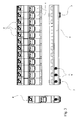
- la figure 3 est une vue de dessus de la représentation de la figure 2 ;
- la figure 4 montre la configuration des deux figures précédentes, les boítiers tronqués de l'invention étant à présent connectés au bloc amovible de manière à réaliser un groupement compact, assemblable à un appareil modulaire classique ;
- la figure 5 représente une configuration possible des éléments de connexion électrique aval, c'est-à-dire ceux qui réalisent la connexion entre le bloc amovible et les appareils à boítiers tronqués ; et
- la figure 6 est une variante de ces mêmes moyens de connexion électrique aval.
- Figure 1 shows a side view of an electrical device according to the invention, the removable block is simply shown schematically by its outline;
- Figure 2 is an exploded perspective view of a group of truncated housings of electrical devices with a single removable block, and connectable to a traditional modular device;
- Figure 3 is a top view of the representation of Figure 2;
- Figure 4 shows the configuration of the previous two figures, the truncated housings of the invention now being connected to the removable block so as to produce a compact grouping, which can be assembled with a conventional modular device;
- Figure 5 shows a possible configuration of the downstream electrical connection elements, that is to say those which make the connection between the removable block and the devices with truncated housings; and
- Figure 6 is a variant of these same downstream electrical connection means.
En référence à la figure 1, l'appareil électrique de l'invention, portant la référence générale (1) comporte au moins un boítier tronqué (2) contenant le noyau fonctionnel et un bloc amovible (3) séparables/emboítables mécaniquement et électriquement grâce à des moyens de connexion par exemple opérables sans outil. Le boítier tronqué (2) intègre les fonctions électriques essentielles de l'appareil électrique (1).Referring to Figure 1, the electrical apparatus of the invention, bearing the general reference (1) comprises at least one truncated case (2) containing the functional core and a removable block (3) separable / nestable mechanically and electrically by means of connection by example operable without tools. The truncated case (2) integrates the functions essential electrical components of the electrical appliance (1).
Ensemble, ledit boítier tronqué (2) et le bloc amovible (3) constituent un appareil électrique dont les dimensions extérieures recréent le volume des appareils électriques modulaires traditionnels. Dans l'exemple représenté en figure 1, le bloc amovible (3) se développe depuis la façade (4) du produit jusqu'à sa semelle (5), et sur la totalité de la largeur de l'appareil, et il inclut dès lors la face dans laquelle débouchent les moyens de connexion d'entrée. L'emboítement du bloc amovible (3) sur le boítier tronqué (2) est notamment rendu possible par la complémentarité des formes en vis-à-vis de ces deux parties.Together, said truncated housing (2) and the removable block (3) constitute a electrical device whose external dimensions recreate the volume of traditional modular electrical appliances. In the example shown in Figure 1, the removable block (3) develops from the front (4) of the product up to its sole (5), and over the entire width of the device, and it includes therefore the face into which the input connection means open. The fitting of the removable block (3) on the truncated case (2) is in particular made possible by the complementarity of the forms opposite these two parts.
Cet emboítement, ainsi que la séparation, peuvent être réalisés sans outil, les moyens de connexion mécanique et électrique étant conçus à cet effet, d'une manière connue en soi.This nesting, as well as separation, can be achieved without tools, the mechanical and electrical connection means being designed for this purpose, in a manner known per se.
La figure 2 montre un exemple d'une série de noyaux fonctionnels, représentés par leur boítier tronqué (2), destinés à coopérer avec un seul bloc amovible (3), par conséquent d'une longueur adaptée à la somme des largeurs des modules (2). Le groupement constitué par les boítiers tronqués (2) connectés au bloc amovible (3) est ensuite destiné à être accolé, sur un rail support, à un appareil modulaire classique (6). La configuration représentée est destinée à être utilisée dans un circuit triphasé, et les moyens de connexion d'entrée (8) sont par conséquent au nombre de trois. Ces moyens de connexion sont en l'occurrence des cages à vis de serrage traditionnelles, lesdites vis étant accessibles via des orifices (9) disposés en partie supérieure du bloc (3) dans le prolongement de la façade (4). Les moyens de connexion aval, destinés à raccorder électriquement ledit bloc (3) aux boítiers tronqués (2), ne sont pas visibles sur cette figure. Ils sont prévus pour s'insérer dans les orifices (11) représentés sur les petits côtés latéraux desdits boítiers tronqués (2) faisant face au bloc (3).Figure 2 shows an example of a series of functional kernels, represented by their truncated housing (2), intended to cooperate with a single block removable (3), therefore of a length adapted to the sum of the module widths (2). The group consisting of truncated boxes (2) connected to the removable block (3) is then intended to be attached, on a rail support, to a conventional modular device (6). The configuration shown is intended to be used in a three-phase circuit, and the means of there are therefore three input connections (8). These means in this case are traditional clamping screw cages, said screws being accessible via orifices (9) arranged in the upper part of the block (3) in the extension of the facade (4). Connection means downstream, intended to electrically connect said block (3) to truncated housings (2), are not visible in this figure. They are intended to fit into the holes (11) shown on the short side sides of said truncated housings (2) facing the block (3).
L'un des avantages présentés par le bloc amovible (3) consiste en la possibilité de mutualiser des fonctions, comme déjà indiqué. En l'espèce, il est à noter que ce bloc (3), destiné à coopérer avec 12 boítiers de largeur correspondant à un module, ne comporte que deux loquets (7) de fixation au rail de montage. En d'autres termes, les encoches de fixation (apparaissant notamment en figure 1) situées, dans le boítier tronqué, au niveau de la semelle (5), sont au nombre de 12, une par produit, et ne coopèrent qu'avec deux loquets (7). Ceci conduit bien évidemment à un gain financier, par économie de pièces et par simplification du montage, qui est non négligeable en référence à la quantité d'appareils produits.One of the advantages presented by the removable block (3) consists in the possibility of sharing functions, as already indicated. In this case, it is note that this block (3), intended to cooperate with 12 boxes of width corresponding to a module, has only two latches (7) for fixing to the mounting rail. In other words, the fixing notches (appearing especially in Figure 1) located in the truncated housing, at the sole (5), there are 12, one per product, and only cooperate with two latches (7). This obviously leads to financial gain, by saving parts and simplifying assembly, which is not negligible with reference to the quantity of devices produced.
La figure 3, présentant une configuration identique à celle de la figure 2, rend plus manifeste le type de connexion électrique aval utilisé pour procéder au raccordement du bloc amovible (3) aux boítiers tronqués (2). Il s'agit en l'occurrence de plots d'allure circulaire (10) destinés à s'insérer dans les orifices précités (11), et qui seront décrits plus en détail en référence à la figure 5. Ces plots circulaires (10) n'ont cependant qu'une fonction mécanique de connexion et de guidage, la connexion électrique étant réalisée par une languette disposée à l'intérieur desdits plots (10).FIG. 3, having a configuration identical to that of FIG. 2, makes more visible the type of downstream electrical connection used to make to the connection of the removable block (3) to the truncated boxes (2). This is in the occurrence of circular-looking studs (10) intended to be inserted in the aforementioned holes (11), which will be described in more detail with reference to the figure 5. These circular studs (10), however, only have a mechanical function of connection and guidance, the electrical connection being made by a tongue arranged inside said studs (10).
L'objet de la figure 4 est simplement de montrer qu'une fois assemblés, le bloc amovible (3) et les boítiers tronqués (2) présentent un profil transversal qui est équivalent à celui de l'appareil modulaire classique (6). De tels appareils classiques peuvent donc être accolés de part et d'autre du groupement formé par ledit bloc (3) fixé au boítier tronqué (2). La nouvelle configuration n'empiète pas sur les espaces traditionnellement dévolus aux conducteurs externes.The object of Figure 4 is simply to show that once assembled, the removable block (3) and the truncated housings (2) have a transverse profile which is equivalent to that of the conventional modular device (6). Such conventional devices can therefore be placed on either side of the group formed by said block (3) fixed to the truncated housing (2). The new configuration does not encroach on the spaces traditionally devoted to external conductors.
La figure 5 montre le bloc amovible (3) utilisé dans les figures 2 à 4, mais selon une orientation opposée. Les plots (10) entourent bien des languettes de connexion électrique (12), qui sont prévues pour s'enficher dans des lames ressort disposées dans les boítiers tronqués (2), et débouchant au niveau des orifices (11).Figure 5 shows the removable block (3) used in Figures 2 to 4, but in an opposite orientation. The studs (10) surround many tabs electrical connection (12), which are designed to be inserted in blades spring arranged in the truncated housings (2), and emerging at the holes (11).
La figure 6 constitue une variante possible au système de connexion électrique aval de la figure 5, selon laquelle les lames (12) sont cette fois insérées entre deux murets parallèles (13, 13'). Ces murets (13, 13'), autant que les plots cylindriques (10), visent à protéger l'utilisateur contre tout contact accidentel sur les languettes, selon les normes de sécurité en vigueur.FIG. 6 constitutes a possible variant of the connection system downstream of Figure 5, according to which the blades (12) are this time inserted between two parallel low walls (13, 13 '). These low walls (13, 13 '), as much that the cylindrical studs (10) aim to protect the user against any contact accidental on the tabs, according to the safety standards in force.
Les figures précédentes ont montré l'association d'un bloc amovible (3) avec plusieurs boítiers tronqués de largeur représentant un module traditionnel du type de l'appareil électrique (6). Il est cependant clair que le choix d'un bloc amovible ne préjuge en aucune façon de la sélection des boítiers qui peuvent y être rattachés. Ainsi, selon les fonctions électriques, les produits disponibles, le pas spécifique des moyens de connexion aval, etc., il sera possible d'intégrer des modules dont la largeur est égale à un sous-multiple ou à un multiple du pas modulaire.The previous figures showed the association of a removable block (3) with several truncated width boxes representing a module traditional type of electrical appliance (6). However, it is clear that the choice of a removable block does not prejudge in any way the selection of boxes that can be attached to it. Thus, depending on the electrical functions, the available products, the specific pitch of the downstream connection means, etc., it it will be possible to integrate modules whose width is equal to a submultiple or a multiple of the modular step.
Dans la configuration représentée aux figures 2 à 5, le pas des moyens de connexion aval est égal au pas des moyens de connexion d'entrée (8). Il ne s'agit bien entendu que d'un cas très particulier, le but principal du bloc amovible (3) étant de réaliser une décorrélation entre le pas amont des moyens de connexion d'entrée et le pas aval. Cet objectif doit être rempli sans pour autant briser la compatibilité avec les appareils modulaires électriques existants, quelle que soit la taille du bloc amovible (3).In the configuration shown in FIGS. 2 to 5, the pitch of the means of downstream connection is equal to the pitch of the input connection means (8). He ... not of course this is a very special case, the main purpose of the block removable (3) being to achieve a decorrelation between the upstream pitch of input connection means and the downstream step. This objective must be fulfilled without however break compatibility with modular electrical devices existing, regardless of the size of the removable block (3).
Comme on l'a déjà mentionné, outre la mutualisation des moyens de fixation au rail, ainsi que celle des moyens de connexion d'entrée, qui découle de l'unicité de ceux-ci pour chaque phase et/ou le neutre, il est également possible d'introduire des éléments supplémentaires dans le bloc amovible :
- un interrupteur différentiel ;
- un voyant de mise sous tension ;
- un système parafoudre ; etc.
- a differential switch;
- a power-on indicator;
- a lightning arrester system; etc.
Ces possibilités, conjuguées avec le choix du pas des moyens de connexion aval, et avec différentes dimensions disponibles du bloc amovible, permettent de réaliser avec souplesse et facilement un très grand nombre de configurations, au gré de l'utilisateur.These possibilities, combined with the choice of the step of the means of downstream connection, and with different available dimensions of the removable block, allow a large number of configurations, at the user's discretion.
Claims (20)
Priority Applications (3)
| Application Number | Priority Date | Filing Date | Title |
|---|---|---|---|
| DE60227086T DE60227086D1 (en) | 2002-12-20 | 2002-12-20 | Electrical device, for example modular electrical device with a two-part housing |
| AT02360377T ATE398334T1 (en) | 2002-12-20 | 2002-12-20 | ELECTRICAL DEVICE, FOR EXAMPLE MODULAR ELECTRICAL DEVICE WITH A TWO-PIECE HOUSING |
| EP02360377A EP1432001B1 (en) | 2002-12-20 | 2002-12-20 | Electrical apparatus, preferably modular, having a two-part housing |
Applications Claiming Priority (1)
| Application Number | Priority Date | Filing Date | Title |
|---|---|---|---|
| EP02360377A EP1432001B1 (en) | 2002-12-20 | 2002-12-20 | Electrical apparatus, preferably modular, having a two-part housing |
Publications (2)
| Publication Number | Publication Date |
|---|---|
| EP1432001A1 true EP1432001A1 (en) | 2004-06-23 |
| EP1432001B1 EP1432001B1 (en) | 2008-06-11 |
Family
ID=32338220
Family Applications (1)
| Application Number | Title | Priority Date | Filing Date |
|---|---|---|---|
| EP02360377A Expired - Lifetime EP1432001B1 (en) | 2002-12-20 | 2002-12-20 | Electrical apparatus, preferably modular, having a two-part housing |
Country Status (3)
| Country | Link |
|---|---|
| EP (1) | EP1432001B1 (en) |
| AT (1) | ATE398334T1 (en) |
| DE (1) | DE60227086D1 (en) |
Cited By (3)
| Publication number | Priority date | Publication date | Assignee | Title |
|---|---|---|---|---|
| EP1962320A1 (en) * | 2007-02-22 | 2008-08-27 | Hager-Electro SAS | Modular electric appliance in blocks |
| WO2017021623A1 (en) | 2015-07-31 | 2017-02-09 | Hager-Electro Sas | Assembly of mechanically and electrically interconnected electrical device casings |
| FR3094581A1 (en) * | 2019-03-26 | 2020-10-02 | Schneider Electric Industries Sas | POWER SUPPLY AND ELECTRICAL CONNECTION DEVICE FOR A SET OF MODULAR DEVICES MOUNTED ON A MOUNTING BRACKET. |
Citations (7)
| Publication number | Priority date | Publication date | Assignee | Title |
|---|---|---|---|---|
| DE1563832A1 (en) * | 1966-09-07 | 1970-03-05 | Stotz Kontakt Gmbh | Multipole residual current circuit breaker |
| EP0691669A1 (en) * | 1994-07-06 | 1996-01-10 | Schneider Electric Sa | Auxiliary block, in particular condition indicator for circuit breakers |
| FR2779269A1 (en) * | 1998-05-29 | 1999-12-03 | Hager Electro | Coupling device for two attached modular electrical elements |
| EP1014414A1 (en) * | 1998-12-23 | 2000-06-28 | Schneider Electric Industries SA | Electrical apparatus like a circuit breaker or a modular switch |
| EP1085550A2 (en) * | 1999-09-13 | 2001-03-21 | ABBPATENT GmbH | Circuit breaker |
| EP1160944A1 (en) * | 2000-05-31 | 2001-12-05 | Schneider Electric Industries SA | Modular electrical apparatus mountable on an insulated distributor |
| DE10120677A1 (en) * | 2001-04-27 | 2002-11-14 | Siemens Ag | Modular series switch unit has switching module with holder for coupling element for clamping switch mechanism, contact elements, connection arrangement in form of contact module |
-
2002
- 2002-12-20 EP EP02360377A patent/EP1432001B1/en not_active Expired - Lifetime
- 2002-12-20 AT AT02360377T patent/ATE398334T1/en not_active IP Right Cessation
- 2002-12-20 DE DE60227086T patent/DE60227086D1/en not_active Expired - Lifetime
Patent Citations (7)
| Publication number | Priority date | Publication date | Assignee | Title |
|---|---|---|---|---|
| DE1563832A1 (en) * | 1966-09-07 | 1970-03-05 | Stotz Kontakt Gmbh | Multipole residual current circuit breaker |
| EP0691669A1 (en) * | 1994-07-06 | 1996-01-10 | Schneider Electric Sa | Auxiliary block, in particular condition indicator for circuit breakers |
| FR2779269A1 (en) * | 1998-05-29 | 1999-12-03 | Hager Electro | Coupling device for two attached modular electrical elements |
| EP1014414A1 (en) * | 1998-12-23 | 2000-06-28 | Schneider Electric Industries SA | Electrical apparatus like a circuit breaker or a modular switch |
| EP1085550A2 (en) * | 1999-09-13 | 2001-03-21 | ABBPATENT GmbH | Circuit breaker |
| EP1160944A1 (en) * | 2000-05-31 | 2001-12-05 | Schneider Electric Industries SA | Modular electrical apparatus mountable on an insulated distributor |
| DE10120677A1 (en) * | 2001-04-27 | 2002-11-14 | Siemens Ag | Modular series switch unit has switching module with holder for coupling element for clamping switch mechanism, contact elements, connection arrangement in form of contact module |
Cited By (3)
| Publication number | Priority date | Publication date | Assignee | Title |
|---|---|---|---|---|
| EP1962320A1 (en) * | 2007-02-22 | 2008-08-27 | Hager-Electro SAS | Modular electric appliance in blocks |
| WO2017021623A1 (en) | 2015-07-31 | 2017-02-09 | Hager-Electro Sas | Assembly of mechanically and electrically interconnected electrical device casings |
| FR3094581A1 (en) * | 2019-03-26 | 2020-10-02 | Schneider Electric Industries Sas | POWER SUPPLY AND ELECTRICAL CONNECTION DEVICE FOR A SET OF MODULAR DEVICES MOUNTED ON A MOUNTING BRACKET. |
Also Published As
| Publication number | Publication date |
|---|---|
| DE60227086D1 (en) | 2008-07-24 |
| EP1432001B1 (en) | 2008-06-11 |
| ATE398334T1 (en) | 2008-07-15 |
Similar Documents
| Publication | Publication Date | Title |
|---|---|---|
| EP0775375B1 (en) | Low cross-talk network connector | |
| EP1376638B1 (en) | Electromagnetic protection and control assembly | |
| FR2904737A1 (en) | DISTRIBUTION ASSEMBLY FOR ELECTRICAL INSTALLATION | |
| EP1432001B1 (en) | Electrical apparatus, preferably modular, having a two-part housing | |
| EP0726614A1 (en) | Composable electrical interface device | |
| EP0524115B1 (en) | Multiple plug for interconnection, in particular for telephone or computer lines | |
| EP0484243B1 (en) | Low current connector for pre-wiring a building | |
| EP3641063B1 (en) | Device for supplying power and for electrically connecting a contactor to a set of modular electrical units mounted side-by-side on a mounting rail and system comprising such a device | |
| FR2928041A1 (en) | Electric socket for e.g. floor of house, has transverse electric links, each terminating on sides by ends of male and female contacts, where ends are electrically and mechanically protected when ends are not used for lateral juxtaposition | |
| CA2098981A1 (en) | Extension element for electric box | |
| FR3039698B1 (en) | ASSEMBLY OF ELECTRICALLY CONNECTED AND ELECTRICALLY CONNECTED ELECTRICAL EQUIPMENT HOUSINGS | |
| EP1916744B1 (en) | Bridging device with two connection levels allowing the connection of derivation terminals | |
| EP2482385B1 (en) | Electrical appliances provided with a supporting means for a bridging device | |
| EP2408068B1 (en) | Configurable bypass device | |
| EP1713152B1 (en) | Control system for medium voltage electrical equipment | |
| FR2807578A1 (en) | POST OF CHASSIS SIMULTANEOUSLY FORMING DISTRIBUTION AND DISTRIBUTION OF ELECTRICAL ENERGY AT DIFFERENT LEVELS OF DEVICE CONNECTION | |
| FR2725071A1 (en) | DIFFERENTIAL SWITCH ASSOCIATED WITH ONE OR MORE CIRCUIT PROTECTION ELEMENTS SUCH AS FUSE OR CIRCUIT BREAKERS | |
| FR3060223A1 (en) | MODULAR COUNTER TO BE POWERED BY A POWER COMB AND ELECTRICAL ASSEMBLY COMPRISING SUCH A COUNTER AND A DEVICE FOR LOCKING THE COMB IN THE CONNECTION POSITION | |
| FR3020506A1 (en) | TERMINAL OF ELECTRICAL CONNECTION MULTI-CONDUCTORS | |
| FR2800927A1 (en) | ELECTRICAL POWER DISTRIBUTOR FOR PLUG-IN DRAWER AND PLUG-IN DRAWER | |
| FR3094581A1 (en) | POWER SUPPLY AND ELECTRICAL CONNECTION DEVICE FOR A SET OF MODULAR DEVICES MOUNTED ON A MOUNTING BRACKET. | |
| FR2990571A1 (en) | END ASSEMBLY FOR DISTRIBUTION ASSEMBLY FOR ELECTRICAL INSTALLATION | |
| FR2863410A1 (en) | ELECTRICAL CONNECTOR MODULAR FILTER | |
| EP1726019B1 (en) | Overvoltage protection device in common/differential mode of reduced size | |
| FR3107596A1 (en) | Modular load meter |
Legal Events
| Date | Code | Title | Description |
|---|---|---|---|
| PUAI | Public reference made under article 153(3) epc to a published international application that has entered the european phase |
Free format text: ORIGINAL CODE: 0009012 |
|
| AK | Designated contracting states |
Kind code of ref document: A1 Designated state(s): AT BE BG CH CY CZ DE DK EE ES FI FR GB GR IE IT LI LU MC NL PT SE SI SK TR |
|
| AX | Request for extension of the european patent |
Extension state: AL LT LV MK RO |
|
| 17P | Request for examination filed |
Effective date: 20040831 |
|
| 17Q | First examination report despatched |
Effective date: 20041213 |
|
| AKX | Designation fees paid |
Designated state(s): AT BE BG CH CY CZ DE DK EE ES FI FR GB GR IE IT LI LU MC NL PT SE SI SK TR |
|
| GRAP | Despatch of communication of intention to grant a patent |
Free format text: ORIGINAL CODE: EPIDOSNIGR1 |
|
| GRAS | Grant fee paid |
Free format text: ORIGINAL CODE: EPIDOSNIGR3 |
|
| GRAA | (expected) grant |
Free format text: ORIGINAL CODE: 0009210 |
|
| AK | Designated contracting states |
Kind code of ref document: B1 Designated state(s): AT BE BG CH CY CZ DE DK EE ES FI FR GB GR IE IT LI LU MC NL PT SE SI SK TR |
|
| REG | Reference to a national code |
Ref country code: GB Ref legal event code: FG4D Free format text: NOT ENGLISH |
|
| REG | Reference to a national code |
Ref country code: CH Ref legal event code: EP |
|
| REF | Corresponds to: |
Ref document number: 60227086 Country of ref document: DE Date of ref document: 20080724 Kind code of ref document: P |
|
| REG | Reference to a national code |
Ref country code: IE Ref legal event code: FG4D Free format text: LANGUAGE OF EP DOCUMENT: FRENCH |
|
| PG25 | Lapsed in a contracting state [announced via postgrant information from national office to epo] |
Ref country code: FI Free format text: LAPSE BECAUSE OF FAILURE TO SUBMIT A TRANSLATION OF THE DESCRIPTION OR TO PAY THE FEE WITHIN THE PRESCRIBED TIME-LIMIT Effective date: 20080611 Ref country code: SI Free format text: LAPSE BECAUSE OF FAILURE TO SUBMIT A TRANSLATION OF THE DESCRIPTION OR TO PAY THE FEE WITHIN THE PRESCRIBED TIME-LIMIT Effective date: 20080611 |
|
| PG25 | Lapsed in a contracting state [announced via postgrant information from national office to epo] |
Ref country code: AT Free format text: LAPSE BECAUSE OF FAILURE TO SUBMIT A TRANSLATION OF THE DESCRIPTION OR TO PAY THE FEE WITHIN THE PRESCRIBED TIME-LIMIT Effective date: 20080611 Ref country code: NL Free format text: LAPSE BECAUSE OF FAILURE TO SUBMIT A TRANSLATION OF THE DESCRIPTION OR TO PAY THE FEE WITHIN THE PRESCRIBED TIME-LIMIT Effective date: 20080611 |
|
| NLV1 | Nl: lapsed or annulled due to failure to fulfill the requirements of art. 29p and 29m of the patents act | ||
| PG25 | Lapsed in a contracting state [announced via postgrant information from national office to epo] |
Ref country code: PT Free format text: LAPSE BECAUSE OF FAILURE TO SUBMIT A TRANSLATION OF THE DESCRIPTION OR TO PAY THE FEE WITHIN THE PRESCRIBED TIME-LIMIT Effective date: 20081111 Ref country code: ES Free format text: LAPSE BECAUSE OF FAILURE TO SUBMIT A TRANSLATION OF THE DESCRIPTION OR TO PAY THE FEE WITHIN THE PRESCRIBED TIME-LIMIT Effective date: 20080922 Ref country code: SE Free format text: LAPSE BECAUSE OF FAILURE TO SUBMIT A TRANSLATION OF THE DESCRIPTION OR TO PAY THE FEE WITHIN THE PRESCRIBED TIME-LIMIT Effective date: 20080911 Ref country code: CZ Free format text: LAPSE BECAUSE OF FAILURE TO SUBMIT A TRANSLATION OF THE DESCRIPTION OR TO PAY THE FEE WITHIN THE PRESCRIBED TIME-LIMIT Effective date: 20080611 |
|
| REG | Reference to a national code |
Ref country code: IE Ref legal event code: FD4D |
|
| PG25 | Lapsed in a contracting state [announced via postgrant information from national office to epo] |
Ref country code: SK Free format text: LAPSE BECAUSE OF FAILURE TO SUBMIT A TRANSLATION OF THE DESCRIPTION OR TO PAY THE FEE WITHIN THE PRESCRIBED TIME-LIMIT Effective date: 20080611 |
|
| PLBE | No opposition filed within time limit |
Free format text: ORIGINAL CODE: 0009261 |
|
| STAA | Information on the status of an ep patent application or granted ep patent |
Free format text: STATUS: NO OPPOSITION FILED WITHIN TIME LIMIT |
|
| PG25 | Lapsed in a contracting state [announced via postgrant information from national office to epo] |
Ref country code: EE Free format text: LAPSE BECAUSE OF FAILURE TO SUBMIT A TRANSLATION OF THE DESCRIPTION OR TO PAY THE FEE WITHIN THE PRESCRIBED TIME-LIMIT Effective date: 20080611 Ref country code: IE Free format text: LAPSE BECAUSE OF FAILURE TO SUBMIT A TRANSLATION OF THE DESCRIPTION OR TO PAY THE FEE WITHIN THE PRESCRIBED TIME-LIMIT Effective date: 20080611 Ref country code: DK Free format text: LAPSE BECAUSE OF FAILURE TO SUBMIT A TRANSLATION OF THE DESCRIPTION OR TO PAY THE FEE WITHIN THE PRESCRIBED TIME-LIMIT Effective date: 20080611 Ref country code: BG Free format text: LAPSE BECAUSE OF FAILURE TO SUBMIT A TRANSLATION OF THE DESCRIPTION OR TO PAY THE FEE WITHIN THE PRESCRIBED TIME-LIMIT Effective date: 20080911 |
|
| 26N | No opposition filed |
Effective date: 20090312 |
|
| BERE | Be: lapsed |
Owner name: HAGER ELECTRO Effective date: 20081231 |
|
| PG25 | Lapsed in a contracting state [announced via postgrant information from national office to epo] |
Ref country code: MC Free format text: LAPSE BECAUSE OF NON-PAYMENT OF DUE FEES Effective date: 20081231 |
|
| REG | Reference to a national code |
Ref country code: CH Ref legal event code: PL |
|
| GBPC | Gb: european patent ceased through non-payment of renewal fee |
Effective date: 20081220 |
|
| PG25 | Lapsed in a contracting state [announced via postgrant information from national office to epo] |
Ref country code: BE Free format text: LAPSE BECAUSE OF NON-PAYMENT OF DUE FEES Effective date: 20081231 |
|
| PG25 | Lapsed in a contracting state [announced via postgrant information from national office to epo] |
Ref country code: LI Free format text: LAPSE BECAUSE OF NON-PAYMENT OF DUE FEES Effective date: 20081231 Ref country code: CH Free format text: LAPSE BECAUSE OF NON-PAYMENT OF DUE FEES Effective date: 20081231 |
|
| PG25 | Lapsed in a contracting state [announced via postgrant information from national office to epo] |
Ref country code: GB Free format text: LAPSE BECAUSE OF NON-PAYMENT OF DUE FEES Effective date: 20081220 |
|
| PG25 | Lapsed in a contracting state [announced via postgrant information from national office to epo] |
Ref country code: LU Free format text: LAPSE BECAUSE OF NON-PAYMENT OF DUE FEES Effective date: 20081220 Ref country code: CY Free format text: LAPSE BECAUSE OF FAILURE TO SUBMIT A TRANSLATION OF THE DESCRIPTION OR TO PAY THE FEE WITHIN THE PRESCRIBED TIME-LIMIT Effective date: 20080611 |
|
| PG25 | Lapsed in a contracting state [announced via postgrant information from national office to epo] |
Ref country code: TR Free format text: LAPSE BECAUSE OF FAILURE TO SUBMIT A TRANSLATION OF THE DESCRIPTION OR TO PAY THE FEE WITHIN THE PRESCRIBED TIME-LIMIT Effective date: 20080611 |
|
| PG25 | Lapsed in a contracting state [announced via postgrant information from national office to epo] |
Ref country code: GR Free format text: LAPSE BECAUSE OF FAILURE TO SUBMIT A TRANSLATION OF THE DESCRIPTION OR TO PAY THE FEE WITHIN THE PRESCRIBED TIME-LIMIT Effective date: 20080912 |
|
| REG | Reference to a national code |
Ref country code: FR Ref legal event code: PLFP Year of fee payment: 14 |
|
| REG | Reference to a national code |
Ref country code: FR Ref legal event code: PLFP Year of fee payment: 15 |
|
| PGFP | Annual fee paid to national office [announced via postgrant information from national office to epo] |
Ref country code: FR Payment date: 20161130 Year of fee payment: 15 |
|
| PGFP | Annual fee paid to national office [announced via postgrant information from national office to epo] |
Ref country code: IT Payment date: 20161206 Year of fee payment: 15 |
|
| PGFP | Annual fee paid to national office [announced via postgrant information from national office to epo] |
Ref country code: DE Payment date: 20161223 Year of fee payment: 15 |
|
| REG | Reference to a national code |
Ref country code: DE Ref legal event code: R119 Ref document number: 60227086 Country of ref document: DE |
|
| REG | Reference to a national code |
Ref country code: FR Ref legal event code: ST Effective date: 20180831 |
|
| PG25 | Lapsed in a contracting state [announced via postgrant information from national office to epo] |
Ref country code: DE Free format text: LAPSE BECAUSE OF NON-PAYMENT OF DUE FEES Effective date: 20180703 Ref country code: IT Free format text: LAPSE BECAUSE OF NON-PAYMENT OF DUE FEES Effective date: 20171220 Ref country code: FR Free format text: LAPSE BECAUSE OF NON-PAYMENT OF DUE FEES Effective date: 20180102 |