EP1083074A2 - Kraftstoffbehälter - Google Patents
Kraftstoffbehälter Download PDFInfo
- Publication number
- EP1083074A2 EP1083074A2 EP00116744A EP00116744A EP1083074A2 EP 1083074 A2 EP1083074 A2 EP 1083074A2 EP 00116744 A EP00116744 A EP 00116744A EP 00116744 A EP00116744 A EP 00116744A EP 1083074 A2 EP1083074 A2 EP 1083074A2
- Authority
- EP
- European Patent Office
- Prior art keywords
- connecting part
- filler pipe
- fuel tank
- tank chamber
- fastening
- Prior art date
- Legal status (The legal status is an assumption and is not a legal conclusion. Google has not performed a legal analysis and makes no representation as to the accuracy of the status listed.)
- Withdrawn
Links
Images

Classifications
-
- B—PERFORMING OPERATIONS; TRANSPORTING
- B60—VEHICLES IN GENERAL
- B60K—ARRANGEMENT OR MOUNTING OF PROPULSION UNITS OR OF TRANSMISSIONS IN VEHICLES; ARRANGEMENT OR MOUNTING OF PLURAL DIVERSE PRIME-MOVERS IN VEHICLES; AUXILIARY DRIVES FOR VEHICLES; INSTRUMENTATION OR DASHBOARDS FOR VEHICLES; ARRANGEMENTS IN CONNECTION WITH COOLING, AIR INTAKE, GAS EXHAUST OR FUEL SUPPLY OF PROPULSION UNITS IN VEHICLES
- B60K15/00—Arrangement in connection with fuel supply of combustion engines or other fuel consuming energy converters, e.g. fuel cells; Mounting or construction of fuel tanks
- B60K15/03—Fuel tanks
- B60K15/04—Tank inlets
-
- Y—GENERAL TAGGING OF NEW TECHNOLOGICAL DEVELOPMENTS; GENERAL TAGGING OF CROSS-SECTIONAL TECHNOLOGIES SPANNING OVER SEVERAL SECTIONS OF THE IPC; TECHNICAL SUBJECTS COVERED BY FORMER USPC CROSS-REFERENCE ART COLLECTIONS [XRACs] AND DIGESTS
- Y10—TECHNICAL SUBJECTS COVERED BY FORMER USPC
- Y10T—TECHNICAL SUBJECTS COVERED BY FORMER US CLASSIFICATION
- Y10T137/00—Fluid handling
- Y10T137/1624—Destructible or deformable element controlled
- Y10T137/1632—Destructible element
- Y10T137/1654—Separable valve coupling or conduit
-
- Y—GENERAL TAGGING OF NEW TECHNOLOGICAL DEVELOPMENTS; GENERAL TAGGING OF CROSS-SECTIONAL TECHNOLOGIES SPANNING OVER SEVERAL SECTIONS OF THE IPC; TECHNICAL SUBJECTS COVERED BY FORMER USPC CROSS-REFERENCE ART COLLECTIONS [XRACs] AND DIGESTS
- Y10—TECHNICAL SUBJECTS COVERED BY FORMER USPC
- Y10T—TECHNICAL SUBJECTS COVERED BY FORMER US CLASSIFICATION
- Y10T137/00—Fluid handling
- Y10T137/598—With repair, tapping, assembly, or disassembly means
Definitions
- the invention relates to a fuel tank with a on a tank chamber arranged filler pipe, the Filler tube separable from and with the tank chamber is connectable again.
- Such fuel tanks are used in today's motor vehicles frequently used and are known from practice.
- the filler pipe of the fuel tank known from practice is via a molded hose with the tank chamber connected.
- the tank chamber With maintenance, for example in the Tank chamber arranged components of a fuel delivery unit the tank chamber can be removed after loosening disassemble the molded hose separately from the filler pipe.
- the separation of the tank base from the mostly very expansive designed filler tube has the advantage that a complex disassembly when dismantling the tank chamber for example the rear axle of the motor vehicle mostly can be avoided.
- a disadvantage of the known fuel tank is that fuel vapors pass through the joint of the molded hose on the filler pipe and the Tank chamber can get into the area.
- the invention is based on the problem of a fuel tank of the type mentioned at the beginning that there is an escape of fuel vapors into the environment largely prevented.
- tank chamber and the filler pipe are made in one piece or are welded and that the unit from filler pipe and the tank chamber a section provided for cutting has and in the adjacent areas is designed for fastening a connecting part.
- the fuel tank according to the invention has this design when new, no connection points between the tank chamber and the filler pipe.
- the connection the unit from the tank chamber and filler pipe can, however separately for maintenance of the fuel tank according to the invention and the tank chamber can be easily dismantled. Subsequently the components by means of a connecting part connected with each other.
- the fuel tank is new will allow fuel to escape from the Avoid fuel tanks reliably.
- Fuel tank like the well-known fuel tank Sealing points on the connecting part. This will be a Escape of fuel from the invention Fuel tanks largely avoided.
- the one-piece Manufacturing of the tank chamber with the filler pipe can be done by their manufacture in a common form or by welding or gluing.
- Tolerance compensation between the separate areas can be according to another advantageous development easily achieve the invention when the connector is designed as a piece of hose.
- the unit consisting of filler pipe and tank chamber can be adjusted according to an advantageous development of the invention simple cut through if the unit consists of filler pipe and Tank chamber in the section intended for cutting has a circumferential groove.
- Another advantage of this Design is that the groove as a mark serves and thus the risk of incorrect cutting, which then has a faulty seat of the connecting part may result in reduced.
- a reliable hold of the connecting part can be according to another advantageous development of the invention just make sure if the unit is out of filler tube and tank chamber on its outside circumferential, radial protruding projections for fastening the connecting part having.
- the projections will also the tightness of the fuel tank increases.
- a clash of through separation of unity Filling tube and tank chamber resulting ends can be according to another advantageous development of the invention Avoid reliably if the unit is made of filler tube and tank chamber two spaced apart Has separation points and if the separation points at their from each other facing sides each to one for attachment adjoin the area provided for the connecting part. This bridges the connecting part from the Fuel tank separated area and serves as a spacer and as tolerance compensation between the separation points.
- a tolerance compensation between the tank chamber and the Filler tube can be advantageous according to another Develop the invention simply in that the unit consisting of filler pipe and tank chamber in the for Cut provided area has a bellows.
- a string of elastic, to compensate for Tolerances provided can be according to another avoid advantageous further development of the invention, if the bellows between two for attachment arranged areas of the connecting part is. As a result, the fuel tank initially has the Bellows as tolerance compensation. In the event of maintenance the bellows removed and replaced by the connector.
- the area is capable particularly high tensile forces to increase the invention, if the intended for fastening the connecting part Areas have a circumferential bead, and if the connecting part is designed as corresponding to the beads Shaped hose is formed.
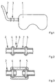
- Figure 1 schematically shows a fuel tank a tank chamber 1 for collecting fuel and a filler tube 2 welded to it.
- the filler tube 2 has near the tank chamber 1, one intended for severing Section 3.
- Figure 2 shows the filler pipe 2 in the for severing provided section 3 in longitudinal section.
- the filler pipe 2 has two on the section to be cut 3 adjacent beads 4, 5. Near the beads 4, 5 are in the filler tube 2 two grooves 6, 7 arranged.
- the grooves 6, 7 serve as a mark when cutting the filler pipe 2 if the tank chamber 1 shown in FIG. 1 to be dismantled.
- Figure 3 shows the section of Filler tube 2 after cutting in the area of the grooves 6, 7 and an assembly of a connecting part 8.
- Das Connecting part 8 is designed as a molded hose and keeps the beads 4, 5 at a distance. Still reaching behind the connecting part 8, the beads 4, 5 and seals that Fill pipe 2 from.
- Figure 4 shows a further embodiment of the filler pipe 2 with a section provided for cutting 9 and with a bellows 10.
- To the side of the bellows 10 are areas for mounting a shown in Figure 5 Connection part 11 arranged.
- the areas for assembly of the connecting part formed here as a piece of tubing 11 have radially projecting projections 12, 13 on.
- the projections 12, 13 are used for mechanical fastening of the connecting part 11 and the seal of the Filler tube 2.
- Near the bellows 10 has the filler tube 2 grooves 14, 15 as a mark for cutting.
Landscapes
- Engineering & Computer Science (AREA)
- Life Sciences & Earth Sciences (AREA)
- Sustainable Development (AREA)
- Sustainable Energy (AREA)
- Chemical & Material Sciences (AREA)
- Combustion & Propulsion (AREA)
- Transportation (AREA)
- Mechanical Engineering (AREA)
- Cooling, Air Intake And Gas Exhaust, And Fuel Tank Arrangements In Propulsion Units (AREA)
Abstract
Description
- Fig.1
- schematisch einen erfindungsgemäßen Kraftstoffbehälter,
- Fig.2
- einen zum Durchtrennen eines Einfüllrohrs des Kraftstoffbehälters aus Figur 1 vorgesehenen Abschnitt im Längsschnitt,
- Fig.3
- das Einfüllrohr aus Figur 2 nach einer Montage des Verbindungsteils,
- Fig.4
- eine weitere Ausführungsform eines Einfüllrohrs,
- Fig.5
- das Einfüllrohr aus Figur 4 nach einer Montage des Verbindungsteils.
Claims (8)
- Kraftstoffbehälter mit einem an einer Tankkammer angeordneten Einfüllrohr, wobei das Einfüllrohr von der Tankkammer trennbar und mit dieser wieder verbindbar ist, dadurch gekennzeichnet, daß die Tankkammer (1) und das Einfüllrohr (2) einstückig gefertigt oder verschweißt sind und daß die Einheit aus Einfüllrohr (2) und Tankkammer (1) einen zum Durchtrennen vorgesehenen Abschnitt (3, 9) aufweist und in den daran angrenzenden Bereichen zur Befestigung eines Verbindungsteils (8, 11) gestaltet ist
- Kraftstoffbehälter nach Anspruch 1, dadurch gekennzeichnet, daß das Verbindungsteil (11) als Schlauchstück ausgebildet ist.
- Kraftstoffbehälter nach Anspruch 1 oder 2, dadurch gekennzeichnet, daß die Einheit aus Einfüllrohr (2) und Tankkammer (1) in dem zum Durchtrennen vorgesehenen Abschnitt (3, 9) eine umlaufende Rille (6, 7, 14, 15) hat.
- Kraftstoffbehälter nach zumindest einem der vorhergehenden Ansprüche, dadurch gekennzeichnet, daß die Einheit aus Einfüllrohr (2) und Tankkammer (1) auf ihrer Außenseite umlaufende, radial hervorstehende Vorsprünge (12, 13) zur Befestigung des Verbindungsteils (8, 11) aufweist.
- Kraftstoffbehälter nach zumindest einem der vorhergehenden Ansprüche, dadurch gekennzeichnet, daß die Einheit aus Einfüllrohr (2) und Tankkammer (1) zwei voneinander beabstandete Trennstellen (Rille 6, 7, 14, 15) hat und daß die Trennstellen (Rille 6, 7, 14, 15) an ihren voneinander abgewandten Seiten jeweils an einen zur Befestigung des Verbindungsteils (8, 11) vorgesehenen Bereich angrenzen.
- Kraftstoffbehälter nach zumindest einem der vorhergehenden Ansprüche, dadurch gekennzeichnet, daß die Einheit aus Einfüllrohr (2) und Tankkammer (1) in dem zum Durchtrennen vorgesehenen Bereich einen Faltenbalg (10) aufweist.
- Kraftstoffbhälter nach zumindest einem der vorhergehenden Ansprüche, dadurch gekennzeichnet, daß der Faltenbalg (10) zwischen zwei zur Befestigung des Verbindungsteils (11) vorgesehenen Bereichen angeordnet ist.
- Kraftstoffbehälter nach zumindest einem der vorhergehenden Ansprüche, dadurch gekennzeichnet, daß die zur Befestigung des Verbindungsteils (8) vorgesehenen Bereiche einen umlaufenden Wulst (4, 5) aufweisen, und daß das Verbindungsteil (8) als den Wulsten (4, 5) entsprechend gestalteter Formschlauch ausgebildet ist.
Applications Claiming Priority (2)
| Application Number | Priority Date | Filing Date | Title |
|---|---|---|---|
| DE19943260 | 1999-09-10 | ||
| DE19943260A DE19943260A1 (de) | 1999-09-10 | 1999-09-10 | Kraftstoffbehälter |
Publications (2)
| Publication Number | Publication Date |
|---|---|
| EP1083074A2 true EP1083074A2 (de) | 2001-03-14 |
| EP1083074A3 EP1083074A3 (de) | 2004-11-10 |
Family
ID=7921457
Family Applications (1)
| Application Number | Title | Priority Date | Filing Date |
|---|---|---|---|
| EP00116744A Withdrawn EP1083074A3 (de) | 1999-09-10 | 2000-08-03 | Kraftstoffbehälter |
Country Status (5)
| Country | Link |
|---|---|
| US (1) | US6378549B1 (de) |
| EP (1) | EP1083074A3 (de) |
| JP (1) | JP2001113966A (de) |
| KR (1) | KR20010050380A (de) |
| DE (1) | DE19943260A1 (de) |
Cited By (1)
| Publication number | Priority date | Publication date | Assignee | Title |
|---|---|---|---|---|
| US7628178B2 (en) | 2003-08-19 | 2009-12-08 | Daimler Ag | Safety device |
Families Citing this family (5)
| Publication number | Priority date | Publication date | Assignee | Title |
|---|---|---|---|---|
| US6591871B2 (en) * | 2001-09-13 | 2003-07-15 | Dayco Products, Llc | Low permeation polybutylene terephthalate and polybutylene naphthalate fuel and vapor tubes |
| US6758499B1 (en) * | 2002-07-02 | 2004-07-06 | At&T Corp. | System and method for repairing a conduit |
| JP2005098229A (ja) * | 2003-09-25 | 2005-04-14 | Toyoda Gosei Co Ltd | 燃料タンク用継手 |
| US9310014B2 (en) * | 2009-12-07 | 2016-04-12 | Smart Pipe Company L.P. | Systems and methods for making pipe, and method of installing the pipe in a pipeline |
| US8776835B2 (en) * | 2012-12-05 | 2014-07-15 | Hamilton Sundstrand Corporation | Fluid duct with improved connecting bead |
Family Cites Families (17)
| Publication number | Priority date | Publication date | Assignee | Title |
|---|---|---|---|---|
| US481192A (en) * | 1892-08-23 | Stop mechanism for turret-lathes | ||
| US1558503A (en) * | 1921-10-06 | 1925-10-27 | John G Pressler | Hose connection for automobile engines and radiators |
| US1921809A (en) * | 1931-11-06 | 1933-08-08 | Crain Earl | Gas pipe stop |
| US3875970A (en) * | 1971-03-25 | 1975-04-08 | Manostat Corp | Tubing |
| US3895177A (en) * | 1973-03-12 | 1975-07-15 | Specialty Connector Corp | Flexible metal conduit with end connectors and method of making the same |
| JPS5542980Y2 (de) * | 1975-09-02 | 1980-10-08 | ||
| JPS60154910A (ja) * | 1984-01-24 | 1985-08-14 | Toyota Motor Corp | 自動車の燃料タンク構造 |
| GB8403370D0 (en) * | 1984-02-08 | 1984-03-14 | Lucas Ind Plc | Hydraulic fluid connector |
| US4828557A (en) * | 1984-04-06 | 1989-05-09 | Persidsky Maxim D | Sterile connector and method |
| JPS60231092A (ja) * | 1984-04-27 | 1985-11-16 | 日産自動車株式会社 | 配管連結装置 |
| JPS60255531A (ja) * | 1984-05-30 | 1985-12-17 | Nissan Shatai Co Ltd | 自動車用燃料タンク |
| US4872471A (en) * | 1988-09-21 | 1989-10-10 | Schneider Peter J | Separable and breakaway valve interconnecting a fluid line |
| DE3916993A1 (de) * | 1989-05-24 | 1990-11-29 | Bayerische Motoren Werke Ag | Einfuellrohr fuer kraftstoffbehaelter, insbesondere fuer kraftfahrzeuge |
| US5050911A (en) * | 1990-01-05 | 1991-09-24 | Kaiser Aerospace & Electronics Corporation | Breakaway coupling |
| US5250041A (en) * | 1992-01-16 | 1993-10-05 | Fresenius Usa, Inc. | Tubing administration set for use in peritoneal dialysis |
| US5343902A (en) * | 1992-09-18 | 1994-09-06 | Solvay Automotive, Inc. | Internal gas removal system for fuel tank and method of making thereof |
| DE19547876A1 (de) * | 1995-12-21 | 1997-06-26 | Bosch Gmbh Robert | Kraftstoffleitung für Kraftstoffördereinrichtungen von Kraftfahrzeugen |
-
1999
- 1999-09-10 DE DE19943260A patent/DE19943260A1/de not_active Withdrawn
-
2000
- 2000-08-03 EP EP00116744A patent/EP1083074A3/de not_active Withdrawn
- 2000-08-29 US US09/649,980 patent/US6378549B1/en not_active Expired - Fee Related
- 2000-09-07 JP JP2000272068A patent/JP2001113966A/ja active Pending
- 2000-09-07 KR KR1020000053139A patent/KR20010050380A/ko not_active Withdrawn
Non-Patent Citations (1)
| Title |
|---|
| None |
Cited By (2)
| Publication number | Priority date | Publication date | Assignee | Title |
|---|---|---|---|---|
| US7628178B2 (en) | 2003-08-19 | 2009-12-08 | Daimler Ag | Safety device |
| DE10338065B4 (de) * | 2003-08-19 | 2012-12-20 | Daimler Ag | Sicherheitsvorrichtung |
Also Published As
| Publication number | Publication date |
|---|---|
| EP1083074A3 (de) | 2004-11-10 |
| JP2001113966A (ja) | 2001-04-24 |
| KR20010050380A (ko) | 2001-06-15 |
| DE19943260A1 (de) | 2001-03-15 |
| US6378549B1 (en) | 2002-04-30 |
Similar Documents
| Publication | Publication Date | Title |
|---|---|---|
| DE3005790A1 (de) | Rohrkupplung | |
| DE19742361C2 (de) | Elastischer Gelenkkörper | |
| EP3849827B1 (de) | Verbindungssystem, kupplungssystem und verfahren zur verbindung eines zugfahrzeugs mit einem auflieger | |
| DE60319953T2 (de) | Sicherungsringvorrichtung für eine radnabenvorrichtung | |
| EP1357299B1 (de) | Pneumatisches Schieberventil mit einem zweiteiligen Ventilgehäuse aus Kunststoff | |
| DE3031870A1 (de) | Kassetten-dichtung | |
| DE69411326T2 (de) | Vorrichtung und Verfahren zur Befestigung einer Achse auf einem Aufhängungslenker | |
| EP2046611A1 (de) | Hubeinrichtung | |
| DE102018129434B4 (de) | Fahrzeugkarosseriestruktur | |
| EP1006014B1 (de) | Kraftstoffbehälter und Verfahren zur Montage von Leitungen in einem Kraftstoffbehälter | |
| WO2020182356A1 (de) | Blattfederlager und kraftfahrzeugradaufhängung mit einem solchen | |
| EP1325223B1 (de) | Saugrohr für eine brennkraftmaschine mit mindestens zwei verschweissten schalen | |
| EP1083074A2 (de) | Kraftstoffbehälter | |
| EP1222407A1 (de) | Kugelgelenk | |
| EP1650055A2 (de) | Antriebsbrücke | |
| DE4402946C2 (de) | Elastische Lagerung für Kettenbolzen in Gleisketten | |
| DE3008287A1 (de) | Bolzen fuer schubstangen | |
| DE20104406U1 (de) | Kraftfahrzeugsichtscheibenspritzwasserzuführanordnung | |
| DE69730933T2 (de) | Feste Kupplungseinrichtung für zwei Wellen | |
| EP0579141B1 (de) | Automatisch montierbare Steckkupplung für Leitungsschläuche in Kraftfahrzeugen | |
| DE102007044973A1 (de) | Fahrzeugdrehfederachse | |
| EP0307971B1 (de) | Kupplungsmuffe zum Verbinden von zwei Rohrleitungsenden | |
| DE3148997A1 (de) | Flexible rohrkupplung | |
| DE2322253A1 (de) | Gelenk-kupplung fuer gestaenge | |
| DE4204973C2 (de) | Verfahren zum Herstellen einer Gelenkscheibe sowie eine Gelenkscheibe zum Verbinden von Wellenflanschen |
Legal Events
| Date | Code | Title | Description |
|---|---|---|---|
| PUAI | Public reference made under article 153(3) epc to a published international application that has entered the european phase |
Free format text: ORIGINAL CODE: 0009012 |
|
| AK | Designated contracting states |
Kind code of ref document: A2 Designated state(s): AT BE CH CY DE DK ES FI FR GB GR IE IT LI LU MC NL PT SE |
|
| AX | Request for extension of the european patent |
Free format text: AL;LT;LV;MK;RO;SI |
|
| RAP1 | Party data changed (applicant data changed or rights of an application transferred) |
Owner name: SIEMENS AKTIENGESELLSCHAFT |
|
| PUAL | Search report despatched |
Free format text: ORIGINAL CODE: 0009013 |
|
| AK | Designated contracting states |
Kind code of ref document: A3 Designated state(s): AT BE CH CY DE DK ES FI FR GB GR IE IT LI LU MC NL PT SE |
|
| AX | Request for extension of the european patent |
Extension state: AL LT LV MK RO SI |
|
| 17P | Request for examination filed |
Effective date: 20041004 |
|
| 17Q | First examination report despatched |
Effective date: 20050310 |
|
| AKX | Designation fees paid |
Designated state(s): AT BE CH CY DE DK ES FI FR GB GR IE IT LI LU MC NL PT SE |
|
| STAA | Information on the status of an ep patent application or granted ep patent |
Free format text: STATUS: THE APPLICATION IS DEEMED TO BE WITHDRAWN |
|
| 18D | Application deemed to be withdrawn |
Effective date: 20060418 |