EP1082735B1 - Variable induktivität - Google Patents
Variable induktivität Download PDFInfo
- Publication number
- EP1082735B1 EP1082735B1 EP99921775A EP99921775A EP1082735B1 EP 1082735 B1 EP1082735 B1 EP 1082735B1 EP 99921775 A EP99921775 A EP 99921775A EP 99921775 A EP99921775 A EP 99921775A EP 1082735 B1 EP1082735 B1 EP 1082735B1
- Authority
- EP
- European Patent Office
- Prior art keywords
- core
- center leg
- cross
- legs
- outer legs
- Prior art date
- Legal status (The legal status is an assumption and is not a legal conclusion. Google has not performed a legal analysis and makes no representation as to the accuracy of the status listed.)
- Expired - Lifetime
Links
Images


Classifications
-
- H—ELECTRICITY
- H01—ELECTRIC ELEMENTS
- H01F—MAGNETS; INDUCTANCES; TRANSFORMERS; SELECTION OF MATERIALS FOR THEIR MAGNETIC PROPERTIES
- H01F27/00—Details of transformers or inductances, in general
- H01F27/24—Magnetic cores
-
- H—ELECTRICITY
- H01—ELECTRIC ELEMENTS
- H01F—MAGNETS; INDUCTANCES; TRANSFORMERS; SELECTION OF MATERIALS FOR THEIR MAGNETIC PROPERTIES
- H01F29/00—Variable transformers or inductances not covered by group H01F21/00
- H01F29/14—Variable transformers or inductances not covered by group H01F21/00 with variable magnetic bias
- H01F2029/143—Variable transformers or inductances not covered by group H01F21/00 with variable magnetic bias with control winding for generating magnetic bias
Definitions
- This invention relates to a variable inductor and a method of varying the inductance of an inductive circuit element.
- the invention relates to a variable inductor in which the inductance of an inductive circuit element is varied by means of an electrical signal.
- Variable inductors are of use in many circuit applications including magnetic amplifiers which vary the inductance of a circuit element to regulate power and resonant circuits which vary the inductance of circuit elements to vary the resonant frequency of the circuit.
- the simplest way to obtain a variable inductor is by mechanical movement of a connector along an inductive element.
- FIG. 1 illustrates a current controlled variable inductor of the above-mentioned prior art in which the inductance L 14 of center winding 14 is controlled by the current Ic delivered to outer control windings 12 and 13.
- FIG. 1 shows a magnetic core 11, consisting of a magnetic material that can be saturated, with three legs 15, 16 and 17.
- the outer legs 15 and 17 have identical windings 12 and 13 that are connected in series as shown.
- Control windings 12 and 13 are wound and connected in such a way that the magnetic flux ⁇ c in respective legs 15 and 17 of the core arising from the control current Ic through the outer windings 12 and 13 is equal and points in opposite directions.
- the opposing magnetic flux ⁇ c results in cancellation in the center leg 16 of the core.
- the flux cancellation prevents coupling of AC signals between the center winding 14 and the series control windings 12 and 13.
- the magnetic path for center winding 14 includes outer legs 15 and 17, center legs 16 and the connecting portions 18-21. If the control current Ic through windings 12 and 13 becomes large enough to saturate the legs 15 and 17 of the core, the inductance L 14 of center winding 14 decreases because a portion of the magnetic path for the center winding 14 is saturated. The higher the control current Ic becomes, the lower the inductance L 14 becomes. However, the center leg 16 will not be saturated due to the control current Ic.
- the minimum inductance L 14 is limited by the number of turns and the magnetic permeability of the core material of the center leg 16.
- Another undesirable side effect of the prior art circuit of FIG. 1 is that the inductance of each of the series connected control windings 12 and 13 changes substantially with a change in the value of the control current Ic.
- the inductances of the control windings 12 and 13 change by a greater amount than the inductance of the center winding 14. This condition establishes significant limitations when the prior art variable inductor is part of a regulation loop.
- the inductor of the prior art circuit FIG. 1 has a limited variation range or requires a very high control current in the order of about 0 to 500 mA.
- the voltage across each control winding 12 and 13 and the parasitic capacitances of control windings 12 and 13 limit the winding ratio and/or the operating frequency.
- the inductance of the control windings 12 and 13 changes substantially with the control current Ic.
- U.K. Patent 715,610 discloses variable inductive elements having saturable cores.
- the U.K. '610 variable inductors are illustrated in FIGS. 2A and 2B.
- the variable inductor of FIG. 2A has series windings on the outer legs of a three leg core, and accordingly is similar to FIG. 1 above.
- FIG. 2B illustrates parallel windings on the outer legs of a three leg core and a control winding on the center leg of the core.
- Patents to set the magnetic cross-section of the center leg, relative to the magnetic cross-sections of the outer legs in a variable inductor so that the outer legs and the center leg have substantially equal levels of saturation, in order to obtain a substantially constant inductance of the control winding with a change in current of the control winding.
- the '610 U.K. Patent to taper the portions of a three leg core connecting the legs down from the cross-section of the center leg to the cross-sections of the outer legs in order to obtain the largest variation in inductance for a given control current.
- the '610 U.K. Patent teaches the use of an additional body or additional lamination strips to add cross-sectional area to the center leg of the three leg variable inductor shown in FIG.
- FIG. 7 of the '610 U.K. Patent shows a perspective view of the three leg transductor of FIG. 2A above where additional cross-sectional area of the amount of a x e is added.
- the additional "bodies” make it difficult if not impossible to maintain a substantially constant inductance of the control winding.
- Magnetic amplifiers are known having cores with three legs, parallel windings on the outer legs and a separate winding on the center leg.
- U.S. Patent No. 2,229,952 to Whiteley discloses magnetic amplifier embodiments of this type.
- magnetic amplifiers operate in accordance with different principles than variable inductors and have different inputs and outputs.
- the current in the control winding around the center leg biases the core magnetization and does not saturate the core.
- the core is saturated by the AC signal from the generator 4 and due to the action of diodes 5, only one outer leg is saturated at a time. Each outer leg is saturated at a different time. Each outer leg is alternately, saturated and then not saturated, every cycle of the AC signal.
- the current through the control-winding 2 determines the part of the half cycle during which the core is in saturation.
- the average DC voltage output relates to the amount of current through the control winding 2.
- the operation of a magnetic amplifier is to control the DC output voltage in accordance with the control current in control winding 2.
- JP-09129450 discloses an inductive element comprising a core with three legs, a centre leg and two outer legs. A major winding extends around each of the two outer legs and a control winding extends around the centre leg. The major winding is arranged such that magnetic flux arising from currents through the windings on the outer legs is cancelled in the center leg.
- a further object of embodiments of the invention is to provide a variable inductor which is current controlled which does not suffer from parasitic effects.
- variable inductor according to claim 1.
- the portions of the core connecting the three legs are tapered down from the cross-section of the center leg to the cross-sections of the outer legs.
- the center leg is formed by a single magnetic element.
- the portions of the core which connect the legs and the legs of the core may have circular cross-sectional areas.
- variable inductor is shown in accordance with the invention.
- the variable inductor 40 of the invention includes a core 41 formed of a saturable magnetic material.
- the core 41 has three legs 42, 43 and 44.
- Leg 43 is the center leg and legs 42 and 44 are outer legs.
- the center leg 43 is a single magnetic element.
- center leg 43 is a single piece of magnetic material throughout a cross-section cut perpendicular to the direction of the flow of flux ⁇ along the length of the leg induced by a control current Ic during operation.
- a control winding 45 is wound about the center leg 43.
- Identical outer windings 46 and 47, respectively, are wound about the outer legs 42 and 44, respectively.
- the outer windings 46 and 47 are connected in parallel across a source of an AC signal and are wound in such a way that the magnetic flux ⁇ c induced by currents through the outer windings 46 and 47 is cancelled in the center leg 43 as shown.
- the DC control current Ic is input to the control winding 45.
- a change in the control current Ic causes a change in the inductances L 46 and L 47 across the outer windings 46 and 47.
- the inductance L 45 of the control winding 45 remains substantially constant with a change in the control current Ic in the control winding 45.
- the magnetic cross-section of the center leg 43 is such that the outer legs (42, 44) and the center leg (43) have substantially equal levels of saturation. Substantially equal levels of saturation are achieved by making the magnetic cross-section of the center leg 43 equal to or slightly larger than the sum of the magnetic cross-sections of the outer legs 46 and 47.
- the magnetic cross-section of the center leg 43 may be somewhat larger than the sum of the magnetic cross-sections of the outer legs 42 and 44, however, the difference in magnetic cross-sections must be small enough that the center leg 43 and the outer 42 and 44 legs have substantially equal levels of saturation. Thus, if the center leg is about 80% saturated, the outer legs 42 and 44 must also be about 80% saturated.
- a larger variation of the inductance L 46 and L 47 with a smaller control current Ic may be obtained by tapering the cross-sections of the portions 48-51 of the three leg core that connect the legs of the core, down from the cross-section of the center leg 43 to the cross-sections of the outer legs 42 and 44 in order to channel all of the flux lines in the center leg 43 to the outer legs 42 and 44.
- the cross-sections of the portions 48-51 may be circular or oval. Alternatively, the cross-sections of the portions may be another shape, for example rectangular.
- the tapering from the relatively large cross-section of the center leg 43 to the smaller cross-sections of the outer legs 42 and 44 may be formed in only one or in both dimensions of the cross-sectional shape.
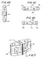
- the entire core 41 may be formed as an integral piece of magnetic material as shown in FIG. 3 or as two E-shaped magnetic sections as shown in FIG. 4A.
- FIG. 4A illustrates a variation of the core 41 employed in the invention shown in FIG. 3 above.
- the core 41 has three legs 42, 43 and 44 as in FIG. 3. Additionally, the core 41 includes connecting portions 48, 49, 50 and 51 between the three legs of the core.
- the core 41 is composed of two E-shaped sections of magnetic material 41a and 41b. The E-shaped sections of magnetic material 41a and 41b are clamped together such that their faces meet at boundary 52 to form the three-leg core.
- FIG. 4B is a cross-sectional view of the core 41 taken along line B-B in FIG. 4A.
- the cross-section of each leg 42, 43 and 44 is circular as shown in FIG. 4B.
- the cross-section of each leg 42, 43 and 44 is constant across the length of the leg as better seen in FIG. 4A.
- the cross-sectional area of center leg 43 is equal to or larger than the cross-sectional areas of the outer legs 42 and 44.
- the magnetic cross-section of the center leg 43 is equal to or somewhat larger than the sum of the magnetic cross-sections of the outer legs 42 and 44.
- the portions 50 and 51 of the core connecting the three legs 42, 43 and 44 are tapered down from the center leg 43 toward the outer legs 42 and 44. Accordingly, the cross-sectional areas of the connecting portions 50 and 51 (as well as similar connecting portions 48 and 49) vary along the length of the connecting portions, with the cross-sectional area of each connecting portion taken close to the center leg 43 being greater than the cross-sectional area of the same connecting portion taken close to one of the outer legs 42 and 44.
- FIG. 4C is a cross-sectional view of the core 41 illustrated in FIG. 4A taken along line C-C.
- a similar cross-sectional view would be obtained if taken along a symmetrical horizontal line through connecting portions 51 and 49 and looking toward leg 44. (Further, similar views could be obtained for the core 41 of FIG. 3 but these views do not have the boundaries 52.)
- leg 42 (as well as legs 43 and 44, not shown in FIG. 4C) has a constant cross-sectional area along the length of the leg 42.
- connecting portions 50 and 48 have circular cross-sectional areas. As shown in FIG.
- the circular cross-sectional areas of connecting portions 48 and 50 vary along the length of the connecting portions with the cross-sectional area of each of the connecting portions taken close to the outer-legs 42 and 44 being smaller than the cross-sectional area of each of the connecting portions taken close to the center leg 43.
- FIG. 4D is an alternate cross-sectional view of the core 41 illustrated in FIG.4A taken along line C-C showing rectangular cross-sections for the connecting portions 48 and 50. Other shapes may also be employed for the cross-sections of the connecting portions 48-51.
- the cross-sectional areas of the connecting portions 48-51 may vary in one or two dimensions along the length of the connecting portions, with the cross-sectional area of each connecting portion taken close to the center leg 43 being greater than the cross-sectional area of the same connecting portion when close to one of the outer legs 42 and 44.
- center leg 43 shown in FIG. 4A comprises a first part 43a which is part of section 41a of magnetic material and a second part 43b which is part of section 41 b of magnetic material
- center leg 43 is still considered a "single magnetic element" as defined herein.
- the language "a single magnetic element” is meant to designate a magnetic element (such as a leg of a core) with a continuous single piece of magnetic material throughout at least one cross-section cut perpendicular to the direction of the flow of flux ⁇ during operation.
- the magnet flux ⁇ flows along the length of the center leg 43 during operation.
- the cross-section taken perpendicular to the flow of flux ⁇ is not composed of multiple magnetic elements such as lamination strips or additional bodies added to increase the cross-section of the element.
- sections 41a and 41b of magnetic material illustrated by boundaries 52 does not increase the cross-sectional area of the center leg 43 and does not mean that center leg 43 is composed of more than a "single magnetic element", because the cross-section, cut perpendicular to the flow of flux ⁇ during operation, shows only a single magnetic element. The same magnetic material is employed throughout the cross-section.
- the control current Ic through center windings 45 causes the inductances L 46 and L 47 across the outer windings 46 and 47 to vary by changing the saturation levels of the outer legs 42 and 44.
- the inductance L 45 of the control winding 45 remains substantially constant with the change in the control current Ic through control winding 45.
- the control current Ic through winding 45 is large enough that the outer legs 42 and 44 of the core 41 saturate, which lowers the magnetic permeability of the core and results in a decrease in the inductances L 46 and L 47 of the parallel outer windings 46 and 47.
- the connecting portions 48-51 of the core 41 may be tapered to make sure that there is a minimum incremental increase or "step" in cross-sectional area from the legs to the connecting limbs. "Steps" in cross-sectional area will leave parts of the core material non-saturated around the "steps". This limits the minimum inductance and the variation range of the inductance.
- the tapered connecting portions permit a greater variation in the inductances L 46 and L 47 for a given control current Ic through control winding 45.
- a circular cross-section for the core 41 as opposed to another type of cross-section such as a rectangular cross-section, provides a more homogenous spread of the magnetic flux through the cross-section which results in a more homogenous saturation of the magnetic material of the legs and connecting portions.
- a greater variation in inductance for a given control winding current Ic may be obtained.
- a circle has the shortest possible perimeter for a given cross-section. Accordingly, a given number of turns around a circular leg of the core 41 will require a shorter total length of wire than that required for legs having a different cross-sectional area such as a rectangle. The shorter total length of wire results in lower power loss in the variable inductor 40.
- FIG. 5 is a perspective view of the invention shown in FIG. 3.
- the inductance of the control winding 45 will be substantially constant, if the magnetic cross-section of the center leg 43 is somewhat larger than the sum of the magnetic cross-sections of the outer legs 42 and 43 provided that the outer legs and the center leg have substantially equal levels of saturation.
- the inductance L 45 of the control winding 45 on the center leg 43 is of a low value in comparison to the inductances L 12 and L 13 in the prior art circuit of FIG. 1. Further, the inductance of control winding 45 does not change significantly with a change in control current Ic. In fact, as stated above, if the magnetic cross-section of the center leg 43 is exactly equal to the sum of the magnetic cross-sections of the outer legs 42 and 44, the inductance of control winding 45 will not change at all with the control current Ic. Outer windings 46 and 47 act as short circuited secondary windings on a transformer having winding 45 as the primary winding. Thus, the inductance L 45 of control winding 45 is only determined by the leakage inductance of the transformer. Accordingly, the inductance L 45 of the control winding 45 may be a low and substantially constant value.
- the invention further contemplates a method of varying the inductance L 46 or L 47 of an inductive circuit element 46 or 47 in accordance with a control current Ic.
- a three leg core of saturable magnetic material is obtained, the magnetic cross-section of a center leg 43 of the core 41, relative to magnetic cross-sections of two outer legs 42 and 44 of the core 41 set so that the outer legs 42 and 44 and the center legs 43 have substantially equal saturation levels when the control current is varied the parallel windings 46 and 47 are wound on the outer legs 42 and 44 of the three-leg core in such a way that the magnetic flux ⁇ arising from current through the parallel windings 46 and 47 is cancelled in the center leg 43 of the core.
- a control winding 45 is wound on the center leg 43 of the core.
- the control current Ic of the control winding 45 is varied to change the saturation level of the outer legs 42 and 44 of the core 41 to vary the inductance L 46 and L 47 of each of the parallel windings 46 and 47 on the outer legs 42 and 44.
- the inductance L 45 of the control winding 45 on the center leg 43 of the core is maintained substantially constant with changes in the current Ic on the control winding 45.
Landscapes
- Engineering & Computer Science (AREA)
- Power Engineering (AREA)
- Coils Or Transformers For Communication (AREA)
- Transformers For Measuring Instruments (AREA)
- Amplifiers (AREA)
- Transition And Organic Metals Composition Catalysts For Addition Polymerization (AREA)
- Compositions Of Oxide Ceramics (AREA)
- Control Of Electrical Variables (AREA)
Claims (7)
- Veränderlicher Induktor (40), der umfasst:einen Kern (41), der aus einem sättigungsfähigen magnetischen Material besteht, wobei der Kern drei Schenkel (42, 43, 44) hat, die einen mittleren Schenkel (43) und zwei äußere Schenkel (42, 44) enthalten;eine Steuerwicklung (45) auf dem mittleren Schenkel und Wicklungen (46, 47) auf jedem der äußeren Schenkel, die parallel so verbunden sind, dass der magnetische Fluss, der durch Ströme durch die Wicklungen auf den äußeren Schenkeln entsteht, in dem mittleren Schenkel aufgehoben wird;wobei ein Strom durch die Steuerwicklung eine geänderte Induktivität über die Wicklungen auf den äußeren Schenkeln verursacht, indem der Sättigungspegel der äußeren Schenkel geändert wird, der magnetische Querschnitt des mittleren Schenkels relativ zu den magnetischen Querschnitten der äußeren Schenkel so ist, dass die äußeren Schenkel und der mittlere Schenkel im Wesentlichen gleiche Sättigungspegel haben, und der magnetische Querschnitt des mittleren Schenkels genauso groß ist wie oder größer als die Summe der magnetischen Querschnitte der äußeren Schenkel, dadurch gekennzeichnet, dass die Induktivität der Steuerwicklung bei einer Änderung des Stroms in der Steuerwicklung im Wesentlichen konstant ist und der mittlere Schenkel ein einzelnes magnetisches Element umfasst.
- Veränderlicher Induktor nach Anspruch 1, wobei sich die Abschnitte des Kerns, die die drei Schenkel verbinden, von dem mittleren Schenkel zu den äußeren Schenkeln hin verjüngen.
- Veränderlicher Induktor nach Anspruch 1 oder 2, wobei der mittlere Schenkel durch ein einzelnes magnetisches Element gebildet wird.
- Veränderlicher Induktor nach einem der vorangehenden Ansprüche, wobei wenigstens einer der Schenkel des Kerns einen im Wesentlichen kreisförmigen Querschnitt hat,
- Veränderlicher Induktor nach einem der vorangehenden Ansprüche, wobei wenigstens einer der Abschnitte des Kerns, der die Schenkel verbindet, einen im Wesentlichen kreisförmigen Querschnitt hat.
- Veränderlicher Induktor nach einem der vorangehenden Ansprüche, wobei die Abschnitte des Kerns, die die Schenkel verbinden, sich in wenigstens einer Dimension verjüngen.
- Verfahren zum Verändern der Induktivität eines induktiven Schaltungselementes entsprechend einem Steuerstrom, das umfasst:a) Erzeugen eines Kerns (41) aus sättigungsfähigem magnetischem Material mit drei Schenkeln;b) Wickeln paralleler Wicklungen (46; 47) auf die äußeren Schenkel des Kerns so, dass der magnetische Fluss, der durch Strom durch die parallelen Wicklungen entsteht, in dem mittleren Schenkel des Kerns aufgehoben wird;c) Wickeln einer Steuerwicklung (45) auf den mittleren Schenkel des Kerns; undd) Verändern des Steuerstroms an der Steuerwicklung, um den Sättigungspegel der äußeren Schenkel des Kerns zu ändern und die Induktivität jeder der parallelen Wicklungen zu verändern;dadurch gekennzeichnet, dass die Induktivität der Steuerwicklung auf dem mittleren Schenkel des Kerns bei Änderungen des Stroms an der Steuerwicklung im Wesentlichen konstant bleibt und der mittlere Schenkel ein einzelnes magnetisches Element umfasst;
ein magnetischer Querschnitt eines mittleren Schenkels (43) des Kerns relativ zu magnetischen Querschnitten von zwei äußeren Schenkeln (42, 44) des Kerns so eingestellt ist, dass die äußeren Schenkel und der mittlere Schenkel im Wesentlichen gleiche Sättigungspegel haben und der magnetische Querschnitt des mittleren Schenkels genauso groß ist wie oder größer als die Summe der magnetischen Querschnitte der äußeren Schenkel.
Applications Claiming Priority (3)
| Application Number | Priority Date | Filing Date | Title |
|---|---|---|---|
| US80555 | 1998-05-18 | ||
| US09/080,555 US6317021B1 (en) | 1998-05-18 | 1998-05-18 | Variable inductor |
| PCT/US1999/010036 WO1999060585A1 (en) | 1998-05-18 | 1999-05-07 | Variable inductor |
Publications (3)
| Publication Number | Publication Date |
|---|---|
| EP1082735A1 EP1082735A1 (de) | 2001-03-14 |
| EP1082735A4 EP1082735A4 (de) | 2004-02-25 |
| EP1082735B1 true EP1082735B1 (de) | 2006-11-02 |
Family
ID=22158133
Family Applications (1)
| Application Number | Title | Priority Date | Filing Date |
|---|---|---|---|
| EP99921775A Expired - Lifetime EP1082735B1 (de) | 1998-05-18 | 1999-05-07 | Variable induktivität |
Country Status (10)
| Country | Link |
|---|---|
| US (1) | US6317021B1 (de) |
| EP (1) | EP1082735B1 (de) |
| JP (1) | JP2002516479A (de) |
| CN (2) | CN1301390A (de) |
| AT (1) | ATE344526T1 (de) |
| AU (1) | AU3889699A (de) |
| CA (1) | CA2329961A1 (de) |
| DE (1) | DE69933866T2 (de) |
| TW (1) | TW419681B (de) |
| WO (1) | WO1999060585A1 (de) |
Families Citing this family (53)
| Publication number | Priority date | Publication date | Assignee | Title |
|---|---|---|---|---|
| DE10260246B4 (de) * | 2002-12-20 | 2006-06-14 | Minebea Co., Ltd. | Spulenanordnung mit veränderbarer Induktivität |
| US7242275B2 (en) * | 2003-02-05 | 2007-07-10 | Paper Quality Management Associates | Variable inductor |
| DE10331866B4 (de) * | 2003-07-14 | 2008-11-13 | Minebea Co., Ltd. | Einrichtung zur Steuerung einer Spulenanordnung mit elektrisch variierbarer Induktivität, sowie Schaltnetzteil |
| CN100341240C (zh) * | 2005-05-31 | 2007-10-03 | 珠海市东华金舟节能设备有限公司 | 交流励磁磁放大器的可控电感 |
| US9197132B2 (en) | 2006-12-01 | 2015-11-24 | Flextronics International Usa, Inc. | Power converter with an adaptive controller and method of operating the same |
| US7675759B2 (en) | 2006-12-01 | 2010-03-09 | Flextronics International Usa, Inc. | Power system with power converters having an adaptive controller |
| US7468649B2 (en) * | 2007-03-14 | 2008-12-23 | Flextronics International Usa, Inc. | Isolated power converter |
| JP5102872B2 (ja) * | 2007-04-17 | 2012-12-19 | イノパワー スーパーコンダクター ケーブル カンパニー リミテッド | 飽和鉄心式超伝導故障限流器および該故障限流器の制御方法 |
| DE102008064640A1 (de) * | 2008-05-21 | 2009-12-03 | Sew-Eurodrive Gmbh & Co. Kg | Induktivität und Anordnung |
| WO2010056989A1 (en) | 2008-11-14 | 2010-05-20 | Flextronics International Usa, Inc. | Driver for a synchronous rectifier and power converter employing the same |
| US8520414B2 (en) | 2009-01-19 | 2013-08-27 | Power Systems Technologies, Ltd. | Controller for a power converter |
| WO2010083514A1 (en) * | 2009-01-19 | 2010-07-22 | Flextronics International Usa, Inc. | Controller for a power converter |
| WO2010114914A1 (en) | 2009-03-31 | 2010-10-07 | Flextronics International Usa, Inc. | Magnetic device formed with u-shaped core pieces and power converter employing the same |
| US8643222B2 (en) * | 2009-06-17 | 2014-02-04 | Power Systems Technologies Ltd | Power adapter employing a power reducer |
| US9077248B2 (en) | 2009-06-17 | 2015-07-07 | Power Systems Technologies Ltd | Start-up circuit for a power adapter |
| US8514593B2 (en) | 2009-06-17 | 2013-08-20 | Power Systems Technologies, Ltd. | Power converter employing a variable switching frequency and a magnetic device with a non-uniform gap |
| US8638578B2 (en) | 2009-08-14 | 2014-01-28 | Power System Technologies, Ltd. | Power converter including a charge pump employable in a power adapter |
| CN102349120B (zh) * | 2009-09-03 | 2013-10-09 | 松下电器产业株式会社 | 线圈部件及其制造方法 |
| CN101661826A (zh) * | 2009-09-10 | 2010-03-03 | 刘有斌 | 直流偏磁式可控电抗器 |
| US8976549B2 (en) | 2009-12-03 | 2015-03-10 | Power Systems Technologies, Ltd. | Startup circuit including first and second Schmitt triggers and power converter employing the same |
| US8520420B2 (en) | 2009-12-18 | 2013-08-27 | Power Systems Technologies, Ltd. | Controller for modifying dead time between switches in a power converter |
| US9246391B2 (en) | 2010-01-22 | 2016-01-26 | Power Systems Technologies Ltd. | Controller for providing a corrected signal to a sensed peak current through a circuit element of a power converter |
| US8787043B2 (en) | 2010-01-22 | 2014-07-22 | Power Systems Technologies, Ltd. | Controller for a power converter and method of operating the same |
| CN102870320B (zh) | 2010-03-17 | 2016-11-02 | 电力系统技术有限公司 | 功率转换器的控制系统及其操作方法 |
| KR20120020325A (ko) * | 2010-08-30 | 2012-03-08 | 삼성전자주식회사 | 역률 개선 회로용 인덕터 코어 |
| US20120139678A1 (en) * | 2010-12-03 | 2012-06-07 | Abb Technology Ag | Non-Linear Transformer with Improved Construction and Method of Manufacturing the Same |
| CN102208245B (zh) * | 2011-02-24 | 2013-02-20 | 中国科学院电工研究所 | 一种磁饱和式单相可控电抗器 |
| CN102208247B (zh) * | 2011-02-24 | 2012-12-12 | 中国科学院电工研究所 | 高压磁饱和式单相可控电抗器 |
| CN102208244B (zh) * | 2011-02-24 | 2012-12-12 | 中国科学院电工研究所 | 一种正交磁化的单相可控电抗器 |
| CN102208246B (zh) * | 2011-02-24 | 2013-02-20 | 中国科学院电工研究所 | 高压正交磁化的单相可控电抗器 |
| US8792257B2 (en) | 2011-03-25 | 2014-07-29 | Power Systems Technologies, Ltd. | Power converter with reduced power dissipation |
| CA2858450A1 (en) * | 2011-12-09 | 2013-06-13 | Francis Anthony Darmann | Fault current limiter |
| CN102573163B (zh) * | 2012-01-18 | 2013-08-21 | 桂林电子科技大学 | 电子束熔炼炉高压电源装置 |
| US8792256B2 (en) | 2012-01-27 | 2014-07-29 | Power Systems Technologies Ltd. | Controller for a switch and method of operating the same |
| US9190898B2 (en) | 2012-07-06 | 2015-11-17 | Power Systems Technologies, Ltd | Controller for a power converter and method of operating the same |
| US9214264B2 (en) | 2012-07-16 | 2015-12-15 | Power Systems Technologies, Ltd. | Magnetic device and power converter employing the same |
| US9099232B2 (en) | 2012-07-16 | 2015-08-04 | Power Systems Technologies Ltd. | Magnetic device and power converter employing the same |
| US9379629B2 (en) | 2012-07-16 | 2016-06-28 | Power Systems Technologies, Ltd. | Magnetic device and power converter employing the same |
| US9106130B2 (en) | 2012-07-16 | 2015-08-11 | Power Systems Technologies, Inc. | Magnetic device and power converter employing the same |
| US9240712B2 (en) | 2012-12-13 | 2016-01-19 | Power Systems Technologies Ltd. | Controller including a common current-sense device for power switches of a power converter |
| RU2576630C2 (ru) * | 2013-05-08 | 2016-03-10 | Федеральное государственное бюджетное учреждение науки Институт систем энергетики им. Л.А. Мелентьева Сибирского отделения Российской академии наук (ИСЭМ СО РАН) | Управляемый подмагничиванием трансформатор |
| US9300206B2 (en) | 2013-11-15 | 2016-03-29 | Power Systems Technologies Ltd. | Method for estimating power of a power converter |
| KR102195785B1 (ko) * | 2013-12-20 | 2020-12-28 | 토쿠덴 가부시기가이샤 | 전원 회로, 스콧 결선 변압기용 철심, 스콧 결선 변압기 및 과열 수증기 생성 장치 |
| US10910150B2 (en) * | 2015-11-30 | 2021-02-02 | Intel Corporation | Reconfigurable coupled inductor |
| US10193534B2 (en) * | 2015-12-17 | 2019-01-29 | Garrity Power Services Llc | Wireless power system tuning apparatus |
| US9905354B2 (en) * | 2015-12-18 | 2018-02-27 | Cisco Technology, Inc. | Electrical device with integrated transformer and common mode choke |
| US10438739B2 (en) * | 2016-05-04 | 2019-10-08 | Toyota Motor Engineering & Manufacturing North America, Inc. | Transformer with integrated leakage inductance |
| US10504645B2 (en) * | 2016-05-05 | 2019-12-10 | Ut-Battelle, Llc | Gapless core reactor |
| WO2018075748A1 (en) * | 2016-10-19 | 2018-04-26 | University Of Florida Research Foundation, Incorporated | Multi-phase coupled inductor having compensation windings |
| CN108735449A (zh) * | 2017-04-25 | 2018-11-02 | 台达电子工业股份有限公司 | 磁性组件、电感及变压器 |
| CN108682541A (zh) * | 2018-04-26 | 2018-10-19 | 西南交通大学 | 一种牵引变压器 |
| CN109217277B (zh) * | 2018-10-23 | 2020-03-17 | 西安交通大学 | 一种用于提升换流阀可靠性的换相过电压抑制器 |
| CN111342668B (zh) * | 2020-03-09 | 2021-07-06 | 西南交通大学 | 一种利用可变电感拓展ss结构wpt系统的软开关范围的方法 |
Family Cites Families (14)
| Publication number | Priority date | Publication date | Assignee | Title |
|---|---|---|---|---|
| US390245A (en) * | 1888-10-02 | Electric-arc lamp | ||
| DE356227C (de) * | 1919-09-05 | 1922-07-18 | Siemens Schuckertwerke G M B H | Hochspannungstransformator oder Drosselspule mit unbeweglichem Eisenkoerper ohne magnetischen Nebenschluss |
| US2169093A (en) | 1937-01-02 | 1939-08-08 | Gen Electric | Electrical control system |
| US2317602A (en) | 1941-09-19 | 1943-04-27 | Alfred P Daniels | Lamp starter and maintenance device |
| US2552203A (en) | 1948-04-02 | 1951-05-08 | Gen Electric | Voltage doubler magnetic amplifier |
| US2550500A (en) * | 1948-09-24 | 1951-04-24 | Gen Electric | Low yoke transformer core |
| GB715610A (en) | 1950-09-20 | 1954-09-15 | Gen Electric Co Ltd | Improvements in or relating to variable inductive elements having saturable cores |
| US2896182A (en) * | 1955-09-17 | 1959-07-21 | Pruneau Pierre Marie | Magnetic circuits for stationary electrical induction apparatus |
| US2991437A (en) * | 1955-09-20 | 1961-07-04 | Elin Ag Fur Elek Sche Ind | Magnetic core |
| US2932787A (en) | 1956-03-19 | 1960-04-12 | Allis Chalmers Mfg Co | Magnetic amplifier |
| US3631534A (en) | 1969-09-05 | 1971-12-28 | Matsushita Electric Ind Co Ltd | Variable inductance device |
| US3708775A (en) * | 1971-08-06 | 1973-01-02 | Esb Inc | Adjustable impedance regulating transformer |
| US5426409A (en) | 1994-05-24 | 1995-06-20 | The United States Of America As Represented By The Secretary Of The Navy | Current controlled variable inductor |
| JPH09129450A (ja) * | 1995-10-26 | 1997-05-16 | Nagano Japan Radio Co | 誘導性素子 |
-
1998
- 1998-05-18 US US09/080,555 patent/US6317021B1/en not_active Expired - Fee Related
-
1999
- 1999-05-07 AU AU38896/99A patent/AU3889699A/en not_active Abandoned
- 1999-05-07 DE DE69933866T patent/DE69933866T2/de not_active Expired - Fee Related
- 1999-05-07 JP JP2000550114A patent/JP2002516479A/ja not_active Withdrawn
- 1999-05-07 AT AT99921775T patent/ATE344526T1/de not_active IP Right Cessation
- 1999-05-07 CN CN99806328.2A patent/CN1301390A/zh active Pending
- 1999-05-07 WO PCT/US1999/010036 patent/WO1999060585A1/en active IP Right Grant
- 1999-05-07 EP EP99921775A patent/EP1082735B1/de not_active Expired - Lifetime
- 1999-05-07 CA CA002329961A patent/CA2329961A1/en not_active Abandoned
- 1999-05-13 TW TW088107800A patent/TW419681B/zh not_active IP Right Cessation
-
2002
- 2002-01-17 CN CN02101875.8A patent/CN1379419A/zh active Pending
Also Published As
| Publication number | Publication date |
|---|---|
| CN1301390A (zh) | 2001-06-27 |
| EP1082735A4 (de) | 2004-02-25 |
| CN1379419A (zh) | 2002-11-13 |
| US6317021B1 (en) | 2001-11-13 |
| EP1082735A1 (de) | 2001-03-14 |
| ATE344526T1 (de) | 2006-11-15 |
| TW419681B (en) | 2001-01-21 |
| DE69933866D1 (de) | 2006-12-14 |
| DE69933866T2 (de) | 2007-06-28 |
| AU3889699A (en) | 1999-12-06 |
| JP2002516479A (ja) | 2002-06-04 |
| WO1999060585A1 (en) | 1999-11-25 |
| CA2329961A1 (en) | 1999-11-25 |
Similar Documents
| Publication | Publication Date | Title |
|---|---|---|
| EP1082735B1 (de) | Variable induktivität | |
| US5155676A (en) | Gapped/ungapped magnetic core | |
| US4009460A (en) | Inductor | |
| US5619400A (en) | Magnetic core structures and construction techniques therefor | |
| US3659191A (en) | Regulating transformer with non-saturating input and output regions | |
| US5747981A (en) | Inductor for an electrical system | |
| US20080192960A1 (en) | Hybrid Filter for Audio Switching Amplifier | |
| US7161458B2 (en) | Electromagnetic device having independent inductive components | |
| JPH04355906A (ja) | チョ―クコイル及びスイッチング電源装置のノイズ低減装置 | |
| EP3471250A1 (de) | Spannungsumwandlungsvorrichtung und leckageinduktanzbestimmungsverfahren | |
| US5506559A (en) | Choke coil for eliminating common mode noise and normal mode noise | |
| US7439843B2 (en) | Transformers | |
| US6198644B1 (en) | Rectifying/smoothing circuit and double-ended converter | |
| Witulski | Modeling and design of transformers and coupled inductors | |
| JPH03215911A (ja) | 可変インダクタ | |
| JPH0644539B2 (ja) | 内鉄形変圧器 | |
| CN115210830A (zh) | 具有电气可变特性的磁性部件 | |
| DE3423160C2 (de) | Steuerbare, Spannung wandelnde elektrische Maschine | |
| CA1181495A (en) | Ferro-resonant-type transformer | |
| US5886507A (en) | Controlled ferroresonant transformer | |
| JP2580367Y2 (ja) | ノイズフィルタ用チョークコイル | |
| JPH0316205A (ja) | 可変インダクタ | |
| JPS6111457B2 (de) | ||
| CN116417224A (zh) | 铁芯结构及电压变换器 | |
| CN115831558A (zh) | 耦合电感器 |
Legal Events
| Date | Code | Title | Description |
|---|---|---|---|
| PUAI | Public reference made under article 153(3) epc to a published international application that has entered the european phase |
Free format text: ORIGINAL CODE: 0009012 |
|
| 17P | Request for examination filed |
Effective date: 20001128 |
|
| AK | Designated contracting states |
Kind code of ref document: A1 Designated state(s): AT BE CH DE DK FR GB IE IT LI NL SE |
|
| RAP1 | Party data changed (applicant data changed or rights of an application transferred) |
Owner name: MINEBEA CO., LTD |
|
| A4 | Supplementary search report drawn up and despatched |
Effective date: 20040113 |
|
| RIC1 | Information provided on ipc code assigned before grant |
Ipc: 7H 01F 27/24 B Ipc: 7H 01F 29/14 A |
|
| 17Q | First examination report despatched |
Effective date: 20040615 |
|
| GRAP | Despatch of communication of intention to grant a patent |
Free format text: ORIGINAL CODE: EPIDOSNIGR1 |
|
| GRAS | Grant fee paid |
Free format text: ORIGINAL CODE: EPIDOSNIGR3 |
|
| GRAA | (expected) grant |
Free format text: ORIGINAL CODE: 0009210 |
|
| AK | Designated contracting states |
Kind code of ref document: B1 Designated state(s): AT BE CH DE DK FR GB IE IT LI NL SE |
|
| PG25 | Lapsed in a contracting state [announced via postgrant information from national office to epo] |
Ref country code: NL Free format text: LAPSE BECAUSE OF FAILURE TO SUBMIT A TRANSLATION OF THE DESCRIPTION OR TO PAY THE FEE WITHIN THE PRESCRIBED TIME-LIMIT Effective date: 20061102 Ref country code: LI Free format text: LAPSE BECAUSE OF FAILURE TO SUBMIT A TRANSLATION OF THE DESCRIPTION OR TO PAY THE FEE WITHIN THE PRESCRIBED TIME-LIMIT Effective date: 20061102 Ref country code: IT Free format text: LAPSE BECAUSE OF FAILURE TO SUBMIT A TRANSLATION OF THE DESCRIPTION OR TO PAY THE FEE WITHIN THE PRESCRIBED TIME-LIMIT;WARNING: LAPSES OF ITALIAN PATENTS WITH EFFECTIVE DATE BEFORE 2007 MAY HAVE OCCURRED AT ANY TIME BEFORE 2007. THE CORRECT EFFECTIVE DATE MAY BE DIFFERENT FROM THE ONE RECORDED. Effective date: 20061102 Ref country code: CH Free format text: LAPSE BECAUSE OF FAILURE TO SUBMIT A TRANSLATION OF THE DESCRIPTION OR TO PAY THE FEE WITHIN THE PRESCRIBED TIME-LIMIT Effective date: 20061102 Ref country code: BE Free format text: LAPSE BECAUSE OF FAILURE TO SUBMIT A TRANSLATION OF THE DESCRIPTION OR TO PAY THE FEE WITHIN THE PRESCRIBED TIME-LIMIT Effective date: 20061102 Ref country code: AT Free format text: LAPSE BECAUSE OF FAILURE TO SUBMIT A TRANSLATION OF THE DESCRIPTION OR TO PAY THE FEE WITHIN THE PRESCRIBED TIME-LIMIT Effective date: 20061102 |
|
| REG | Reference to a national code |
Ref country code: GB Ref legal event code: FG4D |
|
| REG | Reference to a national code |
Ref country code: IE Ref legal event code: FG4D |
|
| REG | Reference to a national code |
Ref country code: CH Ref legal event code: EP |
|
| REF | Corresponds to: |
Ref document number: 69933866 Country of ref document: DE Date of ref document: 20061214 Kind code of ref document: P |
|
| PG25 | Lapsed in a contracting state [announced via postgrant information from national office to epo] |
Ref country code: SE Free format text: LAPSE BECAUSE OF FAILURE TO SUBMIT A TRANSLATION OF THE DESCRIPTION OR TO PAY THE FEE WITHIN THE PRESCRIBED TIME-LIMIT Effective date: 20070202 Ref country code: DK Free format text: LAPSE BECAUSE OF FAILURE TO SUBMIT A TRANSLATION OF THE DESCRIPTION OR TO PAY THE FEE WITHIN THE PRESCRIBED TIME-LIMIT Effective date: 20070202 |
|
| NLV1 | Nl: lapsed or annulled due to failure to fulfill the requirements of art. 29p and 29m of the patents act | ||
| REG | Reference to a national code |
Ref country code: CH Ref legal event code: PL |
|
| EN | Fr: translation not filed | ||
| PLBE | No opposition filed within time limit |
Free format text: ORIGINAL CODE: 0009261 |
|
| STAA | Information on the status of an ep patent application or granted ep patent |
Free format text: STATUS: NO OPPOSITION FILED WITHIN TIME LIMIT |
|
| 26N | No opposition filed |
Effective date: 20070803 |
|
| PGFP | Annual fee paid to national office [announced via postgrant information from national office to epo] |
Ref country code: GB Payment date: 20070530 Year of fee payment: 9 |
|
| PG25 | Lapsed in a contracting state [announced via postgrant information from national office to epo] |
Ref country code: FR Free format text: LAPSE BECAUSE OF FAILURE TO SUBMIT A TRANSLATION OF THE DESCRIPTION OR TO PAY THE FEE WITHIN THE PRESCRIBED TIME-LIMIT Effective date: 20070615 |
|
| PG25 | Lapsed in a contracting state [announced via postgrant information from national office to epo] |
Ref country code: IE Free format text: LAPSE BECAUSE OF NON-PAYMENT OF DUE FEES Effective date: 20070508 |
|
| PGFP | Annual fee paid to national office [announced via postgrant information from national office to epo] |
Ref country code: DE Payment date: 20080530 Year of fee payment: 10 |
|
| PG25 | Lapsed in a contracting state [announced via postgrant information from national office to epo] |
Ref country code: FR Free format text: LAPSE BECAUSE OF FAILURE TO SUBMIT A TRANSLATION OF THE DESCRIPTION OR TO PAY THE FEE WITHIN THE PRESCRIBED TIME-LIMIT Effective date: 20061102 |
|
| GBPC | Gb: european patent ceased through non-payment of renewal fee |
Effective date: 20080507 |
|
| PG25 | Lapsed in a contracting state [announced via postgrant information from national office to epo] |
Ref country code: GB Free format text: LAPSE BECAUSE OF NON-PAYMENT OF DUE FEES Effective date: 20080507 |
|
| PG25 | Lapsed in a contracting state [announced via postgrant information from national office to epo] |
Ref country code: DE Free format text: LAPSE BECAUSE OF NON-PAYMENT OF DUE FEES Effective date: 20091201 |