EP1081759A2 - Cooling unit - Google Patents
Cooling unit Download PDFInfo
- Publication number
- EP1081759A2 EP1081759A2 EP00303110A EP00303110A EP1081759A2 EP 1081759 A2 EP1081759 A2 EP 1081759A2 EP 00303110 A EP00303110 A EP 00303110A EP 00303110 A EP00303110 A EP 00303110A EP 1081759 A2 EP1081759 A2 EP 1081759A2
- Authority
- EP
- European Patent Office
- Prior art keywords
- heat
- cooling unit
- liquid coolant
- radiator
- hollow tube
- Prior art date
- Legal status (The legal status is an assumption and is not a legal conclusion. Google has not performed a legal analysis and makes no representation as to the accuracy of the status listed.)
- Withdrawn
Links
Images







Classifications
-
- H—ELECTRICITY
- H10—SEMICONDUCTOR DEVICES; ELECTRIC SOLID-STATE DEVICES NOT OTHERWISE PROVIDED FOR
- H10W—GENERIC PACKAGES, INTERCONNECTIONS, CONNECTORS OR OTHER CONSTRUCTIONAL DETAILS OF DEVICES COVERED BY CLASS H10
- H10W40/00—Arrangements for thermal protection or thermal control
- H10W40/70—Fillings or auxiliary members in containers or in encapsulations for thermal protection or control
- H10W40/73—Fillings or auxiliary members in containers or in encapsulations for thermal protection or control for cooling by change of state
-
- F—MECHANICAL ENGINEERING; LIGHTING; HEATING; WEAPONS; BLASTING
- F28—HEAT EXCHANGE IN GENERAL
- F28D—HEAT-EXCHANGE APPARATUS, NOT PROVIDED FOR IN ANOTHER SUBCLASS, IN WHICH THE HEAT-EXCHANGE MEDIA DO NOT COME INTO DIRECT CONTACT
- F28D15/00—Heat-exchange apparatus with the intermediate heat-transfer medium in closed tubes passing into or through the conduit walls ; Heat-exchange apparatus employing intermediate heat-transfer medium or bodies
- F28D15/02—Heat-exchange apparatus with the intermediate heat-transfer medium in closed tubes passing into or through the conduit walls ; Heat-exchange apparatus employing intermediate heat-transfer medium or bodies in which the medium condenses and evaporates, e.g. heat pipes
- F28D15/0266—Heat-exchange apparatus with the intermediate heat-transfer medium in closed tubes passing into or through the conduit walls ; Heat-exchange apparatus employing intermediate heat-transfer medium or bodies in which the medium condenses and evaporates, e.g. heat pipes with separate evaporating and condensing chambers connected by at least one conduit; Loop-type heat pipes; with multiple or common evaporating or condensing chambers
Definitions
- the present invention relates generally to a cooling unit, and more particularly, to a cooling unit to be used with semiconductor elements and other such heat-generating components.
- FIG. 1A is a diagram showing a conventional forced-air type cooling unit 100.
- FIG. 1B is a diagram showing a conventional forced-liquid type cooling unit 200.
- the air-cooled cooling unit 100 has a heat sink 103 made from material having a high rate of heat transmission such as aluminum or copper is provided on a heated part 101.
- the heat sink 103 is provided with a multiplicity of fins in order to increase the radiative effect.
- a flow of air forcibly created by a fan 105 cools these fins and so cools the heated part 101.
- the liquid-cooled cooling unit 200 has thermally conductive cold plates 203 provided in direct contact with the heated part 201. These cold plates 203 are positioned so as to contact a pipe 204 through which a liquid coolant 209 circulates opposite the heated part 201. When the liquid coolant 209 passes through the heat exchanger 207 it is heat exchanged and cooled, so the cold plates 203 can also be cooled and, accordingly, the heated part 201 is also cooled.
- This liquid-cooled cooling unit 200 has a pump 205 and a heat exchanger 207 having a fan 208 to forcibly cool the heated part 201.
- the above-described air-cooled cooling unit 100 uses air to cool the heated member 101, so the rate of heat transmission is very low and the radiative effect is poor. Moreover, the above-described cooling unit 100 uses an electrically driven fan 105 and thus requires power, in addition to which the fan generates noise and is subject to breakdowns.
- the liquid-cooled cooling unit 200 described above although it has good thermal conductivity, nevertheless still uses a pump 205 and a fan 208 and so is subject to the same disadvantages as those pertaining to the air-cooled cooling unit 100 described above, namely fan noise and fan breakdowns. Additionally, in the case of the liquid-cooled cooling unit 200 the pump or other equivalent circulatory device requires a great deal of space and must be maintained and serviced as well, which takes time and costs money.
- Another and more specific object of the present invention is to provide and improved and useful cooling unit which does not use an external power source and hence is quiet, economical, efficient and capable of effectively cooling heated parts.
- a cooling unit comprising:
- the circulation path of the liquid coolant is formed by the motive force created by the elevating force of the air bubbles, so the liquid coolant can be circulated without the use of an external drive source, thus making it possible to transfer the heat of the heat-receiving part to the radiator via the liquid coolant at reduced cost and no noise.
- the heat of the heat-receiving part is absorbed as the heat of evaporation when the liquid coolant is turned into a gas and the heat of aggregation is released when the air bubbles that reach the radiator are condensed and returned to a liquid state, so heat can be transferred more efficiently from the heat receiving part to the radiator and a cooling unit of high cooling effectiveness and efficiency can be provided.
- FIGS. 2A and 2B are diagrams showing plan and side views, respectively, of a cooling unit 10 according to a first embodiment of the present invention.
- the cooling unit 10 comprises a heat-receiving part 11, a radiator 13 and a U-shaped central hollow tube 15.
- the heat-receiving part 11 is positioned so as to contact a heat-emitting body 16 such as the CPU, and is made of a metal having high thermal conduction so as to take the heat from the heat-emitting body 16.
- the heat-receiving part 11 is further positioned in such a way that a curved portion of the U-shaped central hollow tube 15 for transporting a liquid coolant 17 to be described later is wrapped around the heat-emitting body 16.
- the radiator 13 is positioned at a distance from the heat-receiving part 11 and is provided with a mechanism for radiating recovered heat.
- the radiator 13 includes an interior space that forms a part of the circulation path through with the liquid coolant 17 circulates, and further includes an air pocket 14 for recovering air bubbles when these are present in the liquid coolant 17. Additionally, a radiating member 19 having a large radiating surface area for rapidly dissipating recovered heat is fixedly mounted on the radiator 13.
- the hollow tube 15 is disposed in a U-shaped manner so that the above-described liquid coolant 17 can circulate between the heat-receiving part 11 and the radiator 13. It should be noted that both end portions 15A, 15B of the tube 15 are connected to the radiator 13, so that by filling the radiator 13 with liquid coolant 17 the liquid coolant 17 can circulate.
- the tube 15 itself can be made of teflon, polyurethane, nylon or some other flexible material which when formed into a hollow tube can still be used when bent. Additionally, it is preferable that the tube 15 have a circular or oval cross-section, and, further, that the tube 15 have an inner diameter of between 1 mm and 50 mm, preferably between 2 mm and 25 mm.
- liquid coolant 17 a liquid capable of boiling at a lower temperature be selected for the liquid coolant 17, such as, for example, fluorine, which has a boiling point of 56oC and which is manufactured by 3M Corp. and marketed under the brand name Fluorinate.
- fluorine which has a boiling point of 56oC and which is manufactured by 3M Corp. and marketed under the brand name Fluorinate.
- the cooling unit 10 does not have a pump or other such external drive source for circulating the liquid coolant 17.
- a description will now be given of the mechanism by which the cooling unit 10 circulates the liquid coolant 17.
- the heat-receiving part 11 receives heat from the heat-emitting member 16 and become hot.
- the curved portion 15C of the tube 15 that contacts the heat-receiving part 11 also becomes hot, with the liquid coolant 17 present inside the tube 15 boiling when a predetermined temperature is reached, producing bubbles of air 17A.
- the air bubbles 17A rise toward the radiator 13 via that part of the tube 15 posing the least resistance, the tube 15 extending laterally to the left and right of the curved portion 15C through the heat-emitting member 16 (on the left side in FIG 2A).
- the rise of the air bubbles 17A produces an elevating force, on the basis of which an upward current X of the liquid coolant 17 arises.
- a downward current Y of the liquid coolant 17 is created inside the tube 15 on the side away from the side on which the upward current X arises (on the right side in FIG. 2A).
- a circulating current of liquid coolant 17 is formed, the direction of which is determined by the driving force caused by the elevating force of the air bubbles 17A.
- the present cooling unit 10 is thus able to circulate the liquid coolant 17 without using an external power source to do so. Accordingly, the heat arising at the heat-receiving part 11 from the heat-emitting member 16 is transported to the radiator 13 via the liquid coolant 17 where the heat is efficiently dissipated because the radiator 13 is provided with a radiating member 19.
- liquid coolant 17 air bubbles 17A are generated by absorbing the heat at the heat-receiving part 11, the liquid coolant 17 is driven upward by the elevating force of the rising air bubbles 17A, the liquid coolant 17 is then cooled at the radiator 13 and drops once more toward the heat-receiving part 11, where the process is repeated again from the beginning.
- the air bubbles 17A do not only act as a motive force impelling the circulation of the liquid coolant 17 as described above.
- the liquid coolant 17 changes from a liquid state to a gas, more heat is absorbed (latent heat absorption) from the heat-receiving part 11 as evaporative heat than is the case when the coolant is in a liquid state and transported to the radiator 13.
- the air bubbles 17A are gathered by the air pocket 14 of the radiator 13 but are here cooled and condense from a gaseous state back to a liquid state. At this time heat of aggregation is generated, in a development that is the converse of when the liquid coolant 17 is converted into a gas. Accordingly, the air bubbles 17A also perform the function of transporting the heat from the heat-receiving part 11 to the radiator 13 more efficiently.
- the cooling unit 10 it is important to make certain that the air bubbles 17A are generated.
- the air bubbles 17A be of a size that contacts the inner walls of the hollow tube 15 as the air bubbles 17A rise within the hollow tube 15, because such a size makes the circulation of the liquid coolant 17, which is thus alternately in a liquid state and a gaseous state, proceed more smoothly.
- the present cooling unit 10 uses air bubbles 17A to circulate the liquid coolant 17, so in order to use the cooling unit 10 the radiator 13 must be positioned at a height higher than a height of the heat-receiving part 11.
- the heat-receiving part 11 and the radiator 13 be positioned directly vertically one above the other but may instead be positioned at any angle at which the air bubbles 17A can securely rise upward. Additionally, there is no need to maintain the relative positions of the heat-receiving part 11 and the radiator 13 when the cooling unit 10 is not in use.
- the cooling unit 10 described above is best suited for cooling such heat-generating elements as the CPU inside laptop or notebook-type personal computers, in which the display screen is flipped open in order to use the device.
- the cooling unit 10 described above uses air bubbles 17A to form a circulating flow of liquid coolant 17 as noted previously, there is no need for an external drive source and hence the cooling unit is economical and quiet. Additionally, because the cooling unit 17 described above also utilizes the heat of evaporation, the transfer of heat from the heat-receiving part 11 to the radiator 13 can be carried out efficiently. Accordingly, the heat-emitting member 16 can be cooled efficiently.
- FIGS. 3A and 3B are diagrams showing plan and side views, respectively, of a cooling unit 20 according to a second embodiment of the present invention. As shown in the diagrams, the cooling unit 20 according to the second embodiment of the present invention has essentially the same structure as the cooling unit 10 according to the first embodiment of the present invention described above.
- the cooling unit 20 comprises a heat-receiving part 11, a radiator 13 and a hollow tube 22.
- the hollow tube 22 has a bent portion 22C inside the heat-receiving part 11, with the hollow tube 22 having an enlarged contact surface area contacting an inner surface of the heat-receiving part 11. Accordingly, the heat absorbed by the liquid coolant 17 that circulates inside the hollow tube 22 increases, so the cooling effect can be increased.
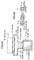
- FIGS. 4A and 4B are diagrams showing plan and side views, respectively, of a cooling unit 30 according to a third embodiment of the present invention.
- the cooling unit 30 according to a third embodiment of the present invention has essentially the same structure as the cooling unit 10 according to the first embodiment of the present invention described above.
- a heat-receiving part 31 includes a heat sink 32 capable of containing a specified volume of liquid coolant 17.
- a heat-emitting member 16 contacts a back portion of the heat sink 32.
- the capacity of the heat sink 32 to contain liquid coolant 17 is enlarged so that more of the heat generated by the heat-emitting member 16 is transferred more quickly by the liquid coolant 17.
- the heat sink 32 is formed from a thermally conductive material in the shape of a box inside the heat-receiving part 31. Accordingly, the liquid coolant 17 and the member that forms the heat-receiving part 31 directly contact each other without the intervention of a hollow tube, so the thermal resistance decreases and the amount of heat absorbed by the liquid coolant 17 increases.
- the heat sink 32 of the cooling unit 30 is connected to the radiator 13 via two hollow tubes 35A, 35B.
- the heat sink 32 also forms one part of the circulation path of the liquid coolant 17 together with the radiator 13 and the hollow tubes 35A, 35B.
- the liquid coolant 17 inside the heat sink 32 absorb heats, becomes hot, boils and thus generates air bubbles 17A which rise toward the radiator 13 via whichever of the hollow tubes 35A, 35B offers the least internal resistance (in the embodiment shown in FIG. 4A, the left side, that is, hollow tube 35B).
- an upwardly rising current X of liquid coolant 17 is generated using an elevating force of the air bubbles 17A as a source of motive power.
- a downwardly falling current Y of liquid coolant 17 is generated inside the other hollow tube 35A through which the air bubbles 17A do not rise, thus completing the circulation path of the liquid coolant 17.
- the cooling unit 30 according to the third embodiment also uses air bubbles 17A to form a circulating flow of liquid coolant 17 as noted previously, so there is no need for an external drive source and hence the cooling unit is economical and quiet. Additionally, because the cooling unit 17 described above also utilizes the heat of evaporation, the transfer of heat from the heat-receiving part 11 to the radiator 13 can be carried out efficiently. Accordingly, the heat-emitting member 16 can be cooled efficiently.
- FIG. 5 is a diagram showing a plan view of a cooling unit according to a fourth embodiment of the present invention.
- the cooling unit 40 according to the fourth embodiment of the present invention has essentially the same structure as the cooling unit 10 according to the first embodiment of the present invention described above.
- two hollow tubes 45A, 45B connect a heat sink 32 to a radiator 13.
- a diameter of the hollow tube 45B is larger than a diameter of the hollow tube 45A.
- FIG. 6 is a diagram of a plan view of a cooling unit according to a fifth embodiment of the present invention.
- the cooling unit 50 according to the fifth embodiment of the present invention has essentially the same structure as the cooling unit 30 according to the third embodiment of the present invention described above, being a variation of same insofar as the two hollow tubes are of different lengths.
- a heat sink 32 of the cooling unit 50 is connected to a radiator 13 by two hollow tubes 55A, 55B, with hollow tube 55B having a length shorter than that of hollow tube 55A.
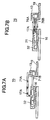
- FIG. 7A is a diagram showing a side view of a cooling unit 70 according to a sixth embodiment of the present invention
- FIG. 7B is a diagram showing a side view of another cooling unit 75 according to a sixth embodiment of the present invention.
- the cooling units 70 and 75 according to a sixth embodiment of the present invention have essentially the same structure as the cooling unit 30 according to a third embodiment of the present invention described above, being two variations of same insofar as the heights of the two hollow tubes 15 differ at time of usage.
- a heat sink 32 is connected to a radiator 13 by two hollow tubes 71A, 71B.
- Hollow tube 71A is extended from a side surface of the heat sink 32 so as to be positioned at a height higher than that of hollow tube 71B and is connected to the radiator 13 after rising upward.
- hollow tube 71A higher than hollow tube 71B, air bubbles 17A generated from the liquid coolant 17 flow to the side of lesser internal resistance 55B, thus starting the circulation of the liquid coolant 17. Accordingly, it is thus possible to control the direction of circulation of the liquid coolant 17. Additionally, the time it takes for the circulatory flow of the liquid coolant 17 to be formed is shortened and the cooling unit 70 can begin to function quickly.
- the cooling unit 75 shown in FIG. 7B resembles the cooling unit 70 shown in FIG. 7A above.
- a hollow tube 76A is positioned at a height higher than that of hollow tube 76B and substantially parallel to hollow tube 76B, the two hollow tubes 76A, 76B being connected between the heat sink 32 and the radiator 13. Additionally, the heat sink 32 is disposed at a slant within the heat-receiving part 31, so that air bubbles 17A may easily enter hollow tube 76A.
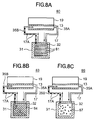
- FIGS. 8A, 8B and 8C are diagrams showing plan views of cooling units 80, 83 and 86, respectively, according to a seventh embodiment of the present invention.
- the cooling units 80, 83 and 86 according to a seventh embodiment of the present invention have essentially the same structure as the cooling unit 30 according to a third embodiment of the present invention described above, being embodiments in which an air bubble generation promoting member promoting air bubble generation is provided in the heat sink.
- a multiplicity of horn-shaped pins 81 are provided inside the heat sink 32 as air bubble generation promoting members.
- a net-like member 84 is provided inside the heat sink 32 as an air bubble generation promoting member.
- a multiplicity of small particles 87 are scattered about within the heat sink as air bubble generation promoting members.
- a member having a roughed surface may be provided on an interior wall of the heat sink 32 as an air bubble generation promoting member.
- FIGS. 9A, 9B and 9C are diagrams showing plan views of cooling units 90, 93 and 96, respectively, according to an eighth embodiment of the present invention.
- a multiplicity of parallel fins 91 made of a heat transmitting material is provided in the heat sink as heat transmission promoting members promoting transmission of heat to a liquid coolant 17.
- the contact surface area between the heat sink 32 and the liquid coolant 17 is increased, thus increasing the capacity of the heat sink 32 to receive heat and, accordingly, increasing the cooling of the heat-emitting member 16.
- the cooling unit 93 shown in FIG. 9B has a number of grooves 94 formed on the interior wall of the heat sink 32 as heat transmission promoting members promoting transmission of heat to a liquid coolant 17.
- a multiplicity of fins 97 is provided on upper and lower inner surfaces of the heat sink 32 as heat transmission promoting members promoting transmission of heat to the liquid coolant 17.
- the surface area of contact between the liquid coolant 17 and the heat sink 32 can be improved, the capacity of the heat sink to receive heat can be improved.
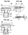
- FIGS. 10A, 10B and 10C are diagrams showing plan and side views of one cooling unit 300 and a plan view of another cooling unit 310, respectively, according to a ninth embodiment of the present invention.
- the cooling units 300 and 310 according to the ninth embodiment of the present invention have essentially the same structure as the cooling unit 30 according to the third embodiment of the present invention described above, having a flow path for the purpose of efficiently transmitting heat to a liquid coolant 17 within a heat sink 32, so that the liquid coolant 17 flowing from a radiator 13 fully absorbs heat before being returned to the radiator 13.
- the cooling unit 300 shown in FIGS. 10A and 10B is provided with dividing panels 301 and 302 inside the heat sink 32.
- These dividing panels 301, 302 provided inside the heat sink 32 are disposed so that the liquid coolant 17 that has been cooled by and is returning from the radiator 13 rises once more toward the radiator 13 only after fully absorbing heat.
- the dividing panels 301, 302 are disposed alternately so that the cooled heavy liquid coolant 17 returning from the radiator 13 falls through the inside of the heat sink in stages.
- the cooling unit 310 shown in FIG. 10C also has dividing panels 311, 312 disposed inside the heat sink 32 so as to form a flow path, with the cooled heavy liquid coolant 17 returning from the radiator 13 falling through the interior of the heat sink 32 after which the liquid coolant 17 absorbs heat and once again rises toward the radiator 13.
- the cooling unit 310 can efficiently transfer heat from the heat sink 32 to the radiator 13 without disrupting the flow of the liquid coolant 17.
- FIGS. 11A and 11B are diagrams showing plan views of cooling units 320 and 330, respectively, according to a tenth embodiment of the present invention.
- the cooling units 320 and 330 according to the tenth embodiment of the present invention have essentially the same structure as the cooling unit 30 according to the third embodiment of the present invention described above, a member for improving heat radiation being provided on a radiator 13.
- the radiator 13 is equipped with a radiative plate 321 having an enlarged surface area, by means of which the radiative effect at the radiator 13 can be increased.
- the cooling unit 330 shown in FIG. 11B is also equipped with a radiative fin 331 on the radiator 13. With this type of radiating member, too, the radiative effect at the radiator 13 can be increased.
- FIGS. 12A and 12B are diagrams showing plan views of cooling units 340 and 350, respectively, according to an eleventh embodiment of the present invention.
- the cooling units 340 and 350 according to the tenth embodiment of the present invention have essentially the same structure as the cooling unit 30 according to the third embodiment of the present invention described above, a heat removing means for efficiently removing heat from a liquid coolant 17 being provided inside a radiator 13.
- a multiplicity of heat-receiving fins 341 as heat removing means is provided on an interior surface of the radiator 13. Accordingly, a surface area of contact between the radiator 13 and the hot liquid coolant 17 is thus increased so it is possible to remove heat from the liquid coolant 17 efficiently, and accordingly, the cooling effectiveness of the cooling unit as a whole can be improved.
- a multiplicity of dividing panels 352 made of thermally conductive material are provided as heat removing means at a region in the interior of the radiator 13 that contacts the liquid coolant 17, thereby forming a heat-removing flow path 351 between the dividing panels 352.
- the radiating member 353, together with the dividing panels 352 and the heat-removing flow path 351, are given the shape of the teeth of a comb so as to better radiate and remove heat, thus improving the cooling effectiveness of the cooling unit as a whole.
Landscapes
- Engineering & Computer Science (AREA)
- Life Sciences & Earth Sciences (AREA)
- Sustainable Development (AREA)
- Physics & Mathematics (AREA)
- Thermal Sciences (AREA)
- Mechanical Engineering (AREA)
- General Engineering & Computer Science (AREA)
- Cooling Or The Like Of Electrical Apparatus (AREA)
- Cooling Or The Like Of Semiconductors Or Solid State Devices (AREA)
- Heat-Exchange Devices With Radiators And Conduit Assemblies (AREA)
- Arrangement Of Elements, Cooling, Sealing, Or The Like Of Lighting Devices (AREA)
- Projection Apparatus (AREA)
Abstract
Description
Claims (11)
- A cooling unit (10) characterized by having:a heat receiving unit (11) that receives heat from a body radiating heat (16);a radiating unit (13) disposed at a distance from the heat receiving unit (11) and radiating recovered heat;a liquid coolant (17) transporting heat generated at the heat receiving unit (11) to the radiating unit (13); anda hollow tube (15) disposed so that the liquid coolant (17) circulates between the heat receiving unit (11) and the radiating unit (13),a circulating flow of the liquid coolant (17) formed by an elevating force of air bubbles (17A) generated from the heat received at the heat receiving unit (11), the radiating unit (13) having an air pocket (14) forming one part of the circulation path of the liquid coolant (17) together with the hollow tube (15) and capable of collecting the air bubbles (17A).
- The cooling unit (20) as claimed in claim 1, characterized in that the hollow tube (15) has a bent portion (15C) inside of the heat receiving unit (11), the bent portion (15C) formed so as to expand a surface area contacting an inner surface of the heat receiving unit (11).
- The cooling unit (30) as claimed in claim 1, characterized in that the heat receiving unit (11) includes a heat sink (32) forming one part of the circulation path of the liquid coolant (17) together with the hollow tube (15) and the radiator (13) and capable of collecting a predetermined amount of the liquid coolant (17).
- The cooling unit (40) as claimed in claim 3, characterized in that two hollow tubes (45A, 45B) connect the heat sink (32) and the radiator (13), one of the hollow tubes (45B) having a diameter larger than a diameter of the other hollow tube (45A).
- The cooling unit (50) as claimed in claim 3, characterized in that two hollow tubes (55A, 55B) connect the heat sink (32) and the radiator (13), one of the hollow tubes (55B) having a length shorter than a length of the other hollow tube (55A).
- The cooling unit (70; 75) as claimed in claim 3, characterized in that two hollow tubes (71A, 71B; 76A, 76B) connect the heat sink (32) and the radiator (13), one of the hollow tubes (71A, 76A) disposed at a height higher than a height of the other hollow tube (71B, 76B).
- The cooling unit (80; 83; 86) as claimed in claim 3, characterized in that an air bubble generation promoting member (81; 84; 87) promoting air bubble generation is provided in the heat sink (32).
- The cooling unit (90; 93; 96) as claimed in claim 3, characterized in that a heat transmission promoting member (91; 94; 97) promoting transmission of heat to the liquid coolant (17) is provided in the heat sink (32).
- The cooling unit (300; 310) as claimed in claim 3, characterized in that a flow path is provided in the heat sink (32) so that the liquid coolant (17) flowing from the radiator (13) fully absorbs heat before being returned to the radiator (13).
- The cooling unit (320; 330) as claimed in claim 3, characterized in that a member (321; 331) for improving heat radiation is provided on the radiator (13).
- The cooling unit (340; 350) as claimed in claim 3, characterized in that heat removing means (341; 352) for efficiently removing heat from the liquid coolant (17) is provided inside the radiator (13).
Applications Claiming Priority (2)
| Application Number | Priority Date | Filing Date | Title |
|---|---|---|---|
| JP25079699A JP3964580B2 (en) | 1999-09-03 | 1999-09-03 | Cooling unit |
| JP25079699 | 1999-09-03 |
Publications (2)
| Publication Number | Publication Date |
|---|---|
| EP1081759A2 true EP1081759A2 (en) | 2001-03-07 |
| EP1081759A3 EP1081759A3 (en) | 2003-08-27 |
Family
ID=17213185
Family Applications (1)
| Application Number | Title | Priority Date | Filing Date |
|---|---|---|---|
| EP00303110A Withdrawn EP1081759A3 (en) | 1999-09-03 | 2000-04-13 | Cooling unit |
Country Status (3)
| Country | Link |
|---|---|
| US (3) | US6564861B1 (en) |
| EP (1) | EP1081759A3 (en) |
| JP (1) | JP3964580B2 (en) |
Cited By (4)
| Publication number | Priority date | Publication date | Assignee | Title |
|---|---|---|---|---|
| US6608751B2 (en) * | 2000-12-26 | 2003-08-19 | Fujitsu Limited | Electronic device |
| EP1793422A2 (en) | 2005-11-30 | 2007-06-06 | Raython Company | System and method of enhanced boiling heat transfer using pin fins |
| CN103424019A (en) * | 2012-05-23 | 2013-12-04 | 株式会社东芝 | Natural circulation type cooling apparatus |
| US9383145B2 (en) | 2005-11-30 | 2016-07-05 | Raytheon Company | System and method of boiling heat transfer using self-induced coolant transport and impingements |
Families Citing this family (33)
| Publication number | Priority date | Publication date | Assignee | Title |
|---|---|---|---|---|
| JP3964580B2 (en) * | 1999-09-03 | 2007-08-22 | 富士通株式会社 | Cooling unit |
| GB2389174B (en) * | 2002-05-01 | 2005-10-26 | Rolls Royce Plc | Cooling systems |
| US7209355B2 (en) | 2002-05-15 | 2007-04-24 | Matsushita Electric Industrial Co., Ltd. | Cooling device and an electronic apparatus including the same |
| JP4032954B2 (en) * | 2002-07-05 | 2008-01-16 | ソニー株式会社 | COOLING DEVICE, ELECTRONIC DEVICE DEVICE, SOUND DEVICE, AND COOLING DEVICE MANUFACTURING METHOD |
| JP4214881B2 (en) * | 2003-01-21 | 2009-01-28 | 三菱電機株式会社 | Bubble pump type heat transport equipment |
| CN1326237C (en) * | 2003-09-04 | 2007-07-11 | 珍通科技股份有限公司 | Round Tube Radiator Structure |
| DE20314532U1 (en) * | 2003-09-16 | 2004-02-19 | Pries, Wulf H. | Device for dissipating heat from electronic and electrical components |
| US7941993B2 (en) * | 2003-10-14 | 2011-05-17 | Rolls-Royce Plc | Engine cooling |
| GB0323993D0 (en) * | 2003-10-14 | 2003-11-19 | Rolls Royce Plc | Engine cooling |
| CN1902754B (en) * | 2003-12-08 | 2010-05-26 | 诺伊斯利米特公司 | Cooling system with air bubble pump |
| EP1607707A1 (en) * | 2004-06-18 | 2005-12-21 | Ecole Polytechnique Federale De Lausanne (Epfl) | Bubble generator and heat transfer assembly |
| EP1836449A1 (en) * | 2005-01-03 | 2007-09-26 | Noise Limit ApS | A multi-orientational cooling system with a bubble pump |
| JPWO2007086418A1 (en) * | 2006-01-26 | 2009-06-18 | 株式会社小松製作所 | Fluid cooling device |
| US20080283221A1 (en) * | 2007-05-15 | 2008-11-20 | Christian Blicher Terp | Direct Air Contact Liquid Cooling System Heat Exchanger Assembly |
| US9074825B2 (en) | 2007-09-28 | 2015-07-07 | Panasonic Intellectual Property Management Co., Ltd. | Heatsink apparatus and electronic device having the same |
| US20090323276A1 (en) * | 2008-06-25 | 2009-12-31 | Mongia Rajiv K | High performance spreader for lid cooling applications |
| JP5757086B2 (en) | 2008-10-29 | 2015-07-29 | 日本電気株式会社 | COOLING STRUCTURE, ELECTRONIC DEVICE, AND COOLING METHOD |
| JP5412815B2 (en) * | 2008-12-04 | 2014-02-12 | 富士通株式会社 | Cooling jacket, cooling unit, cooling system and electronic equipment |
| ATE554643T1 (en) * | 2009-08-05 | 2012-05-15 | Abb Research Ltd | EVAPORATOR AND COOLING CIRCUIT |
| CN102869943A (en) * | 2010-05-19 | 2013-01-09 | 日本电气株式会社 | Ebullient cooling device |
| WO2012060461A1 (en) * | 2010-11-02 | 2012-05-10 | 日本電気株式会社 | Cooling device and manufacturing method thereof |
| WO2012115214A1 (en) * | 2011-02-22 | 2012-08-30 | 日本電気株式会社 | Cooling device and method for producing same |
| JP5809835B2 (en) | 2011-04-14 | 2015-11-11 | ニチアス株式会社 | Cutting device |
| JP5618419B2 (en) | 2011-06-13 | 2014-11-05 | 株式会社日立製作所 | Boiling cooling system |
| JP5252059B2 (en) * | 2011-10-11 | 2013-07-31 | パナソニック株式会社 | Cooling system |
| US20130118715A1 (en) * | 2011-11-10 | 2013-05-16 | Troy W. Livingston | Heat transfer system applying boundary later penetration |
| US20160377356A1 (en) * | 2015-06-25 | 2016-12-29 | Asia Vital Components Co., Ltd. | Flexible and transformable water-cooling device |
| CA2998897C (en) * | 2017-03-24 | 2021-02-23 | James W. Dobson | Passive heat recovery or defrosting device using a closed loop heat transfer circuit |
| US10966348B2 (en) * | 2017-04-04 | 2021-03-30 | Mitsubishi Electric Corporation | Semiconductor cooling device, power control system and travelling body including a semiconductor colling device with microbubble generator |
| US10813246B2 (en) * | 2017-10-23 | 2020-10-20 | Asia Vital Components (China) Co., Ltd. | Chassis heat dissipation structure |
| TWI685638B (en) * | 2018-09-14 | 2020-02-21 | 財團法人工業技術研究院 | Three dimensional pulsating heat pipe, three dimensional pulsating heat pipe assembly and heat dissipation module |
| CN109378301B (en) * | 2018-10-10 | 2020-08-25 | 江门市久欣光电有限公司 | A chip package and preparation method thereof |
| CN115087300A (en) | 2021-03-12 | 2022-09-20 | 华为技术有限公司 | Gas collection device |
Family Cites Families (40)
| Publication number | Priority date | Publication date | Assignee | Title |
|---|---|---|---|---|
| FR1319387A (en) * | 1962-01-17 | 1963-03-01 | Chausson Usines Sa | Method and device for cooling semiconductor elements, in particular transistors |
| US3609991A (en) * | 1969-10-13 | 1971-10-05 | Ibm | Cooling system having thermally induced circulation |
| JPS5723194B2 (en) * | 1973-08-17 | 1982-05-17 | ||
| JPS5512740B2 (en) * | 1974-03-15 | 1980-04-03 | ||
| JPS5241193B2 (en) * | 1974-03-16 | 1977-10-17 | ||
| JPS5812509B2 (en) * | 1975-09-20 | 1983-03-08 | 株式会社日立製作所 | Kaihougatutututoreikiyakusouchi |
| JPS54128286A (en) * | 1978-03-29 | 1979-10-04 | Hitachi Ltd | Boiling cooler |
| JPS5563397A (en) | 1978-10-31 | 1980-05-13 | Mitsubishi Electric Corp | Manufacture of bolling heat transmission surface |
| JPS55118561A (en) * | 1979-03-05 | 1980-09-11 | Hitachi Ltd | Constant pressure type boiling cooler |
| JPS6011838B2 (en) | 1980-03-13 | 1985-03-28 | 株式会社東芝 | Boiling cooler |
| JPS5994445A (en) * | 1982-11-20 | 1984-05-31 | Mitsubishi Electric Corp | Natural circulation type boiling cooler |
| DE3410767A1 (en) * | 1983-03-24 | 1984-10-04 | Uop Inc., Des Plaines, Ill. | Raised core-forming vapour deposition surface band and cooling of electronic subassemblies |
| JPS60148588U (en) * | 1984-03-14 | 1985-10-02 | 株式会社東芝 | refrigerator |
| JPS6131884A (en) * | 1984-07-24 | 1986-02-14 | Kenji Okayasu | Heat transfer device |
| DE3877438T2 (en) * | 1987-07-10 | 1993-06-03 | Hitachi Ltd | SEMICONDUCTOR REFRIGERATOR. |
| JPH02122554A (en) | 1988-10-31 | 1990-05-10 | Mitsubishi Electric Corp | Boiling and cooling apparatus |
| EP0456508A3 (en) * | 1990-05-11 | 1993-01-20 | Fujitsu Limited | Immersion cooling coolant and electronic device using this coolant |
| JP2859927B2 (en) * | 1990-05-16 | 1999-02-24 | 株式会社東芝 | Cooling device and temperature control device |
| US5285347A (en) * | 1990-07-02 | 1994-02-08 | Digital Equipment Corporation | Hybird cooling system for electronic components |
| US5106451A (en) * | 1990-11-15 | 1992-04-21 | International Business Machines Corporation | Heat sink and method of attachment |
| US5219020A (en) * | 1990-11-22 | 1993-06-15 | Actronics Kabushiki Kaisha | Structure of micro-heat pipe |
| US5289869A (en) * | 1992-12-17 | 1994-03-01 | Klein John F | Closed loop feedback control variable conductance heat pipe |
| US5394936A (en) * | 1993-03-12 | 1995-03-07 | Intel Corporation | High efficiency heat removal system for electric devices and the like |
| US5458189A (en) * | 1993-09-10 | 1995-10-17 | Aavid Laboratories | Two-phase component cooler |
| JPH07127982A (en) | 1993-11-04 | 1995-05-19 | Nippon Telegr & Teleph Corp <Ntt> | Heat transport pipe |
| JP3385482B2 (en) * | 1993-11-15 | 2003-03-10 | 株式会社日立製作所 | Electronics |
| US5634351A (en) * | 1994-03-24 | 1997-06-03 | Aavid Laboratories, Inc. | Two-phase cooling system for a laptop computer lid |
| JP3451737B2 (en) * | 1994-09-06 | 2003-09-29 | 株式会社デンソー | Boiling cooling device |
| SE503322C2 (en) | 1995-03-17 | 1996-05-28 | Ericsson Telefon Ab L M | Cooling system for electronics |
| US5606341A (en) * | 1995-10-02 | 1997-02-25 | Ncr Corporation | Passive CPU cooling and LCD heating for a laptop computer |
| US6104611A (en) * | 1995-10-05 | 2000-08-15 | Nortel Networks Corporation | Packaging system for thermally controlling the temperature of electronic equipment |
| JPH09246411A (en) | 1996-03-04 | 1997-09-19 | Iwate Toshiba Electron Kk | Semiconductor marking method and semiconductor marking device |
| JP3810119B2 (en) | 1996-03-07 | 2006-08-16 | 株式会社デンソー | Boiling cooler |
| US6173761B1 (en) * | 1996-05-16 | 2001-01-16 | Kabushiki Kaisha Toshiba | Cryogenic heat pipe |
| JP3210261B2 (en) | 1996-12-06 | 2001-09-17 | 株式会社東芝 | Boiling cooling device and manufacturing method thereof |
| US6005772A (en) * | 1997-05-20 | 1999-12-21 | Denso Corporation | Cooling apparatus for high-temperature medium by boiling and condensing refrigerant |
| TW331586B (en) * | 1997-08-22 | 1998-05-11 | Biing-Jiun Hwang | Network-type heat pipe device |
| JP2911441B1 (en) * | 1998-04-03 | 1999-06-23 | 伊藤 さとみ | Heat pipe, method of manufacturing the same, and heat dissipation structure using the same |
| JP3964580B2 (en) * | 1999-09-03 | 2007-08-22 | 富士通株式会社 | Cooling unit |
| US6820683B1 (en) * | 2000-01-04 | 2004-11-23 | Li Jia Hao | Bubble cycling heat exchanger |
-
1999
- 1999-09-03 JP JP25079699A patent/JP3964580B2/en not_active Expired - Fee Related
-
2000
- 2000-04-12 US US09/548,426 patent/US6564861B1/en not_active Expired - Fee Related
- 2000-04-13 EP EP00303110A patent/EP1081759A3/en not_active Withdrawn
-
2003
- 2003-04-07 US US10/407,464 patent/US7337829B2/en not_active Expired - Fee Related
-
2007
- 2007-12-28 US US12/003,542 patent/US7828047B2/en not_active Expired - Fee Related
Cited By (6)
| Publication number | Priority date | Publication date | Assignee | Title |
|---|---|---|---|---|
| US6608751B2 (en) * | 2000-12-26 | 2003-08-19 | Fujitsu Limited | Electronic device |
| EP1793422A2 (en) | 2005-11-30 | 2007-06-06 | Raython Company | System and method of enhanced boiling heat transfer using pin fins |
| EP1793422A3 (en) * | 2005-11-30 | 2010-05-26 | Raython Company | System and method of enhanced boiling heat transfer using pin fins |
| US9383145B2 (en) | 2005-11-30 | 2016-07-05 | Raytheon Company | System and method of boiling heat transfer using self-induced coolant transport and impingements |
| CN103424019A (en) * | 2012-05-23 | 2013-12-04 | 株式会社东芝 | Natural circulation type cooling apparatus |
| CN103424019B (en) * | 2012-05-23 | 2016-02-17 | 株式会社东芝 | Natural circulation type all cooling device |
Also Published As
| Publication number | Publication date |
|---|---|
| JP3964580B2 (en) | 2007-08-22 |
| US7337829B2 (en) | 2008-03-04 |
| US20030188858A1 (en) | 2003-10-09 |
| JP2001077256A (en) | 2001-03-23 |
| US6564861B1 (en) | 2003-05-20 |
| US20080236797A1 (en) | 2008-10-02 |
| EP1081759A3 (en) | 2003-08-27 |
| US7828047B2 (en) | 2010-11-09 |
Similar Documents
| Publication | Publication Date | Title |
|---|---|---|
| US7828047B2 (en) | Cooling unit | |
| US6459576B1 (en) | Fan based heat exchanger | |
| US20040001310A1 (en) | Liquid-to-air cooling system for portable electronic and computer devices | |
| JP2004056151A (en) | Thermosyphon for electronics cooled with uneven air flow | |
| US6608751B2 (en) | Electronic device | |
| EP1708263B1 (en) | Cooling jacket | |
| JP5262473B2 (en) | Electronic equipment and its components | |
| CN100399230C (en) | liquid cooling system | |
| CN120161922A (en) | Gravity cooling device | |
| JPH08303971A (en) | Flat heat pipe for cooling portable personal computer and manufacturing method thereof | |
| JP2004047922A (en) | Electronic equipment cooling device | |
| JPH08303972A (en) | Flat heat pipe for cooling portable personal computer and its manufacturing method | |
| CN218550265U (en) | Circuit board heat dissipation device and electronic equipment | |
| JP4521250B2 (en) | Heat dissipation device and manufacturing method thereof | |
| JP2005011928A (en) | Liquid cooling circulation system | |
| CN113110723B (en) | Heat dissipation mechanism and server | |
| JP3098104U (en) | Built-in heat dissipation container for electrical products | |
| US20050092468A1 (en) | Water tray of liquid based cooling device | |
| TWI898603B (en) | Desktop computer with hybrid cooling | |
| JP2002043490A (en) | Liquid-cooled integrated circuit cooling device | |
| JP2006235914A (en) | Liquid cooling system and small electronic device equipped with the system | |
| TW200531617A (en) | Heat dissipation device with heat pipes | |
| CN222210844U (en) | An integrated preheating pump-driven two-phase flow system | |
| JPH08303970A (en) | Flat heat pipe for cooling portable personal computer and manufacturing method thereof | |
| JP2001127225A (en) | Cooling apparatus and cooling method for electronic equipment |
Legal Events
| Date | Code | Title | Description |
|---|---|---|---|
| PUAI | Public reference made under article 153(3) epc to a published international application that has entered the european phase |
Free format text: ORIGINAL CODE: 0009012 |
|
| AK | Designated contracting states |
Kind code of ref document: A2 Designated state(s): AT BE CH CY DE DK ES FI FR GB GR IE IT LI LU MC NL PT SE |
|
| AX | Request for extension of the european patent |
Free format text: AL;LT;LV;MK;RO;SI |
|
| PUAL | Search report despatched |
Free format text: ORIGINAL CODE: 0009013 |
|
| AK | Designated contracting states |
Designated state(s): AT BE CH CY DE DK ES FI FR GB GR IE IT LI LU MC NL PT SE |
|
| AX | Request for extension of the european patent |
Extension state: AL LT LV MK RO SI |
|
| 17P | Request for examination filed |
Effective date: 20031222 |
|
| 17Q | First examination report despatched |
Effective date: 20040216 |
|
| AKX | Designation fees paid |
Designated state(s): DE GB |
|
| STAA | Information on the status of an ep patent application or granted ep patent |
Free format text: STATUS: THE APPLICATION IS DEEMED TO BE WITHDRAWN |
|
| 18D | Application deemed to be withdrawn |
Effective date: 20101123 |