EP1081427B1 - Scheinwerfer für Fahrzeuge - Google Patents
Scheinwerfer für Fahrzeuge Download PDFInfo
- Publication number
- EP1081427B1 EP1081427B1 EP00118703A EP00118703A EP1081427B1 EP 1081427 B1 EP1081427 B1 EP 1081427B1 EP 00118703 A EP00118703 A EP 00118703A EP 00118703 A EP00118703 A EP 00118703A EP 1081427 B1 EP1081427 B1 EP 1081427B1
- Authority
- EP
- European Patent Office
- Prior art keywords
- bed
- reflector
- seal
- headlamp according
- adhesive
- Prior art date
- Legal status (The legal status is an assumption and is not a legal conclusion. Google has not performed a legal analysis and makes no representation as to the accuracy of the status listed.)
- Expired - Lifetime
Links
- 239000000853 adhesive Substances 0.000 claims abstract description 20
- 230000001070 adhesive effect Effects 0.000 claims abstract description 20
- 230000002093 peripheral effect Effects 0.000 claims 3
- 239000000126 substance Substances 0.000 claims 3
- 239000000463 material Substances 0.000 abstract 1
- NJPPVKZQTLUDBO-UHFFFAOYSA-N novaluron Chemical compound C1=C(Cl)C(OC(F)(F)C(OC(F)(F)F)F)=CC=C1NC(=O)NC(=O)C1=C(F)C=CC=C1F NJPPVKZQTLUDBO-UHFFFAOYSA-N 0.000 description 3
- 238000004026 adhesive bonding Methods 0.000 description 1
- 239000003086 colorant Substances 0.000 description 1
Images
Classifications
-
- B—PERFORMING OPERATIONS; TRANSPORTING
- B60—VEHICLES IN GENERAL
- B60Q—ARRANGEMENT OF SIGNALLING OR LIGHTING DEVICES, THE MOUNTING OR SUPPORTING THEREOF OR CIRCUITS THEREFOR, FOR VEHICLES IN GENERAL
- B60Q1/00—Arrangement of optical signalling or lighting devices, the mounting or supporting thereof or circuits therefor
- B60Q1/02—Arrangement of optical signalling or lighting devices, the mounting or supporting thereof or circuits therefor the devices being primarily intended to illuminate the way ahead or to illuminate other areas of way or environments
- B60Q1/04—Arrangement of optical signalling or lighting devices, the mounting or supporting thereof or circuits therefor the devices being primarily intended to illuminate the way ahead or to illuminate other areas of way or environments the devices being headlights
- B60Q1/0483—Arrangement of optical signalling or lighting devices, the mounting or supporting thereof or circuits therefor the devices being primarily intended to illuminate the way ahead or to illuminate other areas of way or environments the devices being headlights mounted on a bracket, e.g. details concerning the mouting of the lamps on the vehicle body
-
- F—MECHANICAL ENGINEERING; LIGHTING; HEATING; WEAPONS; BLASTING
- F21—LIGHTING
- F21S—NON-PORTABLE LIGHTING DEVICES; SYSTEMS THEREOF; VEHICLE LIGHTING DEVICES SPECIALLY ADAPTED FOR VEHICLE EXTERIORS
- F21S41/00—Illuminating devices specially adapted for vehicle exteriors, e.g. headlamps
- F21S41/20—Illuminating devices specially adapted for vehicle exteriors, e.g. headlamps characterised by refractors, transparent cover plates, light guides or filters
- F21S41/29—Attachment thereof
-
- F—MECHANICAL ENGINEERING; LIGHTING; HEATING; WEAPONS; BLASTING
- F21—LIGHTING
- F21W—INDEXING SCHEME ASSOCIATED WITH SUBCLASSES F21K, F21L, F21S and F21V, RELATING TO USES OR APPLICATIONS OF LIGHTING DEVICES OR SYSTEMS
- F21W2102/00—Exterior vehicle lighting devices for illuminating purposes
- F21W2102/30—Fog lights
Definitions
- the invention relates to a headlight for vehicles, which is fastened to the outside of the vehicle by means of a holder, with a light insert inserted into a housing, which has a reflector and a bonded to a front edge region of the reflector lens, which together with the reflector to the housing limited circulating receiving bed for an adhesive limited.
- Such a headlight for vehicles is known from DE 197 28 446 C1.
- the headlight is used for fog or high beam and can be fixed by a holder from the outside of the vehicle.
- the holder carries a plastic shell-shaped housing in which a light insert is inserted from its front side.
- the light insert consists essentially of a cup-shaped reflector of a reflector associated lamp and a front opening of the reflector occlusive lens.
- the closure plate has at its outer edge a directed towards the housing, circumferential side wall.
- On the inside of the lens of the reflector is located with its front edge and forms together with the outer side wall of the lens a rotating recording bed for an adhesive.
- the bowl-shaped reflector has an elliptical light exit surface and limits the receiving bed by its wall forming the shell.
- the receiving bed varies circumferentially in its width. Since there is great play between the front edge of the reflector and the outer side wall of the lens due to large tolerances, an accurate positioning of the reflector to the lens is not sure. Furthermore, it can flow unevenly through to the curing of the adhesive between the front edge region and the lens and it creates a clearly visible from the front side of the headlamp impure gluing, which is not responsible for decorative reasons.
- the object of the invention is to make the described in the preamble of claim 1 headlights for vehicles such that even with between reflector and lens existing large tolerances always accurate positioning of both parts is safe and beyond the front of the headlamp forth no adhesive you can see.
- This object is achieved according to the invention in that between the adhesive and the bottom of the receiving bed circumferentially a seal is arranged, which extends adjacent to facing side walls of the receiving bed and for the adhesive is the bottom of the receiving bed. After introduction of the seal in the receiving bed of the reflector is radially aligned exactly to the lens. In the remaining space of the receiving bed of the adhesive is introduced, which, even if it is thin until its curing, because of the seal can not flow to the inside of the lens.
- the reflector and the lens are also held to each other before the introduction of the adhesive and the curing of the adhesive when the seal bears under pretension on the facing side walls of the receiving bed.
- the reflector is held in the direction of its light exit exactly to the lens, when the reflector is limited at its front edge with a circumferential radial edge portion of the receiving bed at its base and applied to a mounted on the inside of the lens disc rotating pedestal.
- the exact position of the reflector to the lens is safe when the seal is so deeply pressed into the receiving bed until the reflector abuts with its radially extending edge portion of the pedestal of the lens.
- the facing side walls of the receiving bed run circumferentially in an equidistant distance from each other and the receiving bed is designed in its cross-section U-shaped.
- the facing side walls of the receiving bed run circumferentially in an equidistant distance from each other and the receiving bed is designed in its cross-section U-shaped.
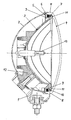
- FIG. 1 An embodiment of the invention is shown in the drawing, which shows a headlight for vehicles in a vertical central section, which can be fastened by means of a holder on the outside of the vehicle.
- the headlight has a cup-shaped housing 2 made of plastic, in which a light insert consisting of a reflector 3 and a lens 4 is inserted.
- the reflector 3 is designed shell-shaped and made of plastic.
- a holding lug 12 is formed, which projects through an opening of the housing 2 and which is fixedly connected to a fastened to the outside of the vehicle holder 1.
- the reflector 3 has in the apex region an opening for receiving a lamp 13.
- the closure plate 4 is designed shell-shaped and has at its outer edge a directed towards the housing 2 circumferential side wall 8.
- the reflector 3 has near its front edge on its rear side integrally formed on the side wall 9, which extends with a radially outwardly directed inside at an equidistant distance from the inside of the side wall 8 of the lens 4.
- the reflector 3 has at its front edge on a radially outwardly directed edge portion 10 which forms a circumferential receiving bed 5 together with the side walls 8 and 9.
- the edge portion 10 extends to close to the inside of the side wall 8 and lies flat and circumferentially on an annular pedestal 11, which is integrally formed on the inside of the lens 4.
- the receiving bed 5 is U-shaped in cross section and receives a rectangular cross-section seal 7, which at the bottom of the receiving bed. 5 and bears against the facing inner sides of the side walls 8 and 9 under prestress.
- the seal 7 is made of soft rubber. In the remaining space of the receiving bed 5, which is bounded by the seal 7 and the side walls 8 and 9, an adhesive 6 is introduced. Even if a low-viscosity adhesive is injected into the receiving bed, this can not flow until it cures because of the seal on the front inside of the lens. By the seal 7 of the adhesive 6 receiving space of the receiving bed 5 is clearly defined.
- the seal 7 can be used in different colors, whereby the headlight different appearance variations are possible.
Landscapes
- Engineering & Computer Science (AREA)
- Mechanical Engineering (AREA)
- General Engineering & Computer Science (AREA)
- Lighting Device Outwards From Vehicle And Optical Signal (AREA)
- Non-Portable Lighting Devices Or Systems Thereof (AREA)
Description
- Die Erfindung betrifft einen Scheinwerfer für Fahrzeuge, welcher außen am Fahrzeug mittels eines Halters befestigbar ist, mit einem in ein Gehäuse eingesetzten Lichteinsatz, der einen Reflektor und eine mit einem vorderen Randbereich des Reflektors verklebte Abschlußscheibe aufweist, die zusammen mit dem Reflektor ein zum Gehäuse hin geöffnetes umlaufendes Aufnahmebett für einen Klebstoff begrenzt.
- Ein solcher Scheinwerfer für Fahrzeuge ist aus der DE 197 28 446 C1 bekannt. Der Scheinwerfer dient für Nebel- oder Fernlicht und ist durch einen Halter aus außen am Fahrzeug festsetzbar. Der Halter trägt ein aus Kunststoff bestehendes schalenförmiges Gehäuse, in welches von seiner Vorderseite her ein Lichteinsatz eingesetzt ist. Der Lichteinsatz besteht im wesentlichen aus einem schalenförmigen Reflektor einer dem Reflektor zugeordneten Lampe und einer die vordere Öffnung des Reflektors verschließenden Abschlußscheibe. Die Abschlußscheibe weist an ihrem äußeren Rand eine zum Gehäuse hin gerichtete, umlaufende Seitenwand auf. An der Innenseite der Abschlußscheibe liegt der Reflektor mit seinem vorderen Rand an und bildet zusammen mit der äußeren Seitenwand der Abschlußscheibe ein umlaufendes Aufnahmebett für einen Klebstoff. Der schalenförmige Reflektor weist eine elliptische Lichtaustrittsfläche auf und begrenzt das Aufnahmebett durch seine die Schale bildende Wand. Dadurch variiert das Aufnahmebett umlaufend in seiner Breite. Da zwischen dem vorderen Rand des Reflektors und der äußeren Seitenwand der Abschlußscheibe durch große Toleranzen bedingt ein großes Spiel besteht, ist eine genaue Positionierung des Reflektors zur Abschlußscheibe nicht sicher. Weiterhin kann bis zur Aushärtung des Klebers dieser zwischen dem vorderen Randbereich und der Abschlußscheibe ungleichmäßig durchfließen und es entsteht eine von der vorderen Seite des Scheinwerfers her deutlich sichtbare unsaubere Verklebung, die ist aus dekorativen Gründen nicht zu vertreten ist.
- Aufgabe der Erfindung ist es, den im Oberbegriff des Anspruches 1 beschriebenen Scheinwerfer für Fahrzeuge derart zu gestalten, daß auch bei zwischen Reflektor und Abschlußscheibe bestehenden großen Toleranzen immer eine genaue Positionierung beider Teile zueinander sicher ist und darüber hinaus von der Vorderseite des Scheinwerfers her kein Klebstoff zu sehen ist. Diese Aufgabe wird nach der Erfindung dadurch gelöst, daß zwischen dem Klebstoff und dem Grund des Aufnahmebetts umlaufend eine Dichtung angeordnet ist, die angrenzend zu sich zugewandten Seitenwänden des Aufnahmebetts verläuft und für den Klebstoff der Grund des Aufnahmebetts ist. Nach einem Einbringen der Dichtung in das Aufnahmebett ist der Reflektor radial genau zur Abschlußscheibe ausgerichtet. In den verbleibenden Raum des Aufnahmebettes wird der Klebstoff eingebracht, der, auch wenn er bis zu seiner Aushärtung dünnflüssig ist, wegen der Dichtung nicht auf die Innenseite der Abschlußscheibe fließen kann.
- Der Reflektor und die Abschlußscheibe sind auch vor dem Einbringen des Klebstoffs und beim Aushärten des Klebstoffes zueinander gehalten, wenn die Dichtung unter Vorspannung an den sich zugewandten Seitenwänden des Aufnahmebettes anliegt. Der Reflektor ist in Richtung seines Lichtaustritts genau zur Abschlußscheibe gehalten, wenn der Reflektor an seinem vorderen Rand mit einem umlaufenden radialen Randabschnitt das Aufnahmebett an seinem Grund begrenzt und an einem an die Innenseite der Abschlußscheibe angebrachten umlaufenden Podest anliegt. Die genaue Lage des Reflektors zur Abschlußscheibe ist sicher, wenn die Dichtung so tief in das Aufnahmebett eingedrückt ist, bis der Reflektor mit seinem radial verlaufenden Randabschnitt an dem Podest der Abschlußscheibe anschlägt.
- Weiterhin ist es vorteilhaft, wenn die sich zugewandten Seitenwände des Aufnahmebettes umlaufend in einem äquidistanten Abstand zueinander verlaufen und das Aufnahmebett in seinem Querschnitt U-förmig gestaltet ist. Dadurch ist nur eine sehr geringe Klebstoffmenge notwendig, und trotzdem ist die Verbindung zwischen Reflektor und Abschlußscheibe fest und dicht. Außerdem ist in das Aufnahmebett eine Strangdichtung oder eine einfache Formdichtung mit umlaufend gleichbleibendem Querschnitt verwendbar.
- Ein Ausführungsbeispiel nach der Erfindung ist in der Zeichnung dargestellt, welche in einem vertikalen mittleren Schnitt einen Scheinwerfer für Fahrzeuge zeigt, der mittels eines Halters außen am Fahrzeug befestigbar ist.
- Der Scheinwerfer weist ein aus Kunststoff bestehendes topfförmiges Gehäuse 2 auf, in welches ein aus einem Reflektor 3 und einer Abschlußscheibe 4 bestehender Lichteinsatz eingesetzt ist. Der Reflektor 3 ist schalenförmig ausgeführt und besteht aus Kunststoff. An den Reflektor 3 ist ein Halteansatz 12 angeformt, der durch eine Öffnung des Gehäuses 2 ragt und der fest mit einem außen am Fahrzeug befestigbaren Halter 1 verbunden ist. Der Reflektor 3 weist im Scheitelbereich eine Öffnung zur Aufnahme einer Lampe 13 auf. Die Abschlußscheibe 4 ist schalenförmig ausgeführt und weist an ihrem äußeren Rand eine zum Gehäuse 2 hin gerichtete umlaufende Seitenwand 8 auf. Der Reflektor 3 weist nahe seinem vorderen Rand eine an seine Rückseite umlaufend angeformte Seitenwand 9 auf, welche mit einer radial nach außen gerichteten Innenseite in einem äquidistanten Abstand zur Innenseite der Seitenwand 8 der Abschlußscheibe 4 verläuft. Der Reflektor 3 weist an seinem vorderen Rand einen radial nach außen gerichteten Randabschnitt 10 auf, welcher zusammen mit den Seitenwänden 8 und 9 ein umlaufende Aufnahmebett 5 bildet. Der Randabschnitt 10 erstreckt sich bis nahe an die Innenseite der Seitenwand 8 und liegt flächig und umlaufend an einem ringförmigen Podest 11 an, welches an die Innenseite der Abschlußscheibe 4 angeformt ist. Das Aufnahmebett 5 ist im Querschnitt U-förmig gestaltet und nimmt eine im Querschnitt rechteckförmige Dichtung 7 auf, welche an dem Grund des Aufnahmebettes 5 und an den sich zugewandten Innenseiten der Seitenwände 8 und 9 unter Vorspannung anliegt. Die Dichtung 7 ist aus Weichgummi hergestellt. In dem verbleibenden Raum des Aufnahmebettes 5, welcher von der Dichtung 7 und den Seitenwänden 8 und 9 begrenzt ist, ist ein Klebstoff 6 eingebracht. Auch wenn ein dünnflüssiger Klebstoff in das Aufnahmebett eingespritzt wird, kann dieser bis zu seiner Aushärtung wegen der Dichtung nicht auf die vordere Innenseite der Abschlußscheibe fließen. Durch die Dichtung 7 ist der den Klebstoff 6 aufnehmende Raum des Aufnahmebetts 5 sauber abgegrenzt. Die Dichtung 7 kann in unterschiedlichen Farben verwendet werden, wodurch für den Scheinwerfer verschiedene Erscheinungsvariationen möglich sind.
Claims (8)
- Scheinwerfer für Fahrzeuge, welcher außen am Fahrzeug mittels eines Halters (1) festsetzbar ist, mit einem in ein Gehäuse (2) eingesetzten Lichteinsatz, der einen Reflektor (3) und eine mit einem vorderen Randbereich des Reflektors (3) verklebte Abschlußscheibe (4) aufweist, die zusammen mit dem Reflektor (3) ein zum Gehäuse (2) hin geöffnetes umlaufendes Aufnahmebett (5) für einen Klebstoff (6) begrenzt, dadurch gekennzeichnet, daß zwischen dem Klebstoff (6) und dem Grund des Aufnahmebetts (5) umlaufend eine Dichtung (7) angeordnet ist, die angrenzend zu sich zugewandten Seitenwänden (8 und 9) des Aufnahmebetts (5) verläuft und für den Klebstoff (6) der Grund des Aufnahmebetts (5) ist.
- Scheinwerfer nach Anspruch 1, dadurch gekennzeichnet, daß die Dichtung (7) unter Vorspannung an den sich zugewandten Seitenwänden (8 und 9) des Aufnahmebetts (5) anliegt.
- Scheinwerfer nach Anspruch 1 oder 2, dadurch gekennzeichnet, daß die sich zugewandten Seitenwände (8 und 9) des Aufnahmebetts (5) mit ihren Innenseiten umlaufend in einem äquidistanten Abstand zueinander verlaufen.
- Scheinwerfer nach Anspruch 3, dadurch gekennzeichnet, daß das Aufnahmebett (5) in seinem Querschnitt U-förmig verläuft.
- Scheinwerfer nach Anspruch 4, dadurch gekennzeichnet, daß die Dichtung (7) im Querschnitt rechteckförmig gestaltet ist.
- Scheinwerfer nach einem der Ansprüche 2 bis 5, dadurch gekennzeichnet, daß eine Seitenwand (8) des Aufnahmebetts (5) von einem seitlichen Randabschnitt der Abschlußscheibe (4) gebidet ist, während die andere Seitenwand (9) zumindest abschnittsweise an die Rückseite des Reflektors (3) angebracht ist.
- Scheinwerfer nach einem der vorstehenden Ansprüche, dadurch gekennzeichnet, daß der Reflektor (3) an seinem vorderen Rand mit einem umlaufenden radialen Randabschnitt (10) das Aufnahmebett (5) an seinem Grund begrenzt und an einem Podest (1)1 der Innenseite der Abschlußscheibe (4) anliegt.
- Scheinwerfer nach einem der vorstehenden Ansprüche, dadurch gekennzeichnet, daß die Dichtung (7) aus Weichgummi besteht.
Applications Claiming Priority (2)
| Application Number | Priority Date | Filing Date | Title |
|---|---|---|---|
| DE19941523 | 1999-09-01 | ||
| DE19941523A DE19941523A1 (de) | 1999-09-01 | 1999-09-01 | Scheinwerfer für Fahrzeuge |
Publications (3)
| Publication Number | Publication Date |
|---|---|
| EP1081427A2 EP1081427A2 (de) | 2001-03-07 |
| EP1081427A3 EP1081427A3 (de) | 2004-01-21 |
| EP1081427B1 true EP1081427B1 (de) | 2006-07-26 |
Family
ID=7920337
Family Applications (1)
| Application Number | Title | Priority Date | Filing Date |
|---|---|---|---|
| EP00118703A Expired - Lifetime EP1081427B1 (de) | 1999-09-01 | 2000-08-30 | Scheinwerfer für Fahrzeuge |
Country Status (4)
| Country | Link |
|---|---|
| EP (1) | EP1081427B1 (de) |
| AT (1) | ATE334339T1 (de) |
| DE (2) | DE19941523A1 (de) |
| ES (1) | ES2269049T3 (de) |
Family Cites Families (3)
| Publication number | Priority date | Publication date | Assignee | Title |
|---|---|---|---|---|
| DE29604137U1 (de) * | 1996-03-06 | 1997-07-03 | Robert Bosch Gmbh, 70469 Stuttgart | Zusatzscheinwerfer für Fahrzeuge |
| DE19728446C1 (de) * | 1997-07-03 | 1999-01-28 | Hella Kg Hueck & Co | Kraftfahrzeugscheinwerfer mit einem Gehäuse und mit einer Befestigungsvorrichtung und ein Verfahren zum Zusammenbau eines solchen Kraftfahrzeugscheinwerfers |
| DE29809618U1 (de) * | 1998-05-28 | 1998-07-30 | Hella Kg Hueck & Co | Scheinwerfer für Fahrzeuge, insbesondere Zusatzscheinwerfer für Kraftfahrzeuge |
-
1999
- 1999-09-01 DE DE19941523A patent/DE19941523A1/de not_active Withdrawn
-
2000
- 2000-08-30 ES ES00118703T patent/ES2269049T3/es not_active Expired - Lifetime
- 2000-08-30 EP EP00118703A patent/EP1081427B1/de not_active Expired - Lifetime
- 2000-08-30 DE DE50013220T patent/DE50013220D1/de not_active Expired - Lifetime
- 2000-08-30 AT AT00118703T patent/ATE334339T1/de not_active IP Right Cessation
Also Published As
| Publication number | Publication date |
|---|---|
| DE19941523A1 (de) | 2001-03-08 |
| EP1081427A3 (de) | 2004-01-21 |
| ES2269049T3 (es) | 2007-04-01 |
| ATE334339T1 (de) | 2006-08-15 |
| DE50013220D1 (de) | 2006-09-07 |
| EP1081427A2 (de) | 2001-03-07 |
Similar Documents
| Publication | Publication Date | Title |
|---|---|---|
| DE19528474A1 (de) | Ultraschallwandler mit Halteeinrichtung für Halterung mit Stoßfänger eines Kraftfahrzeugs | |
| DE3512882C2 (de) | ||
| DE102011089243B4 (de) | Magnetrad | |
| EP0160918A2 (de) | Einrichtung zur Befestigung einer Beleuchtungseinheit an einer Kraftfahrzeugkarosserie | |
| DE19728446C1 (de) | Kraftfahrzeugscheinwerfer mit einem Gehäuse und mit einer Befestigungsvorrichtung und ein Verfahren zum Zusammenbau eines solchen Kraftfahrzeugscheinwerfers | |
| EP1081427A2 (de) | Scheinwerfer für Fahrzeuge | |
| DE4128534C1 (en) | Pivotable fixture for reflector of motor vehicle headlamp - provides pivotable point by pressed recess in outer housing edge serving as spring for groove in outer reflector edge | |
| DE3231364A1 (de) | Belueftungsvorrichtung fuer die bremse in einem kraftfahrzeug | |
| DE3401437C2 (de) | Baugruppe eines Fahrzeug-Scheinwerfers | |
| DE2217277C2 (de) | Glühlampenfassung, insbesondere für Kraftfahrzeug Scheinwerfer | |
| DE3836032C2 (de) | Einkammerleuchte für Kraftfahrzeuge | |
| DE2850296C3 (de) | Verfahren zum Herstellen eines Kraftfahrzeugscheinwerfers | |
| DE4445187A1 (de) | Scheinwerfer für Fahrzeuge | |
| DE69108473T2 (de) | Lampenanordnung. | |
| DE4414899C1 (de) | Abdeckeinheit für ein Reflektoren aufnehmendes Gehäuse einer Lichteinheit für Kraftfahrzeuge | |
| DE102013101024B4 (de) | Beleuchtungsvorrichtung für Fahrzeuge | |
| DE2940249A1 (de) | Kunststoffreflektor fuer scheinwerfer | |
| DE1109623B (de) | Einbauscheinwerfer | |
| DE202015104989U1 (de) | Optischer Einsatz für ein Leuchtengehäuse, Leuchtengehäuse und Leuchte mit einem optischen Einsatz und einem Leuchtengehäuse | |
| DE60129490T2 (de) | Kfz-Scheinwerfer mit Maske und Korrektur | |
| DE4106261A1 (de) | Scheinwerfer fuer fahrzeuge | |
| DE2124944A1 (de) | Fährzeugscheinwerfer | |
| DE7321276U (de) | Trockenfilter, insbesondere für Kraftfahrzeuge | |
| DE1986511U (de) | Schweinwerfer fuer kraftfahrzeuge. | |
| DE734265C (de) | Strassenverkehrssaeule |
Legal Events
| Date | Code | Title | Description |
|---|---|---|---|
| PUAI | Public reference made under article 153(3) epc to a published international application that has entered the european phase |
Free format text: ORIGINAL CODE: 0009012 |
|
| AK | Designated contracting states |
Kind code of ref document: A2 Designated state(s): AT BE CH CY DE DK ES FI FR GB GR IE IT LI LU MC NL PT SE |
|
| AX | Request for extension of the european patent |
Free format text: AL;LT;LV;MK;RO;SI |
|
| RIN1 | Information on inventor provided before grant (corrected) |
Inventor name: NICKEL, HANS JUERGEN Inventor name: LEY, PETER Inventor name: KEMPER, ALBERT Inventor name: BRUMMEL, REINHOLD Inventor name: HACK, MICHAEL Inventor name: VON WUTHENAU, ALEXANDER Inventor name: WIESE, GERWIN Inventor name: MEYER, ERNST OTTO |
|
| PUAL | Search report despatched |
Free format text: ORIGINAL CODE: 0009013 |
|
| AK | Designated contracting states |
Kind code of ref document: A3 Designated state(s): AT BE CH CY DE DK ES FI FR GB GR IE IT LI LU MC NL PT SE |
|
| AX | Request for extension of the european patent |
Extension state: AL LT LV MK RO SI |
|
| RIC1 | Information provided on ipc code assigned before grant |
Ipc: 7F 21S 8/10 A Ipc: 7F 21V 31/00 B Ipc: 7F 21W 101/10 B Ipc: 7F 21V 17/00 B Ipc: 7B 60Q 1/04 B |
|
| 17P | Request for examination filed |
Effective date: 20040623 |
|
| AKX | Designation fees paid |
Designated state(s): AT BE CH CY DE DK ES FI FR GB GR IE IT LI LU MC NL PT SE |
|
| RAP1 | Party data changed (applicant data changed or rights of an application transferred) |
Owner name: HELLA KGAA HUECK & CO. |
|
| GRAP | Despatch of communication of intention to grant a patent |
Free format text: ORIGINAL CODE: EPIDOSNIGR1 |
|
| GRAS | Grant fee paid |
Free format text: ORIGINAL CODE: EPIDOSNIGR3 |
|
| GRAA | (expected) grant |
Free format text: ORIGINAL CODE: 0009210 |
|
| AK | Designated contracting states |
Kind code of ref document: B1 Designated state(s): AT BE CH CY DE DK ES FI FR GB GR IE IT LI LU MC NL PT SE |
|
| PG25 | Lapsed in a contracting state [announced via postgrant information from national office to epo] |
Ref country code: IE Free format text: LAPSE BECAUSE OF FAILURE TO SUBMIT A TRANSLATION OF THE DESCRIPTION OR TO PAY THE FEE WITHIN THE PRESCRIBED TIME-LIMIT Effective date: 20060726 Ref country code: FI Free format text: LAPSE BECAUSE OF FAILURE TO SUBMIT A TRANSLATION OF THE DESCRIPTION OR TO PAY THE FEE WITHIN THE PRESCRIBED TIME-LIMIT Effective date: 20060726 Ref country code: NL Free format text: LAPSE BECAUSE OF FAILURE TO SUBMIT A TRANSLATION OF THE DESCRIPTION OR TO PAY THE FEE WITHIN THE PRESCRIBED TIME-LIMIT Effective date: 20060726 |
|
| REG | Reference to a national code |
Ref country code: GB Ref legal event code: FG4D Free format text: NOT ENGLISH |
|
| REG | Reference to a national code |
Ref country code: CH Ref legal event code: EP |
|
| REG | Reference to a national code |
Ref country code: IE Ref legal event code: FG4D Free format text: LANGUAGE OF EP DOCUMENT: GERMAN |
|
| PG25 | Lapsed in a contracting state [announced via postgrant information from national office to epo] |
Ref country code: BE Free format text: LAPSE BECAUSE OF NON-PAYMENT OF DUE FEES Effective date: 20060831 Ref country code: LI Free format text: LAPSE BECAUSE OF NON-PAYMENT OF DUE FEES Effective date: 20060831 Ref country code: MC Free format text: LAPSE BECAUSE OF NON-PAYMENT OF DUE FEES Effective date: 20060831 Ref country code: CH Free format text: LAPSE BECAUSE OF NON-PAYMENT OF DUE FEES Effective date: 20060831 |
|
| REF | Corresponds to: |
Ref document number: 50013220 Country of ref document: DE Date of ref document: 20060907 Kind code of ref document: P |
|
| GBT | Gb: translation of ep patent filed (gb section 77(6)(a)/1977) |
Effective date: 20060913 |
|
| PG25 | Lapsed in a contracting state [announced via postgrant information from national office to epo] |
Ref country code: SE Free format text: LAPSE BECAUSE OF FAILURE TO SUBMIT A TRANSLATION OF THE DESCRIPTION OR TO PAY THE FEE WITHIN THE PRESCRIBED TIME-LIMIT Effective date: 20061026 Ref country code: DK Free format text: LAPSE BECAUSE OF FAILURE TO SUBMIT A TRANSLATION OF THE DESCRIPTION OR TO PAY THE FEE WITHIN THE PRESCRIBED TIME-LIMIT Effective date: 20061026 |
|
| PG25 | Lapsed in a contracting state [announced via postgrant information from national office to epo] |
Ref country code: PT Free format text: LAPSE BECAUSE OF FAILURE TO SUBMIT A TRANSLATION OF THE DESCRIPTION OR TO PAY THE FEE WITHIN THE PRESCRIBED TIME-LIMIT Effective date: 20061226 |
|
| NLV1 | Nl: lapsed or annulled due to failure to fulfill the requirements of art. 29p and 29m of the patents act | ||
| REG | Reference to a national code |
Ref country code: IE Ref legal event code: FD4D |
|
| ET | Fr: translation filed | ||
| REG | Reference to a national code |
Ref country code: ES Ref legal event code: FG2A Ref document number: 2269049 Country of ref document: ES Kind code of ref document: T3 |
|
| REG | Reference to a national code |
Ref country code: CH Ref legal event code: PL |
|
| PLBE | No opposition filed within time limit |
Free format text: ORIGINAL CODE: 0009261 |
|
| STAA | Information on the status of an ep patent application or granted ep patent |
Free format text: STATUS: NO OPPOSITION FILED WITHIN TIME LIMIT |
|
| 26N | No opposition filed |
Effective date: 20070427 |
|
| PG25 | Lapsed in a contracting state [announced via postgrant information from national office to epo] |
Ref country code: AT Free format text: LAPSE BECAUSE OF NON-PAYMENT OF DUE FEES Effective date: 20060830 |
|
| BERE | Be: lapsed |
Owner name: HELLA KGAA HUECK & CO. Effective date: 20060831 |
|
| PG25 | Lapsed in a contracting state [announced via postgrant information from national office to epo] |
Ref country code: GR Free format text: LAPSE BECAUSE OF FAILURE TO SUBMIT A TRANSLATION OF THE DESCRIPTION OR TO PAY THE FEE WITHIN THE PRESCRIBED TIME-LIMIT Effective date: 20061027 |
|
| PG25 | Lapsed in a contracting state [announced via postgrant information from national office to epo] |
Ref country code: LU Free format text: LAPSE BECAUSE OF NON-PAYMENT OF DUE FEES Effective date: 20060830 |
|
| PG25 | Lapsed in a contracting state [announced via postgrant information from national office to epo] |
Ref country code: CY Free format text: LAPSE BECAUSE OF FAILURE TO SUBMIT A TRANSLATION OF THE DESCRIPTION OR TO PAY THE FEE WITHIN THE PRESCRIBED TIME-LIMIT Effective date: 20060726 |
|
| PGFP | Annual fee paid to national office [announced via postgrant information from national office to epo] |
Ref country code: ES Payment date: 20090902 Year of fee payment: 10 Ref country code: FR Payment date: 20090814 Year of fee payment: 10 |
|
| PGFP | Annual fee paid to national office [announced via postgrant information from national office to epo] |
Ref country code: GB Payment date: 20090826 Year of fee payment: 10 |
|
| PGFP | Annual fee paid to national office [announced via postgrant information from national office to epo] |
Ref country code: IT Payment date: 20090819 Year of fee payment: 10 |
|
| GBPC | Gb: european patent ceased through non-payment of renewal fee |
Effective date: 20100830 |
|
| REG | Reference to a national code |
Ref country code: FR Ref legal event code: ST Effective date: 20110502 |
|
| PG25 | Lapsed in a contracting state [announced via postgrant information from national office to epo] |
Ref country code: IT Free format text: LAPSE BECAUSE OF NON-PAYMENT OF DUE FEES Effective date: 20100830 |
|
| PG25 | Lapsed in a contracting state [announced via postgrant information from national office to epo] |
Ref country code: FR Free format text: LAPSE BECAUSE OF NON-PAYMENT OF DUE FEES Effective date: 20100831 |
|
| PG25 | Lapsed in a contracting state [announced via postgrant information from national office to epo] |
Ref country code: GB Free format text: LAPSE BECAUSE OF NON-PAYMENT OF DUE FEES Effective date: 20100830 |
|
| REG | Reference to a national code |
Ref country code: ES Ref legal event code: FD2A Effective date: 20111019 |
|
| PG25 | Lapsed in a contracting state [announced via postgrant information from national office to epo] |
Ref country code: ES Free format text: LAPSE BECAUSE OF NON-PAYMENT OF DUE FEES Effective date: 20100831 |
|
| PGFP | Annual fee paid to national office [announced via postgrant information from national office to epo] |
Ref country code: DE Payment date: 20110824 Year of fee payment: 12 |
|
| PG25 | Lapsed in a contracting state [announced via postgrant information from national office to epo] |
Ref country code: DE Free format text: LAPSE BECAUSE OF NON-PAYMENT OF DUE FEES Effective date: 20130301 |
|
| REG | Reference to a national code |
Ref country code: DE Ref legal event code: R119 Ref document number: 50013220 Country of ref document: DE Effective date: 20130301 |