EP1081427A2 - Scheinwerfer für Fahrzeuge - Google Patents
Scheinwerfer für Fahrzeuge Download PDFInfo
- Publication number
- EP1081427A2 EP1081427A2 EP00118703A EP00118703A EP1081427A2 EP 1081427 A2 EP1081427 A2 EP 1081427A2 EP 00118703 A EP00118703 A EP 00118703A EP 00118703 A EP00118703 A EP 00118703A EP 1081427 A2 EP1081427 A2 EP 1081427A2
- Authority
- EP
- European Patent Office
- Prior art keywords
- reflector
- bed
- receiving bed
- adhesive
- seal
- Prior art date
- Legal status (The legal status is an assumption and is not a legal conclusion. Google has not performed a legal analysis and makes no representation as to the accuracy of the status listed.)
- Granted
Links
Images
Classifications
-
- B—PERFORMING OPERATIONS; TRANSPORTING
- B60—VEHICLES IN GENERAL
- B60Q—ARRANGEMENT OF SIGNALLING OR LIGHTING DEVICES, THE MOUNTING OR SUPPORTING THEREOF OR CIRCUITS THEREFOR, FOR VEHICLES IN GENERAL
- B60Q1/00—Arrangement of optical signalling or lighting devices, the mounting or supporting thereof or circuits therefor
- B60Q1/02—Arrangement of optical signalling or lighting devices, the mounting or supporting thereof or circuits therefor the devices being primarily intended to illuminate the way ahead or to illuminate other areas of way or environments
- B60Q1/04—Arrangement of optical signalling or lighting devices, the mounting or supporting thereof or circuits therefor the devices being primarily intended to illuminate the way ahead or to illuminate other areas of way or environments the devices being headlights
- B60Q1/0483—Arrangement of optical signalling or lighting devices, the mounting or supporting thereof or circuits therefor the devices being primarily intended to illuminate the way ahead or to illuminate other areas of way or environments the devices being headlights mounted on a bracket, e.g. details concerning the mouting of the lamps on the vehicle body
-
- F—MECHANICAL ENGINEERING; LIGHTING; HEATING; WEAPONS; BLASTING
- F21—LIGHTING
- F21S—NON-PORTABLE LIGHTING DEVICES; SYSTEMS THEREOF; VEHICLE LIGHTING DEVICES SPECIALLY ADAPTED FOR VEHICLE EXTERIORS
- F21S41/00—Illuminating devices specially adapted for vehicle exteriors, e.g. headlamps
- F21S41/20—Illuminating devices specially adapted for vehicle exteriors, e.g. headlamps characterised by refractors, transparent cover plates, light guides or filters
- F21S41/29—Attachment thereof
-
- F—MECHANICAL ENGINEERING; LIGHTING; HEATING; WEAPONS; BLASTING
- F21—LIGHTING
- F21W—INDEXING SCHEME ASSOCIATED WITH SUBCLASSES F21K, F21L, F21S and F21V, RELATING TO USES OR APPLICATIONS OF LIGHTING DEVICES OR SYSTEMS
- F21W2102/00—Exterior vehicle lighting devices for illuminating purposes
- F21W2102/30—Fog lights
Definitions
- the invention relates to a headlight for vehicles, which on the outside Vehicle can be fastened by means of a holder, with one inserted into a housing Light insert that has a reflector and one with a front edge area of the reflector has glued lens, which together with the reflector has a circumferential receiving bed open to the housing for limited an adhesive.
- Such a headlight for vehicles is known from DE 197 28 446 C1.
- the headlight is used for fog or high beam and is made by a holder can be fixed on the outside of the vehicle.
- the holder carries an existing plastic bowl-shaped housing into which from its front Light insert is used.
- the light insert essentially consists of one bowl-shaped reflector of a lamp assigned to the reflector and one the front plate closing the reflector.
- the Closing disc has on its outer edge a directed towards the housing circumferential side wall. Is on the inside of the lens the reflector with its front edge and forms together with the outer Side wall of the lens a peripheral bed for one Adhesive.
- the bowl-shaped reflector has an elliptical light exit surface and limits the bed by its shell-forming Wall.
- the width of the bed varies all around. Between the front edge of the reflector and the outer side wall of the End plate due to large tolerances there is a large game an exact positioning of the reflector to the lens is not certain. Furthermore, until the adhesive has hardened, it can be between the front Flow unevenly through the edge area and the lens and it creates a clearly visible from the front of the headlamp dirty adhesion, which is not justifiable for decorative reasons.
- the object of the invention is that described in the preamble of claim 1 To design headlights for vehicles so that even in between The existing large tolerances of the reflector and lens always have one accurate positioning of both parts to each other is safe and beyond no adhesive can be seen from the front of the headlight.
- This Object is achieved according to the invention in that between the adhesive and a seal is arranged all around the base of the receiving bed, which runs adjacent to the facing side walls of the receiving bed and for the adhesive is the bottom of the bed. After an introduction the seal in the receiving bed, the reflector is radially exactly to Cover disc aligned. In the remaining space of the bed the adhesive is introduced, even if it is until it has hardened is thin due to the seal not on the inside of the lens can flow.
- the reflector and the lens are also before the introduction of the Adhesive and held together when the adhesive cured when the Gasket under tension on the facing side walls of the receiving bed is present.
- the reflector is accurate in the direction of its light emission held to the lens when the reflector at its front edge with a circumferential radial edge section, the receiving bed on his Limited and attached to the inside of the lens surrounding podium.
- the exact position of the reflector to the lens is safe when the seal is pressed so deep into the receiving bed until the reflector with its radially running edge section comes on strikes the pedestal of the lens.
- the facing side walls of the receiving bed run circumferentially at an equidistant distance from each other and the receiving bed is U-shaped in its cross section. This is only a very small amount of adhesive is necessary, and yet the connection is tight and tight between reflector and lens.
- the bed with a string seal or a simple form seal with constant cross-section can be used.
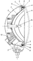
- FIG. 1 An embodiment according to the invention is shown in the drawing, which in a vertical middle section a headlight for vehicles shows that can be attached to the outside of the vehicle by means of a holder.
- the headlight has a pot-shaped housing made of plastic 2, in which an consisting of a reflector 3 and a lens 4 Light insert is used.
- the reflector 3 is bowl-shaped and is made of plastic.
- a retaining lug 12 is molded onto the reflector 3, which protrudes through an opening of the housing 2 and which is fixed with a outside of the vehicle attachable holder 1 is connected.
- the reflector 3 has an opening in the apex area for receiving a lamp 13.
- the End plate 4 is bowl-shaped and has on its outer Edge of a peripheral side wall 8 directed towards the housing 2.
- the Near its front edge, reflector 3 has a circumference on its rear side integrally formed side wall 9, which is directed radially outwards Inside at an equidistant distance from the inside of the side wall 8 of the lens 4 runs.
- the reflector 3 has on its front Edge on a radially outwardly directed edge portion 10, which together forms a circumferential receiving bed 5 with the side walls 8 and 9.
- the edge section 10 extends close to the inside of the side wall 8 and lies flat and all around on an annular platform 11, which is molded onto the inside of the lens 4.
- the admission bed 5 is U-shaped in cross section and takes one in cross section rectangular seal 7, which at the bottom of the receiving bed 5th and on the facing inner sides of the side walls 8 and 9 under tension is present.
- the seal 7 is made of soft rubber.
- an adhesive 6 is introduced in the remaining one Space of the receiving bed 5, which of the seal 7 and the Side walls 8 and 9 is limited. Even if a thin liquid adhesive is injected into the bed, this can until it hardens due to the seal not on the front inside flow of the lens.
- the seal 7 is the adhesive 6 receiving space of the bed 5 neatly delimited.
- the seal 7 can be used in different colors, making for the Headlights of different appearance variations are possible.
Landscapes
- Engineering & Computer Science (AREA)
- Mechanical Engineering (AREA)
- General Engineering & Computer Science (AREA)
- Lighting Device Outwards From Vehicle And Optical Signal (AREA)
- Non-Portable Lighting Devices Or Systems Thereof (AREA)
Abstract
Description
Claims (8)
- Scheinwerfer für Fahrzeuge, welcher außen am Fahrzeug mittels eines Halters (1) festsetzbar ist, mit einem in ein Gehäuse (2) eingesetzten Lichteinsatz, der einen Reflektor (3) und eine mit einem vorderen Randbereich des Reflektors (3) verklebte Abschlußscheibe (4) aufweist, die zusammen mit dem Reflektor (3) ein zum Gehäuse (2) hin geöffnetes umlaufendes Aufnahmebett (5) für einen Klebstoff (6) begrenzt, dadurch gekennzeichnet, daß zwischen dem Klebstoff (6) und dem Grund des Aufnahmebetts (5) umlaufend eine Dichtung (7) angeordnet ist, die angrenzend zu sich zugewandten Seitenwänden (8 und 9) des Aufnahmebetts (5) verläuft und für den Klebstoff (6) der Grund des Aufnahmebetts (5) ist.
- Scheinwerfer nach Anspruch 1, dadurch gekennzeichnet, daß die Dichtung (7) unter Vorspannung an den sich zugewandten Seitenwänden (8 und 9) des Aufnahmebetts (5) anliegt.
- Scheinwerfer nach Anspruch 1 oder 2, dadurch gekennzeichnet, daß die sich zugewandten Seitenwände (8 und 9) des Aufnahmebetts (5) mit ihren Innenseiten umlaufend in einem äquidistanten Abstand zueinander verlaufen.
- Scheinwerfer nach Anspruch 3, dadurch gekennzeichnet, daß das Aufnahmebett (5) in seinem Querschnitt U-förmig verläuft.
- Scheinwerfer nach Anspruch 4, dadurch gekennzeichnet, daß die Dichtung (7) im Querschnitt rechteckförmig gestaltet ist.
- Scheinwerfer nach einem der Ansprüche 2 bis 5, dadurch gekennzeichnet, daß eine Seitenwand (8) des Aufnahmebetts (5) von einem seitlichen Randabschnitt der Abschlußscheibe (4) gebidet ist, während die andere Seitenwand (9) zumindest abschnittsweise an die Rückseite des Reflektors (3) angebracht ist.
- Scheinwerfer nach einem der vorstehenden Ansprüche, dadurch gekennzeichnet, daß der Reflektor (3) an seinem vorderen Rand mit einem umlaufenden radialen Randabschnitt (10) das Aufnahmebett (5) an seinem Grund begrenzt und an einem Podest (1)1 der Innenseite der Abschlußscheibe (4) anliegt.
- Scheinwerfer nach einem der vorstehenden Ansprüche, dadurch gekennzeichnet, daß die Dichtung (7) aus Weichgummi besteht.
Applications Claiming Priority (2)
| Application Number | Priority Date | Filing Date | Title |
|---|---|---|---|
| DE19941523 | 1999-09-01 | ||
| DE19941523A DE19941523A1 (de) | 1999-09-01 | 1999-09-01 | Scheinwerfer für Fahrzeuge |
Publications (3)
| Publication Number | Publication Date |
|---|---|
| EP1081427A2 true EP1081427A2 (de) | 2001-03-07 |
| EP1081427A3 EP1081427A3 (de) | 2004-01-21 |
| EP1081427B1 EP1081427B1 (de) | 2006-07-26 |
Family
ID=7920337
Family Applications (1)
| Application Number | Title | Priority Date | Filing Date |
|---|---|---|---|
| EP00118703A Expired - Lifetime EP1081427B1 (de) | 1999-09-01 | 2000-08-30 | Scheinwerfer für Fahrzeuge |
Country Status (4)
| Country | Link |
|---|---|
| EP (1) | EP1081427B1 (de) |
| AT (1) | ATE334339T1 (de) |
| DE (2) | DE19941523A1 (de) |
| ES (1) | ES2269049T3 (de) |
Citations (1)
| Publication number | Priority date | Publication date | Assignee | Title |
|---|---|---|---|---|
| DE19728446C1 (de) | 1997-07-03 | 1999-01-28 | Hella Kg Hueck & Co | Kraftfahrzeugscheinwerfer mit einem Gehäuse und mit einer Befestigungsvorrichtung und ein Verfahren zum Zusammenbau eines solchen Kraftfahrzeugscheinwerfers |
Family Cites Families (2)
| Publication number | Priority date | Publication date | Assignee | Title |
|---|---|---|---|---|
| DE29604137U1 (de) * | 1996-03-06 | 1997-07-03 | Robert Bosch Gmbh, 70469 Stuttgart | Zusatzscheinwerfer für Fahrzeuge |
| DE29809618U1 (de) * | 1998-05-28 | 1998-07-30 | Hella Kg Hueck & Co | Scheinwerfer für Fahrzeuge, insbesondere Zusatzscheinwerfer für Kraftfahrzeuge |
-
1999
- 1999-09-01 DE DE19941523A patent/DE19941523A1/de not_active Withdrawn
-
2000
- 2000-08-30 AT AT00118703T patent/ATE334339T1/de not_active IP Right Cessation
- 2000-08-30 DE DE50013220T patent/DE50013220D1/de not_active Expired - Lifetime
- 2000-08-30 EP EP00118703A patent/EP1081427B1/de not_active Expired - Lifetime
- 2000-08-30 ES ES00118703T patent/ES2269049T3/es not_active Expired - Lifetime
Patent Citations (1)
| Publication number | Priority date | Publication date | Assignee | Title |
|---|---|---|---|---|
| DE19728446C1 (de) | 1997-07-03 | 1999-01-28 | Hella Kg Hueck & Co | Kraftfahrzeugscheinwerfer mit einem Gehäuse und mit einer Befestigungsvorrichtung und ein Verfahren zum Zusammenbau eines solchen Kraftfahrzeugscheinwerfers |
Also Published As
| Publication number | Publication date |
|---|---|
| ES2269049T3 (es) | 2007-04-01 |
| EP1081427A3 (de) | 2004-01-21 |
| DE19941523A1 (de) | 2001-03-08 |
| DE50013220D1 (de) | 2006-09-07 |
| ATE334339T1 (de) | 2006-08-15 |
| EP1081427B1 (de) | 2006-07-26 |
Similar Documents
| Publication | Publication Date | Title |
|---|---|---|
| DE3512882C2 (de) | ||
| DE29807774U1 (de) | Leuchte für Fahrzeuge, insbesondere Heckleuchte für Fahrzeuge | |
| DE1958761A1 (de) | Scheinwerfereinheit | |
| WO2005016107A1 (de) | Staubsauger mit einer gebläsekapsel | |
| DE19728446C1 (de) | Kraftfahrzeugscheinwerfer mit einem Gehäuse und mit einer Befestigungsvorrichtung und ein Verfahren zum Zusammenbau eines solchen Kraftfahrzeugscheinwerfers | |
| EP1081427B1 (de) | Scheinwerfer für Fahrzeuge | |
| DE4428438C1 (de) | Scheinwerfereinheit mit Abdeckteil für Kraftfahrzeuge | |
| DE20304930U1 (de) | Außenleuchte für Fahrzeuge | |
| DE3836032C2 (de) | Einkammerleuchte für Kraftfahrzeuge | |
| EP0945669A2 (de) | Scheinwerfer für Kraftfahrzeuge und Verfahren zur Herstellung eines Scheinwerfers | |
| DE3401437C2 (de) | Baugruppe eines Fahrzeug-Scheinwerfers | |
| DE8106289U1 (de) | Zierfelge fuer kraftfahrzeugfelgen | |
| DE4414899C1 (de) | Abdeckeinheit für ein Reflektoren aufnehmendes Gehäuse einer Lichteinheit für Kraftfahrzeuge | |
| DE4128534C1 (en) | Pivotable fixture for reflector of motor vehicle headlamp - provides pivotable point by pressed recess in outer housing edge serving as spring for groove in outer reflector edge | |
| DE102005035577A1 (de) | Beleuchtungseinrichtung für Fahrzeuge | |
| DE2217277C2 (de) | Glühlampenfassung, insbesondere für Kraftfahrzeug Scheinwerfer | |
| DE4445187A1 (de) | Scheinwerfer für Fahrzeuge | |
| DE69108473T2 (de) | Lampenanordnung. | |
| DE102013101024A1 (de) | Beleuchtungsvorrichtung für Fahrzeuge | |
| DE7321276U (de) | Trockenfilter, insbesondere für Kraftfahrzeuge | |
| DE8219688U1 (de) | Scheinwerfer fuer fahrzeuge, insbesondere leuchte fuer kraftfahrzeuge | |
| DE10254048B4 (de) | Scheinwerfer für Fahrzeuge | |
| DE1986511U (de) | Schweinwerfer fuer kraftfahrzeuge. | |
| DE2238739C3 (de) | Lichtsignalgeber für Verkehrssignalanlagen mit einer abklappbaren Frontplatte | |
| DE957923C (de) | Polarisierte Lichtquelle |
Legal Events
| Date | Code | Title | Description |
|---|---|---|---|
| PUAI | Public reference made under article 153(3) epc to a published international application that has entered the european phase |
Free format text: ORIGINAL CODE: 0009012 |
|
| AK | Designated contracting states |
Kind code of ref document: A2 Designated state(s): AT BE CH CY DE DK ES FI FR GB GR IE IT LI LU MC NL PT SE |
|
| AX | Request for extension of the european patent |
Free format text: AL;LT;LV;MK;RO;SI |
|
| RIN1 | Information on inventor provided before grant (corrected) |
Inventor name: NICKEL, HANS JUERGEN Inventor name: LEY, PETER Inventor name: KEMPER, ALBERT Inventor name: BRUMMEL, REINHOLD Inventor name: HACK, MICHAEL Inventor name: VON WUTHENAU, ALEXANDER Inventor name: WIESE, GERWIN Inventor name: MEYER, ERNST OTTO |
|
| PUAL | Search report despatched |
Free format text: ORIGINAL CODE: 0009013 |
|
| AK | Designated contracting states |
Kind code of ref document: A3 Designated state(s): AT BE CH CY DE DK ES FI FR GB GR IE IT LI LU MC NL PT SE |
|
| AX | Request for extension of the european patent |
Extension state: AL LT LV MK RO SI |
|
| RIC1 | Information provided on ipc code assigned before grant |
Ipc: 7F 21S 8/10 A Ipc: 7F 21V 31/00 B Ipc: 7F 21W 101/10 B Ipc: 7F 21V 17/00 B Ipc: 7B 60Q 1/04 B |
|
| 17P | Request for examination filed |
Effective date: 20040623 |
|
| AKX | Designation fees paid |
Designated state(s): AT BE CH CY DE DK ES FI FR GB GR IE IT LI LU MC NL PT SE |
|
| RAP1 | Party data changed (applicant data changed or rights of an application transferred) |
Owner name: HELLA KGAA HUECK & CO. |
|
| GRAP | Despatch of communication of intention to grant a patent |
Free format text: ORIGINAL CODE: EPIDOSNIGR1 |
|
| GRAS | Grant fee paid |
Free format text: ORIGINAL CODE: EPIDOSNIGR3 |
|
| GRAA | (expected) grant |
Free format text: ORIGINAL CODE: 0009210 |
|
| AK | Designated contracting states |
Kind code of ref document: B1 Designated state(s): AT BE CH CY DE DK ES FI FR GB GR IE IT LI LU MC NL PT SE |
|
| PG25 | Lapsed in a contracting state [announced via postgrant information from national office to epo] |
Ref country code: IE Free format text: LAPSE BECAUSE OF FAILURE TO SUBMIT A TRANSLATION OF THE DESCRIPTION OR TO PAY THE FEE WITHIN THE PRESCRIBED TIME-LIMIT Effective date: 20060726 Ref country code: FI Free format text: LAPSE BECAUSE OF FAILURE TO SUBMIT A TRANSLATION OF THE DESCRIPTION OR TO PAY THE FEE WITHIN THE PRESCRIBED TIME-LIMIT Effective date: 20060726 Ref country code: NL Free format text: LAPSE BECAUSE OF FAILURE TO SUBMIT A TRANSLATION OF THE DESCRIPTION OR TO PAY THE FEE WITHIN THE PRESCRIBED TIME-LIMIT Effective date: 20060726 |
|
| REG | Reference to a national code |
Ref country code: GB Ref legal event code: FG4D Free format text: NOT ENGLISH |
|
| REG | Reference to a national code |
Ref country code: CH Ref legal event code: EP |
|
| REG | Reference to a national code |
Ref country code: IE Ref legal event code: FG4D Free format text: LANGUAGE OF EP DOCUMENT: GERMAN |
|
| PG25 | Lapsed in a contracting state [announced via postgrant information from national office to epo] |
Ref country code: BE Free format text: LAPSE BECAUSE OF NON-PAYMENT OF DUE FEES Effective date: 20060831 Ref country code: LI Free format text: LAPSE BECAUSE OF NON-PAYMENT OF DUE FEES Effective date: 20060831 Ref country code: MC Free format text: LAPSE BECAUSE OF NON-PAYMENT OF DUE FEES Effective date: 20060831 Ref country code: CH Free format text: LAPSE BECAUSE OF NON-PAYMENT OF DUE FEES Effective date: 20060831 |
|
| REF | Corresponds to: |
Ref document number: 50013220 Country of ref document: DE Date of ref document: 20060907 Kind code of ref document: P |
|
| GBT | Gb: translation of ep patent filed (gb section 77(6)(a)/1977) |
Effective date: 20060913 |
|
| PG25 | Lapsed in a contracting state [announced via postgrant information from national office to epo] |
Ref country code: SE Free format text: LAPSE BECAUSE OF FAILURE TO SUBMIT A TRANSLATION OF THE DESCRIPTION OR TO PAY THE FEE WITHIN THE PRESCRIBED TIME-LIMIT Effective date: 20061026 Ref country code: DK Free format text: LAPSE BECAUSE OF FAILURE TO SUBMIT A TRANSLATION OF THE DESCRIPTION OR TO PAY THE FEE WITHIN THE PRESCRIBED TIME-LIMIT Effective date: 20061026 |
|
| PG25 | Lapsed in a contracting state [announced via postgrant information from national office to epo] |
Ref country code: PT Free format text: LAPSE BECAUSE OF FAILURE TO SUBMIT A TRANSLATION OF THE DESCRIPTION OR TO PAY THE FEE WITHIN THE PRESCRIBED TIME-LIMIT Effective date: 20061226 |
|
| NLV1 | Nl: lapsed or annulled due to failure to fulfill the requirements of art. 29p and 29m of the patents act | ||
| REG | Reference to a national code |
Ref country code: IE Ref legal event code: FD4D |
|
| ET | Fr: translation filed | ||
| REG | Reference to a national code |
Ref country code: ES Ref legal event code: FG2A Ref document number: 2269049 Country of ref document: ES Kind code of ref document: T3 |
|
| REG | Reference to a national code |
Ref country code: CH Ref legal event code: PL |
|
| PLBE | No opposition filed within time limit |
Free format text: ORIGINAL CODE: 0009261 |
|
| STAA | Information on the status of an ep patent application or granted ep patent |
Free format text: STATUS: NO OPPOSITION FILED WITHIN TIME LIMIT |
|
| 26N | No opposition filed |
Effective date: 20070427 |
|
| PG25 | Lapsed in a contracting state [announced via postgrant information from national office to epo] |
Ref country code: AT Free format text: LAPSE BECAUSE OF NON-PAYMENT OF DUE FEES Effective date: 20060830 |
|
| BERE | Be: lapsed |
Owner name: HELLA KGAA HUECK & CO. Effective date: 20060831 |
|
| PG25 | Lapsed in a contracting state [announced via postgrant information from national office to epo] |
Ref country code: GR Free format text: LAPSE BECAUSE OF FAILURE TO SUBMIT A TRANSLATION OF THE DESCRIPTION OR TO PAY THE FEE WITHIN THE PRESCRIBED TIME-LIMIT Effective date: 20061027 |
|
| PG25 | Lapsed in a contracting state [announced via postgrant information from national office to epo] |
Ref country code: LU Free format text: LAPSE BECAUSE OF NON-PAYMENT OF DUE FEES Effective date: 20060830 |
|
| PG25 | Lapsed in a contracting state [announced via postgrant information from national office to epo] |
Ref country code: CY Free format text: LAPSE BECAUSE OF FAILURE TO SUBMIT A TRANSLATION OF THE DESCRIPTION OR TO PAY THE FEE WITHIN THE PRESCRIBED TIME-LIMIT Effective date: 20060726 |
|
| PGFP | Annual fee paid to national office [announced via postgrant information from national office to epo] |
Ref country code: ES Payment date: 20090902 Year of fee payment: 10 Ref country code: FR Payment date: 20090814 Year of fee payment: 10 |
|
| PGFP | Annual fee paid to national office [announced via postgrant information from national office to epo] |
Ref country code: GB Payment date: 20090826 Year of fee payment: 10 |
|
| PGFP | Annual fee paid to national office [announced via postgrant information from national office to epo] |
Ref country code: IT Payment date: 20090819 Year of fee payment: 10 |
|
| GBPC | Gb: european patent ceased through non-payment of renewal fee |
Effective date: 20100830 |
|
| REG | Reference to a national code |
Ref country code: FR Ref legal event code: ST Effective date: 20110502 |
|
| PG25 | Lapsed in a contracting state [announced via postgrant information from national office to epo] |
Ref country code: IT Free format text: LAPSE BECAUSE OF NON-PAYMENT OF DUE FEES Effective date: 20100830 |
|
| PG25 | Lapsed in a contracting state [announced via postgrant information from national office to epo] |
Ref country code: FR Free format text: LAPSE BECAUSE OF NON-PAYMENT OF DUE FEES Effective date: 20100831 |
|
| PG25 | Lapsed in a contracting state [announced via postgrant information from national office to epo] |
Ref country code: GB Free format text: LAPSE BECAUSE OF NON-PAYMENT OF DUE FEES Effective date: 20100830 |
|
| REG | Reference to a national code |
Ref country code: ES Ref legal event code: FD2A Effective date: 20111019 |
|
| PG25 | Lapsed in a contracting state [announced via postgrant information from national office to epo] |
Ref country code: ES Free format text: LAPSE BECAUSE OF NON-PAYMENT OF DUE FEES Effective date: 20100831 |
|
| PGFP | Annual fee paid to national office [announced via postgrant information from national office to epo] |
Ref country code: DE Payment date: 20110824 Year of fee payment: 12 |
|
| PG25 | Lapsed in a contracting state [announced via postgrant information from national office to epo] |
Ref country code: DE Free format text: LAPSE BECAUSE OF NON-PAYMENT OF DUE FEES Effective date: 20130301 |
|
| REG | Reference to a national code |
Ref country code: DE Ref legal event code: R119 Ref document number: 50013220 Country of ref document: DE Effective date: 20130301 |