EP1081007A2 - Bremsdruckregelvorrichtung für Kraftfahrzeuge - Google Patents
Bremsdruckregelvorrichtung für Kraftfahrzeuge Download PDFInfo
- Publication number
- EP1081007A2 EP1081007A2 EP99308337A EP99308337A EP1081007A2 EP 1081007 A2 EP1081007 A2 EP 1081007A2 EP 99308337 A EP99308337 A EP 99308337A EP 99308337 A EP99308337 A EP 99308337A EP 1081007 A2 EP1081007 A2 EP 1081007A2
- Authority
- EP
- European Patent Office
- Prior art keywords
- pressure
- brake
- brake fluid
- hydraulic pump
- medium
- Prior art date
- Legal status (The legal status is an assumption and is not a legal conclusion. Google has not performed a legal analysis and makes no representation as to the accuracy of the status listed.)
- Granted
Links
- 239000012530 fluid Substances 0.000 claims abstract description 195
- 238000007599 discharging Methods 0.000 claims abstract description 16
- 230000003247 decreasing effect Effects 0.000 claims description 8
- 238000005086 pumping Methods 0.000 claims description 3
- 230000001965 increasing effect Effects 0.000 description 20
- 230000002708 enhancing effect Effects 0.000 description 3
- 230000007774 longterm Effects 0.000 description 2
- 238000004519 manufacturing process Methods 0.000 description 2
- 230000007423 decrease Effects 0.000 description 1
- 230000000881 depressing effect Effects 0.000 description 1
- 230000003467 diminishing effect Effects 0.000 description 1
Images


Classifications
-
- B—PERFORMING OPERATIONS; TRANSPORTING
- B60—VEHICLES IN GENERAL
- B60T—VEHICLE BRAKE CONTROL SYSTEMS OR PARTS THEREOF; BRAKE CONTROL SYSTEMS OR PARTS THEREOF, IN GENERAL; ARRANGEMENT OF BRAKING ELEMENTS ON VEHICLES IN GENERAL; PORTABLE DEVICES FOR PREVENTING UNWANTED MOVEMENT OF VEHICLES; VEHICLE MODIFICATIONS TO FACILITATE COOLING OF BRAKES
- B60T8/00—Arrangements for adjusting wheel-braking force to meet varying vehicular or ground-surface conditions, e.g. limiting or varying distribution of braking force
- B60T8/32—Arrangements for adjusting wheel-braking force to meet varying vehicular or ground-surface conditions, e.g. limiting or varying distribution of braking force responsive to a speed condition, e.g. acceleration or deceleration
- B60T8/34—Arrangements for adjusting wheel-braking force to meet varying vehicular or ground-surface conditions, e.g. limiting or varying distribution of braking force responsive to a speed condition, e.g. acceleration or deceleration having a fluid pressure regulator responsive to a speed condition
-
- B—PERFORMING OPERATIONS; TRANSPORTING
- B60—VEHICLES IN GENERAL
- B60T—VEHICLE BRAKE CONTROL SYSTEMS OR PARTS THEREOF; BRAKE CONTROL SYSTEMS OR PARTS THEREOF, IN GENERAL; ARRANGEMENT OF BRAKING ELEMENTS ON VEHICLES IN GENERAL; PORTABLE DEVICES FOR PREVENTING UNWANTED MOVEMENT OF VEHICLES; VEHICLE MODIFICATIONS TO FACILITATE COOLING OF BRAKES
- B60T8/00—Arrangements for adjusting wheel-braking force to meet varying vehicular or ground-surface conditions, e.g. limiting or varying distribution of braking force
- B60T8/24—Arrangements for adjusting wheel-braking force to meet varying vehicular or ground-surface conditions, e.g. limiting or varying distribution of braking force responsive to vehicle inclination or change of direction, e.g. negotiating bends
- B60T8/246—Change of direction
-
- B—PERFORMING OPERATIONS; TRANSPORTING
- B60—VEHICLES IN GENERAL
- B60T—VEHICLE BRAKE CONTROL SYSTEMS OR PARTS THEREOF; BRAKE CONTROL SYSTEMS OR PARTS THEREOF, IN GENERAL; ARRANGEMENT OF BRAKING ELEMENTS ON VEHICLES IN GENERAL; PORTABLE DEVICES FOR PREVENTING UNWANTED MOVEMENT OF VEHICLES; VEHICLE MODIFICATIONS TO FACILITATE COOLING OF BRAKES
- B60T8/00—Arrangements for adjusting wheel-braking force to meet varying vehicular or ground-surface conditions, e.g. limiting or varying distribution of braking force
- B60T8/32—Arrangements for adjusting wheel-braking force to meet varying vehicular or ground-surface conditions, e.g. limiting or varying distribution of braking force responsive to a speed condition, e.g. acceleration or deceleration
- B60T8/34—Arrangements for adjusting wheel-braking force to meet varying vehicular or ground-surface conditions, e.g. limiting or varying distribution of braking force responsive to a speed condition, e.g. acceleration or deceleration having a fluid pressure regulator responsive to a speed condition
- B60T8/48—Arrangements for adjusting wheel-braking force to meet varying vehicular or ground-surface conditions, e.g. limiting or varying distribution of braking force responsive to a speed condition, e.g. acceleration or deceleration having a fluid pressure regulator responsive to a speed condition connecting the brake actuator to an alternative or additional source of fluid pressure, e.g. traction control systems
- B60T8/4809—Traction control, stability control, using both the wheel brakes and other automatic braking systems
- B60T8/4827—Traction control, stability control, using both the wheel brakes and other automatic braking systems in hydraulic brake systems
- B60T8/4863—Traction control, stability control, using both the wheel brakes and other automatic braking systems in hydraulic brake systems closed systems
- B60T8/4872—Traction control, stability control, using both the wheel brakes and other automatic braking systems in hydraulic brake systems closed systems pump-back systems
- B60T8/4881—Traction control, stability control, using both the wheel brakes and other automatic braking systems in hydraulic brake systems closed systems pump-back systems having priming means
Definitions
- the present invention relates to a brake pressure control device and, more particularly, to a brake pressure control device for a vehicle which can provide a proper braking force for preventing slip of wheels during a braking or starting operation of a vehicle.
- the automobile is generally equipped with various system for improving its traveling stability, such as an anti-lock brake system(ABS), a brake traction control system(BTCS), and a vehicle dynamic control(VDC) system.
- ABS is a system for ensuring a stable braking capability by properly controlling the brake pressure when the vehicle is braked on a slippery road.
- BTCS brake traction control system
- VDC vehicle dynamic control
- the ABS is a system for ensuring a stable braking capability by properly controlling the brake pressure when the vehicle is braked on a slippery road.
- the BTCS is a system for preventing the wheels from slipping when the automobile is rapidly accelerated to start on a slippery road.
- VDC is a system for enhancing a traveling stability by applying proper brake pressure to the wheels, specially when the driver can not drive the vehicle at driver's will by the external force during driving the vehicle at high speed.
- Such a brake pressure control device for a vehicle is disclosed in Japanese laid-open utility model No. 4-116274. This will be described hereinafter with reference to Fig. 1.
- the conventional brake pressure control device for a vehicle comprises wheel cylinders 10a, 10b, 10c and 10d mounted on front wheels FR and FL and rear wheels RR and RL, a brake pedal 1 operated by a driver, a booster 2 for generating large braking force by cooperating with the pedal 1, a fluid tank 4 for storing fluid, and a master cylinder 3 which receives boosted force from the booster 2 to generate brake pressure using the fluid stored in the fluid tank 4 and then transmits brake pressure to the wheel cylinders 10a, 10b, 10c and 10d.
- normal open solenoid inflow-valves 5a, 5b and 5c are disposed on fluid paths through which the brake pressure is applied to the wheel cylinders 10a, 10b, 10c and 10d from the master cylinder 3
- normal close solenoid outflow-valves 6a, 6b and 6c are disposed on fluid paths through which the brake pressure discharged from the wheel cylinders 10a, 10b, 10c and 10d is returned to the master cylinder 3 or the normal open solenoid inflow-valves 5a, 5b and 5c.
- low-pressure accumulators 7a and 7b Disposed on each downstream side of the normal close solenoid outflow-valves 6a, 6b and 6c are low-pressure accumulators 7a and 7b for temporally storing brake fluid discharged from each of the wheel cylinders 10a, 10b, 10c and 10d, a hydraulic pumps 8a and 8b for ABS, and a motor 9 for driving the hydraulic pumps 8a and 8b.
- ECU - not shown an electronic control unit which analyzes the wheel velocity detected by a wheel speed sensor (not shown) and controls the operation of the brake system according to the results of analysis.
- a first normal open solenoid valve 11 is disposed on a fluid path 21 connecting a discharging port of the hydraulic pump 8b of the rear wheel RR and RL sides to an outlet side of the master cylinder 3.
- the valve 11 is maintained open in a normal state, and is closed by the ECU when at the beginning of BTCS or VDC operation.
- the hydraulic pump 13 for BTCS or VDC is provided additionally besides the hydraulic pumps 8a and 8b for ABS.
- the brake fluid pressure in the accumulator 14 should be always maintained above a certain level by the hydraulic pump 13, the large-sized hydraulic pump 13 and the high-pressure accumulator 14 are necessarily required, thus a brake pressure control device becomes large and heavy, and manufacturing cost is increased.
- the present invention provides a brake pressure control device for a vehicle, comprising a master cylinder for forming brake pressure using fluid, a wheel cylinder exerting braking force to each wheel of the vehicle by receiving the brake pressure, a normal open solenoid inflow-valve disposed on an inlet side of the wheel cylinder for controlling flow of the brake fluid pressure, a normal close solenoid outflow-valve disposed on an outlet side of the wheel cylinder for controlling flow of the brake fluid pressure, a hydraulic pump for pumping the brake fluid pressure to the wheel cylinder, an electronic control unit for controlling flow of the brake fluid pressure applied to the wheel cylinder, a first normal open solenoid valve disposed on a first fluid path connecting a discharging port of the hydraulic pump to an outlet side of the master cylinder to direct the brake fluid pressure discharged from the master cylinder to the wheel cylinder via the inflow-valve when braking operation is executed, a normal open electric shuttle valve disposed on a fluid path connecting the outlet side of the master cylinder to a suction
- the brake pressure control device further comprises a second fluid path connecting the discharging port of the hydraulic pump to the outlet side of the master cylinder additionally, a first relief valve disposed on the second fluid path to direct the brake fluid discharged from the hydraulic pump to the master cylinder when the brake fluid pressure increases above a certain level during brake traction control system or vehicle dynamic control operation, a second relief valve disposed on the bypass fluid path between the discharging port of the hydraulic pump and the medium-pressure accumulator to direct the brake fluid discharged from the hydraulic pump to the medium-pressure accumulator when the brake fluid pressure increases above a certain level during brake traction control system or vehicle dynamic control operation, and a fluid detecting sensor installed in the medium-pressure accumulator.
- the electric control unit closes the normal open solenoid inflow-valve and the first normal open solenoid valve to cut off the communication of the master cylinder with the wheel cylinder, and drives the hydraulic pump so as to suck the brake fluid within the master cylinder via the electric shuttle valve and discharge, thereby the brake fluid pressure being directed to the medium-pressure accumulator via the second relief valve.
- the electric control unit closes the normal open solenoid inflow-valve and the first normal open solenoid valve to cut off the communication of the master cylinder with the wheel cylinder, and drives the hydraulic pump so as to suck the brake fluid within the master cylinder via the electric shuttle valve and discharge, thereby the brake fluid being directed to the medium-pressure accumulator via the second relief valve.
- the electric control unit counts the time and drives the hydraulic pump by periods set to the ECU so as to store the brake fluid in the medium-pressure accumulator repeatedly.
- the electric control unit If the brake pressure control operation such as anti-lock brake system or brake traction control system or vehicle dynamic control is executed before it reaches the setting period, the electric control unit resets the time counted before and recounts the time after the brake pressure control operation is finished.
- the hydraulic pump is driven continuously during anti-lock brake system or brake traction control system or vehicle dynamic control operation.
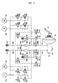
- Fig. 2 is a schematic view illustrating a brake pressure control device for a vehicle associated with a hydraulic circuit thereof according to a preferred embodiment of the present invention.
- the brake pressure control device for a vehicle comprises wheel cylinders 70a, 70b, 70c and 70d mounted on front wheels FR and FL and rear wheels RR and RL, a brake pedal 51 operated by a driver, a booster 52 for generating large braking force by cooperating with the pedal 51, a fluid tank 54 for storing fluid, and a master cylinder 53 which receives boosted force from the booster 52 to generate brake pressure using the fluid stored in the fluid tank 54 and then transmits brake pressure to the wheel cylinders 70a, 70b, 70c and 70d.
- normal open solenoid inflow-valves 55a, 55b, 55c and 55d are disposed on fluid paths through which the brake pressure is applied to the wheel cylinders 70a, 70b, 70c and 70d from the master cylinder 53
- normal close solenoid outflow-valves 56a, 56b, 56c and 56d are disposed on fluid paths through which the brake pressure discharged from the wheel cylinders 70a, 70b, 70c and 70d is returned to the master cylinder 53 or the normal open solenoid inflow-valves 55a, 55b, 55c and 55d.
- low-pressure accumulators 57a and 57b for temporally storing brake fluid discharged from the wheel cylinders 70a, 70b, 70c and 70d
- a hydraulic pumps 58a and 58b for ABS which pump the brake fluid within the low-pressure accumulators 57a and 57b to return forcedly to the master cylinder 53 or the inflow-valves 55a, 55b, 55c and 55d
- a motor 59 for driving the hydraulic pumps 58a and 58b
- high-pressure accumulators 60a and 60b and orifices 61a and 61b for reducing a radical wave of the brake fluid pressure pumped by the hydraulic pumps 58a and 58b.
- an electronic control unit(ECU) which analyzes the wheel velocity detected by a wheel speed sensor (not shown) and controls the operation of the brake system according to the results of analysis.
- First normal open solenoid valves 62a and 62b are disposed respectively on first fluid paths 71a and 71b which connect discharging ports of the hydraulic pumps 58a and 58b to an outlet side of the master cylinder 53.
- the first solenoid valves 62a and 62b are maintained open in a normal state so that the brake fluid discharged from the master cylinder 53 can be fed to the wheel cylinders 70a, 70b, 70c and 70d through the inflow-valves 55a, 55b, 55c and 55d, while the first solenoid valves 62a and 62b are closed by the ECU when at the beginning of BTCS or VDC operation, which will be described in detail later.
- first relief valves 63a and 63b are disposed respectively on second fluid paths 72a and 72b which connect the discharging ports of the hydraulic pumps 58a and 58b to the outlet side of the master cylinder 53 additionally.
- the brake fluid pressure discharged from the hydraulic pumps 58a and 58b increases above a certain level during BTCS or VDC operation, the brake fluid is returned to the master cylinder 53 through the first relief valves 63a and 63b.
- third fluid paths 73a and 73b Disposed on third fluid paths 73a and 73b which connect the outlet side of the master cylinder 53 to the suction ports of the hydraulic pumps 58a and 58b, are normal open electric shuttle valves 64a and 64b, which will be described later.
- the brake pressure control device for a vehicle further includes bypass fluid paths 74a and 74b for bypassing the brake fluid discharged from the discharging ports of the hydraulic pumps 58a and 58b to the suction ports thereof. Disposed on the bypass fluid paths 74a and 74b are medium-pressure accumulators 66a and 66b in which the brake fluid pressure is stored at a certain level.
- Second normal close solenoid valves 67a and 67b Disposed on the bypass fluid paths 74a and 74b between the medium-pressure accumulators 66a and 66b and the suction ports of the hydraulic pumps 58a and 58 are second normal close solenoid valves 67a and 67b which maintain the brake fluid pressure stored in the medium-pressure accumulators 66a and 66b, the valves 67a and 67b being opened to communicate the medium-pressure accumulators 66a and 66b with the suction ports of the hydraulic pumps 58a and 58b during BTCS or VDC operation.
- second relief valves 65a and 65b for directing the brake fluid discharged from the hydraulic pumps 58a and 58b to the medium-pressure accumulators 66a and 66b when the brake fluid pressure increases above a certain level during BTCS or VDC operation.
- a fluid detecting sensor (not shown) is installed in the medium-pressure accumulators 66a and 66b, which will be described later.
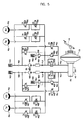
- Fig. 3 is a hydraulic circuit illustrating a normal braking operation state of a brake pressure control device for a vehicle according to the present invention.
- the brake fluid pressure is generated by the master cylinder 53, and the first normal open solenoid valves 62a and 62b and the normal open electric shuttle valves 64a and 64b are maintained open.
- the brake fluid pressure is fed to the suction ports of the hydraulic pumps 58a and 58b via the shuttle valves 64a and 64b, while the brake fluid pressure is also fed to the high-pressure accumulators 60a and 60b disposed on the discharging ports of the pumps 58a and 58b via the first solenoid valves 62a and 62b, so the flow of the brake fluid through the pumps 58a and 58b is prevented.
- the brake fluid passed through the shuttle valves 64a and 64b is prevented from being fed to the low-pressure accumulators 57a and 57b by check valves 68a and 68b, so the flow of the brake fluid through the third fluid paths 73a and 73b is prevented. Accordingly, the brake fluid pressure generated from the master cylinder 53 is supplied to the wheel cylinders 70a, 70b, 70c and 70d via the first normal open solenoid valves 62a and 62b and the normal open solenoid inflow-valves 55a, 55b, 55c and 55d to execute a brake function.
- the brake fluid within the wheel cylinders 70a, 70b, 70c and 70d is returned to the master cylinder 53.
- the ant-lock brake system should be properly controlled in three modes(a pressure increasing mode, a pressure reducing mode, and a pressure unchanging mode) to prevent the above problems. This will be described more in detail hereinafter.
- Fig. 4 is a hydraulic circuit illustrating a pressure reducing mode of a brake pressure control device for a vehicle according to the present invention during ABS operation.
- the ECU closes the electric shuttle valves 64a and 64b and the normal open solenoid inflow-valves 55a, 55b, 55c and 55d disposed on each inlet side of the wheel cylinders 70a, 70b, 70c and 70d to cut off the communication of the master cylinder 53 with the wheel cylinders 70a, 70b, 70c and 70d.
- the ECU opens the normal close solenoid outflow-valves 56a, 56b, 56c and 56d disposed on each outlet side of the wheel cylinders 70a, 70b, 70c and 70d to direct the brake fluid within the wheel cylinders 70a, 70b, 70c and 70d to the hydraulic pumps 58a and 58b, thereby reducing the brake fluid pressure applied to the wheel cylinders 70a, 70b, 70c and 70d to prevent the wheels FR, RL, RR and FL of the vehicle from sliding.
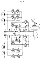
- Fig. 5 is a hydraulic circuit illustrating a pressure increasing mode of a brake pressure control device for a vehicle according to the present invention during ABS operation.
- the ECU closes the electric shuttle valves 64a and 64b, while opens the normal open solenoid inflow-valves 55a, 55b, 55c and 55d disposed on each inlet side of the wheel cylinders 70a, 70b, 70c and 70d.
- the ECU drives the motor 59 and the hydraulic pumps 58a and 58b for pumping the brake fluid fed to the hydraulic pumps 58a and 58b from the wheel cylinders 70a, 70b, 70c and 70d during the pressure reducing mode.
- the brake fluid pumped from the hydraulic pumps 58a and 58b receives pressure having a pulse wave, but changes into linear hydraulic pressure while passing through the high-pressure accumulators 60a and 60b and the orifices 61a and 61b.
- the linear hydraulic pressure is supplied to the wheel cylinders 70a, 70b, 70c and 70d via the normal open solenoid inflow-valves 55a, 55b, 55c and 55d, thereby increasing the braking force.
- the normal close solenoid outflow-valves 56a, 56b, 56c and 56d disposed on each outlet side of the wheel cylinders 70a, 70b, 70c and 70d are closed preferentially by the ECU.
- the brake fluid pressure applied to the wheel cylinders 70a, 70b, 70c and 70d reaches an optimal level at which optimal braking force is generated, the pressure should not be changed, that is, the brake fluid pressure should be maintained.
- Fig. 6 is a hydraulic circuit illustrating a pressure unchanging mode of a brake pressure control device for a vehicle according to the present invention during ABS operation.
- the ECU closes the electric shuttle valves 64a and 64b and the normal open solenoid inflow-valves 55a, 55b, 55c and 55d disposed on each inlet side of the wheel cylinders 70a, 70b, 70c and 70d to block the brake fluid being fed to the wheel cylinders 70a, 70b, 70c and 70d.
- a brake traction control system(BTCS) is operated to provide adequate braking force to the wheels FR, RL, RR and FL by increasing or decreasing the driving force or reducing the engine power without depressing the brake pedal 51.
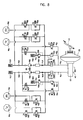
- Fig. 7 is a hydraulic circuit illustrating a pressure applying mode of a brake pressure control device for a vehicle according to the present invention during BTCS operation.
- the ECU starts BTCS operation when it detects the slip of the driving wheels RL and RR. Accordingly, the ECU closes the first normal open solenoid valves 62a and 62b and the shuttle valves 64a and 64b to cut off the communication of the master cylinder 53 with the wheel cylinders 70a, 70b, 70c and 70d, while opens the second normal close solenoid valves 67a and 67b connected to the medium-pressure accumulators 66a and 66b to communicate the medium-pressure accumulators 66a and 66b with the suction ports of the hydraulic pumps 58a and 58b.
- the hydraulic pumps 58a and 58b are driven, so that the brake fluid pressure stored in the medium-pressure accumulators 66a and 66b changes into linear hydraulic pressure while passing through the high-pressure accumulators 60a and 60b and the orifices 61a and 61b and is fed to the wheel cylinders 70b and 70c of the driving wheels RL and RR via the normal open solenoid inflow-valves 55b and 55c, thereby increasing the braking force and diminishing the slip of the driving wheels RL and RR.
- the ECU closes the normal open solenoid inflow-valves 55a and 55d of the driven wheels FR and FL so that the braking force is not transmitted to the wheel cylinders 70a and 70d of the driven wheels FR and FL.
- Fig. 8 is a hydraulic circuit illustrating a pressure decreasing mode of a brake pressure control device for a vehicle according to the present invention during BTCS operation.
- the brake fluid pressure applied to the wheel cylinders 70b and 70c of the driving wheels RL and RR should be decreased at an optimal level.
- the ECU closes all normal open solenoid inflow-valves 55a, 55b, 55c and 55d disposed on each inlet side of the wheel cylinders 70a, 70b, 70c and 70d in the state of closing the electric shuttle valves 64a and 64b, while opens the normal close solenoid outflow-valves 56b and 56c disposed on each outlet side of the wheel cylinders 70b and 70c of the driving wheels RL and RR, so that the brake fluid within the wheel cylinders 70b and 70c flows to the suction port of the hydraulic pumps 58a and 58b, thereby the braking force applied to the wheel cylinders 70b and 70c being reduced and the driving wheels RL and RR being accelerated.
- the brake fluid pressure applied to the wheel cylinders 70b and 70c of the driving wheels RL and RR reaches an optimal level at which optimal braking force is generated, the brake fluid pressure should not be changed, that is, the brake fluid pressure should be maintained.
- Fig. 9 is a hydraulic circuit illustrating a pressure unchanging mode of a brake pressure control device for a vehicle according to the present invention during BTCS operation.
- the ECU closes the normal open solenoid inflow-valves 55b and 55c disposed on each inlet side of the wheel cylinders 70b and 70c in the state of closing the electric shuttle valves 64a and 64b, so that the brake fluid pressure generated from the hydraulic pumps 58a and 58b can not be fed to the wheel cylinders 70b and 70c any more.
- the driving wheels RL and RR are controlled independently, there may be a wheel cylinder which requires unchanged brake pressure, or increased brake pressure, or reduced brake pressure.
- the motor 59 should be driven continuously during BTCS operation, thereby the brake fluid pressure being generated continuously from the hydraulic pumps 58a and 58b.
- the brake fluid pressure discharged from the hydraulic pumps 58a and 58b increases above a certain level, the brake fluid is stored in the medium-pressure accumulators 66a and 66b via the second relief valves 65a and 65b disposed on the bypass fluid paths 74a and 74b, or is returned to the master cylinder 53 via the first relief valves 64a and 64b disposed on the second fluid paths 72a and 72b.
- VDC vehicle dynamic control
- the reference angle value at which the driver can turn the steering wheel with reference to the current velocity of the vehicle, is inputted to the ECU in advance. If the driver turns the steering wheel to right or left more than the reference angle value, a so-called over-steering phenomenon of that the car tends to incline to inside of the cornering direction and be spined in the worst case may happen. And, if the car corners on a slippery road, a so-called under-steering phenomenon of that the car tends to incline to outside of the cornering direction may happen.
- the ECU applies the brake fluid pressure to the outer wheels of the cornering direction of the vehicle in the over-steering condition, while the ECU applies the brake fluid pressure to the inner wheels in the under-steering condition, thereby enhancing a traveling stability, which will be described more in detail with reference to Fig. 10.
- Fig. 10 is a hydraulic circuit illustrating VDC operation of a brake pressure control device for a vehicle according to the present invention. It is supposed that RL and FL are inner wheels of the cornering direction of the vehicle and FR and RR are outer wheels.
- the ECU closes the first normal open solenoid valves 62a and 62b and the electric shuttle valves 64a and 64b to cut off the communication of the master cylinder 53 with the wheel cylinders 70a, 70b, 70c and 70d, while opens the second normal close solenoid valves 67a and 67b connected to the medium-pressure accumulators 66a and 66b to communicate the medium-pressure accumulators 66a and 66b with each suction port of the hydraulic pumps 58a and 58b.
- the hydraulic pumps 58a and 58b are driven, so that the brake fluid pressure stored in the medium-pressure accumulators 66a and 66b changes into linear hydraulic pressure while passing through the high-pressure accumulators 60a and 60b and the orifices 61a and 61b and is fed to the wheel cylinders 70a, 70b, 70c and 70d via the normal open solenoid inflow-valves 55a, 55b, 55c and 55d.
- the ECU closes the normal open solenoid inflow-valves 55b and 55d of the inner wheels RL and FL of the cornering direction so that the brake fluid pressure is prevented from being applied to the corresponding wheel cylinders 70b and 70d, while maintains to open the inflow-valves 55a and 55c of the outer wheels FR and RR so that the brake fluid pressure is applied to the corresponding wheel cylinders 70a and 70c.
- a turning moment which acts opposite to the cornering direction of the vehicle generates on the outer wheels FR and RR, thereby preventing the vehicle from inclining to inside of the cornering direction and being spined.
- the ECU applies the brake fluid pressure to only wheel cylinders 70b and 70d of the inner wheels RL and FL, contrary to the over-steering condition, so that a turning moment generating on the inner wheels RL and FL enables the vehicle to travel stably. Since VDC operation in the under-steering condition is similar to that of the over-steering condition, the detail description is omitted.
- the motor 59 is driven continuously during VDC operation, thereby the brake fluid pressure being generated continuously from the hydraulic pumps 58a and 58b.
- the brake fluid is stored in the medium-pressure accumulators 66a and 66b via the second relief valves 65a and 65b disposed on the bypass fluid paths 74a and 74b, or is returned to the master cylinder 53 via the first relief valves 64a and 64b disposed on the second fluid paths 72a and 72b.
- the brake pressure control device for a vehicle there is no need to control the hydraulic pumps 58a and 58b according to respective mode(a pressure increasing mode, a pressure reducing mode, and a pressure unchanging mode) of ABS, or BTCS, or VDC. That is, although the motor 59 is driven continuously during ABS, or BTCS, or VDC operation, the brake fluid pressure increased above a certain level is stored in the medium-pressure accumulators 66a and 66b via the second relief valves 65a and 65b or is returned to the master cylinder 53 via the first relief valves 64a and 64b, thus the control of the hydraulic pumps 58a and 58b is considerably simple.
- Fig. 11 is a hydraulic circuit illustrating an operation of storing brake fluid pressure in a medium-pressure accumulator of a brake pressure control device for a vehicle according to the present invention.
- a fluid detecting sensor (not shown) is installed in the medium-pressure accumulators 66a and 66b. If the brake fluid existing within the medium-pressure accumulators 66a and 66b is detected to be decreased below a certain level by the fluid detecting sensor, the ECU closes the normal open solenoid inflow-valves 55a, 55b, 55c and 55d and the first normal open solenoid valves 62a and 62b to cut off the communication of the master cylinder 53 with the wheel cylinders 70a, 70b, 70c and 70d, and at the same time, drives the hydraulic pumps 58a and 58b so as to suck the brake fluid within the master cylinder 53 via the electric shuttle valves 64a and 64b disposed on the third fluid paths 73a and 73b and discharge.
- the brake fluid pressure can be stored in the medium-pressure accumulators 66a and 66b without the fluid detecting sensor, which will be described hereinafter.
- the brake fluid pressure is continuously stored in the medium-pressure accumulators 66a and 66b during the brake pressure control operation such as ABS or BTCS or VDC.
- the brake fluid existing within the accumulators 66a and 66b may leak through the second relief valves 65a and 65b and the second normal close solenoid valves 67a and 67b, as described above.
- the ECU closes the normal open solenoid inflow-valves 55a, 55b, 55c and 55d and the first normal open solenoid valves 62a and 62b to cut off the communication of the master cylinder 53 with the wheel cylinders 70a, 70b, 70c and 70d, and drives the hydraulic pumps 58a and 58b so as to suck the brake fluid within the master cylinder 53 via the electric shuttle valves 64a and 64b and discharge, thereby the brake fluid being directed to the medium-pressure accumulators 66a and 66b via the second relief valves 65a and 65b.
- the ECU counts the time and drives the hydraulic pumps 58a and 58b by periods set to the ECU so as to store the brake fluid in the medium-pressure accumulators 66a and 66b repeatedly. It is preferable that the above storing operation is executed for 1 second per 4 hours considering the brake fluid leakage through the second relief valves 65a and 65b and the second solenoid valves 67a and 67b.
- the brake pressure control operation such as ABS or BTCS or VDC
- the brake fluid pressure is stored in the medium-pressure accumulators 66a and 66b, as described above. Therefore, the ECU resets the time counted before and recounts the time after the brake pressure control operation is finished until it reaches the setting period for performing the storing operation.
- the brake fluid discharged from the hydraulic pumps 58a and 58b is returned to the master cylinder 53 via the first relief valves 63a and 63b, thus the brake pressure control device is prevented from being affected by the excessively increased brake fluid pressure.
- the brake pressure control device for a vehicle As described above in detail, in the brake pressure control device for a vehicle according to the present invention, during BTCS or VDC operation, since brake fluid having a prescribed pressure is transmitted to a hydraulic pump for ABS from a medium-pressure accumulator, the efficiency of the pump is improved and the increasing velocity of brake fluid pressure becomes higher, thereby applying the required brake fluid pressure to each wheel cylinder more rapidly so as to control the traveling unstability of a vehicle effectively in its early stages.
- this invention has further advantages in that since the conventional large-sized accumulator and additional hydraulic pump are needless and a relatively small-sized hydraulic pump for ABS can be used in BTCS or VDC operation, the brake pressure control device of this invention becomes light and small-sized, and manufacturing cost is reduced.
Landscapes
- Engineering & Computer Science (AREA)
- Physics & Mathematics (AREA)
- Fluid Mechanics (AREA)
- Transportation (AREA)
- Mechanical Engineering (AREA)
- Regulating Braking Force (AREA)
- Valves And Accessory Devices For Braking Systems (AREA)
Applications Claiming Priority (2)
| Application Number | Priority Date | Filing Date | Title |
|---|---|---|---|
| KR9934881 | 1999-08-23 | ||
| KR1019990034881A KR100313701B1 (ko) | 1999-08-23 | 1999-08-23 | 브레이크액압 제어장치 |
Publications (3)
| Publication Number | Publication Date |
|---|---|
| EP1081007A2 true EP1081007A2 (de) | 2001-03-07 |
| EP1081007A3 EP1081007A3 (de) | 2003-06-18 |
| EP1081007B1 EP1081007B1 (de) | 2007-08-08 |
Family
ID=19608242
Family Applications (1)
| Application Number | Title | Priority Date | Filing Date |
|---|---|---|---|
| EP99308337A Expired - Lifetime EP1081007B1 (de) | 1999-08-23 | 1999-10-21 | Bremsdruckregelvorrichtung für Kraftfahrzeuge |
Country Status (3)
| Country | Link |
|---|---|
| EP (1) | EP1081007B1 (de) |
| KR (1) | KR100313701B1 (de) |
| DE (1) | DE69936775D1 (de) |
Cited By (5)
| Publication number | Priority date | Publication date | Assignee | Title |
|---|---|---|---|---|
| EP1334894A3 (de) * | 2002-02-01 | 2004-01-02 | Mando Corporation | Elektronisch gesteuertes Bremssystem für Kraftfahrzeuge |
| WO2007012562A1 (de) * | 2005-07-29 | 2007-02-01 | Robert Bosch Gmbh | Fahrzeugbremsanlage mit einer pumpe |
| EP1749721A1 (de) * | 2005-08-01 | 2007-02-07 | Robert Bosch Gmbh | Verfahren und Vorrichtung zur Ansteuerung einer Bremsanlage |
| CN102039888A (zh) * | 2009-09-29 | 2011-05-04 | 株式会社万都 | 用于电子控制制动系统的泵单元 |
| CN113442892A (zh) * | 2020-03-26 | 2021-09-28 | 比亚迪股份有限公司 | 失效辅助制动装置、液压制动系统和车辆 |
Families Citing this family (6)
| Publication number | Priority date | Publication date | Assignee | Title |
|---|---|---|---|---|
| KR20010045754A (ko) * | 1999-11-08 | 2001-06-05 | 밍 루 | 차량의 브레이크액압 제어방법 |
| KR100372240B1 (ko) * | 1999-11-09 | 2003-02-17 | 주식회사 만도 | 중압 어큐뮬레이터를 구비한 브레이크 액압 제어장치 |
| KR100413320B1 (ko) * | 2000-04-20 | 2003-12-31 | 주식회사 만도 | 브레이크 액압제어장치 |
| KR20030026012A (ko) * | 2001-09-24 | 2003-03-31 | 주식회사 만도 | 차량용 브레이크 트랙션 콘트롤 시스템 |
| KR100845918B1 (ko) * | 2002-02-09 | 2008-07-11 | 주식회사 만도 | 브레이크 액압 제어장치 |
| KR101761553B1 (ko) | 2015-09-10 | 2017-07-26 | 이파워텍(주) | 그레이팅 커버 |
Family Cites Families (6)
| Publication number | Priority date | Publication date | Assignee | Title |
|---|---|---|---|---|
| DE4213199A1 (de) * | 1992-04-22 | 1993-10-28 | Teves Gmbh Alfred | Hydraulische Bremsanlage mit Bremsschlupf- und Antriebsschlupfregelung |
| DE4220835A1 (de) * | 1992-06-25 | 1994-01-05 | Teves Gmbh Alfred | Schlupfgeregelte hydraulische Bremsanlage |
| DE4333568A1 (de) * | 1993-10-01 | 1995-04-06 | Teves Gmbh Alfred | Bremsanlage für Kraftfahrzeuge mit einer Einrichtung zum Regeln sowohl des Brems- als auch des Antriebsschlupfes |
| DE19537927A1 (de) * | 1995-10-12 | 1997-04-17 | Teves Gmbh Alfred | Verfahren zum Betrieb einer hydraulischen Bremsanlage |
| AU5701198A (en) * | 1996-12-13 | 1998-07-03 | Kelsey-Hayes Company | Vehicular brake system with vehicle stability management |
| DE19806724B4 (de) * | 1998-02-18 | 2005-02-17 | Continental Teves Ag & Co. Ohg | Bremsanlage mit Pulsationsdämpfer |
-
1999
- 1999-08-23 KR KR1019990034881A patent/KR100313701B1/ko not_active Expired - Fee Related
- 1999-10-21 DE DE69936775T patent/DE69936775D1/de not_active Expired - Lifetime
- 1999-10-21 EP EP99308337A patent/EP1081007B1/de not_active Expired - Lifetime
Cited By (5)
| Publication number | Priority date | Publication date | Assignee | Title |
|---|---|---|---|---|
| EP1334894A3 (de) * | 2002-02-01 | 2004-01-02 | Mando Corporation | Elektronisch gesteuertes Bremssystem für Kraftfahrzeuge |
| WO2007012562A1 (de) * | 2005-07-29 | 2007-02-01 | Robert Bosch Gmbh | Fahrzeugbremsanlage mit einer pumpe |
| EP1749721A1 (de) * | 2005-08-01 | 2007-02-07 | Robert Bosch Gmbh | Verfahren und Vorrichtung zur Ansteuerung einer Bremsanlage |
| CN102039888A (zh) * | 2009-09-29 | 2011-05-04 | 株式会社万都 | 用于电子控制制动系统的泵单元 |
| CN113442892A (zh) * | 2020-03-26 | 2021-09-28 | 比亚迪股份有限公司 | 失效辅助制动装置、液压制动系统和车辆 |
Also Published As
| Publication number | Publication date |
|---|---|
| DE69936775D1 (de) | 2007-09-20 |
| EP1081007B1 (de) | 2007-08-08 |
| KR20010018781A (ko) | 2001-03-15 |
| KR100313701B1 (ko) | 2001-11-15 |
| EP1081007A3 (de) | 2003-06-18 |
Similar Documents
| Publication | Publication Date | Title |
|---|---|---|
| JP3716215B2 (ja) | 車両用電子制御式ブレーキシステム | |
| JP2602794B2 (ja) | 路上走行車両用の流体圧制御二系統ブレーキ・システム | |
| KR100482959B1 (ko) | 차량용 전자제어식 브레이크 시스템 | |
| EP1081007B1 (de) | Bremsdruckregelvorrichtung für Kraftfahrzeuge | |
| US12370989B2 (en) | Electro-hydraulic brake device | |
| JPH0516779A (ja) | 車両用アンチロツクブレーキおよびトラクシヨンコントロールシステム用油圧モジユレータ | |
| JPH10250556A (ja) | ブレーキ制御装置 | |
| GB2311575A (en) | A vehicle brake system with anti-lock, traction, and stability control | |
| JP2002067917A (ja) | 車両用制動制御装置 | |
| US6024424A (en) | Braking device | |
| US5882091A (en) | Brake pressure control apparatus | |
| JP3870480B2 (ja) | 車両用ブレーキ装置 | |
| JP3580459B2 (ja) | ブレーキシステム | |
| JP4484986B2 (ja) | ブレーキ液圧源装置およびブレーキ装置 | |
| JPH11301443A (ja) | 車両用2系統液圧ブレーキ装置 | |
| KR100774116B1 (ko) | 브레이크 액압 제어장치 | |
| KR100845918B1 (ko) | 브레이크 액압 제어장치 | |
| JP2004217131A (ja) | 制動システム | |
| JP2009208697A (ja) | 車輌制御装置 | |
| JP2592152Y2 (ja) | 車両用ブレーキ液圧制御装置 | |
| JPH11227587A (ja) | ブレーキ装置 | |
| KR200296168Y1 (ko) | 차량용안티록브레이크시스템 | |
| JP2003154931A (ja) | ブレーキ液圧制御装置 | |
| JP2002046591A (ja) | ブレーキ制御装置 | |
| JPH03258644A (ja) | 車両用液圧ブレーキ装置 |
Legal Events
| Date | Code | Title | Description |
|---|---|---|---|
| PUAI | Public reference made under article 153(3) epc to a published international application that has entered the european phase |
Free format text: ORIGINAL CODE: 0009012 |
|
| AK | Designated contracting states |
Kind code of ref document: A2 Designated state(s): AT BE CH CY DE DK ES FI FR GB GR IE IT LI LU MC NL PT SE |
|
| AX | Request for extension of the european patent |
Free format text: AL;LT;LV;MK;RO;SI |
|
| PUAL | Search report despatched |
Free format text: ORIGINAL CODE: 0009013 |
|
| AK | Designated contracting states |
Designated state(s): AT BE CH CY DE DK ES FI FR GB GR IE IT LI LU MC NL PT SE |
|
| AX | Request for extension of the european patent |
Extension state: AL LT LV MK RO SI |
|
| AKX | Designation fees paid |
Designated state(s): DE GB |
|
| 17P | Request for examination filed |
Effective date: 20040211 |
|
| 17Q | First examination report despatched |
Effective date: 20040614 |
|
| GRAP | Despatch of communication of intention to grant a patent |
Free format text: ORIGINAL CODE: EPIDOSNIGR1 |
|
| GRAS | Grant fee paid |
Free format text: ORIGINAL CODE: EPIDOSNIGR3 |
|
| GRAA | (expected) grant |
Free format text: ORIGINAL CODE: 0009210 |
|
| AK | Designated contracting states |
Kind code of ref document: B1 Designated state(s): DE GB |
|
| REG | Reference to a national code |
Ref country code: GB Ref legal event code: FG4D |
|
| REF | Corresponds to: |
Ref document number: 69936775 Country of ref document: DE Date of ref document: 20070920 Kind code of ref document: P |
|
| PG25 | Lapsed in a contracting state [announced via postgrant information from national office to epo] |
Ref country code: DE Free format text: LAPSE BECAUSE OF FAILURE TO SUBMIT A TRANSLATION OF THE DESCRIPTION OR TO PAY THE FEE WITHIN THE PRESCRIBED TIME-LIMIT Effective date: 20071109 |
|
| PLBE | No opposition filed within time limit |
Free format text: ORIGINAL CODE: 0009261 |
|
| STAA | Information on the status of an ep patent application or granted ep patent |
Free format text: STATUS: NO OPPOSITION FILED WITHIN TIME LIMIT |
|
| 26N | No opposition filed |
Effective date: 20080509 |
|
| GBPC | Gb: european patent ceased through non-payment of renewal fee |
Effective date: 20071108 |
|
| PG25 | Lapsed in a contracting state [announced via postgrant information from national office to epo] |
Ref country code: GB Free format text: LAPSE BECAUSE OF NON-PAYMENT OF DUE FEES Effective date: 20071108 |