EP1079983B1 - Einklemmschutz für eine kraftbetätigte schliesseinrichtung - Google Patents
Einklemmschutz für eine kraftbetätigte schliesseinrichtung Download PDFInfo
- Publication number
- EP1079983B1 EP1079983B1 EP00920573A EP00920573A EP1079983B1 EP 1079983 B1 EP1079983 B1 EP 1079983B1 EP 00920573 A EP00920573 A EP 00920573A EP 00920573 A EP00920573 A EP 00920573A EP 1079983 B1 EP1079983 B1 EP 1079983B1
- Authority
- EP
- European Patent Office
- Prior art keywords
- hollow profile
- appendage
- set forth
- trapping protector
- protector
- Prior art date
- Legal status (The legal status is an assumption and is not a legal conclusion. Google has not performed a legal analysis and makes no representation as to the accuracy of the status listed.)
- Expired - Lifetime
Links
- 230000001012 protector Effects 0.000 claims 10
- 229920001971 elastomer Polymers 0.000 claims 1
- 239000000806 elastomer Substances 0.000 claims 1
- 230000008719 thickening Effects 0.000 description 15
- 230000006378 damage Effects 0.000 description 5
- 230000001960 triggered effect Effects 0.000 description 5
- 238000005452 bending Methods 0.000 description 3
- 238000011161 development Methods 0.000 description 3
- 230000018109 developmental process Effects 0.000 description 3
- 230000000694 effects Effects 0.000 description 3
- 238000007789 sealing Methods 0.000 description 3
- 230000007704 transition Effects 0.000 description 3
- 230000006978 adaptation Effects 0.000 description 2
- 230000001419 dependent effect Effects 0.000 description 2
- 230000003247 decreasing effect Effects 0.000 description 1
- 238000004090 dissolution Methods 0.000 description 1
- 239000013536 elastomeric material Substances 0.000 description 1
- 238000000034 method Methods 0.000 description 1
- 230000003716 rejuvenation Effects 0.000 description 1
- 230000000007 visual effect Effects 0.000 description 1
Images
Classifications
-
- E—FIXED CONSTRUCTIONS
- E05—LOCKS; KEYS; WINDOW OR DOOR FITTINGS; SAFES
- E05F—DEVICES FOR MOVING WINGS INTO OPEN OR CLOSED POSITION; CHECKS FOR WINGS; WING FITTINGS NOT OTHERWISE PROVIDED FOR, CONCERNED WITH THE FUNCTIONING OF THE WING
- E05F15/00—Power-operated mechanisms for wings
- E05F15/40—Safety devices, e.g. detection of obstructions or end positions
- E05F15/42—Detection using safety edges
- E05F15/44—Detection using safety edges responsive to changes in electrical conductivity
- E05F15/443—Detection using safety edges responsive to changes in electrical conductivity specially adapted for vehicle windows or roofs
-
- B—PERFORMING OPERATIONS; TRANSPORTING
- B60—VEHICLES IN GENERAL
- B60J—WINDOWS, WINDSCREENS, NON-FIXED ROOFS, DOORS, OR SIMILAR DEVICES FOR VEHICLES; REMOVABLE EXTERNAL PROTECTIVE COVERINGS SPECIALLY ADAPTED FOR VEHICLES
- B60J10/00—Sealing arrangements
-
- B—PERFORMING OPERATIONS; TRANSPORTING
- B60—VEHICLES IN GENERAL
- B60J—WINDOWS, WINDSCREENS, NON-FIXED ROOFS, DOORS, OR SIMILAR DEVICES FOR VEHICLES; REMOVABLE EXTERNAL PROTECTIVE COVERINGS SPECIALLY ADAPTED FOR VEHICLES
- B60J10/00—Sealing arrangements
- B60J10/80—Sealing arrangements specially adapted for opening panels, e.g. doors
- B60J10/82—Sealing arrangements specially adapted for opening panels, e.g. doors for movable panels in roofs
-
- E—FIXED CONSTRUCTIONS
- E05—LOCKS; KEYS; WINDOW OR DOOR FITTINGS; SAFES
- E05Y—INDEXING SCHEME ASSOCIATED WITH SUBCLASSES E05D AND E05F, RELATING TO CONSTRUCTION ELEMENTS, ELECTRIC CONTROL, POWER SUPPLY, POWER SIGNAL OR TRANSMISSION, USER INTERFACES, MOUNTING OR COUPLING, DETAILS, ACCESSORIES, AUXILIARY OPERATIONS NOT OTHERWISE PROVIDED FOR, APPLICATION THEREOF
- E05Y2900/00—Application of doors, windows, wings or fittings thereof
- E05Y2900/50—Application of doors, windows, wings or fittings thereof for vehicles
- E05Y2900/53—Type of wing
- E05Y2900/55—Windows
Definitions
- the present invention relates to a pinch protection for a power-operated Sch structurieinrichfung, especially for a sunroof a Motor vehicle with a hollow profile of an elastomeric material, the at least two mutually spaced, electrically conductive regions whose contact has a switching operation for driving of the drive unit of the locking device triggers.
- Such a pinching protection is known from DE 197 20 713 C1, which dates back to the same applicant.
- the known anti-trap are provided at both ends fittings in which the required electrical connections and a control system are.
- the control system serves to check the function of the anti-trap protection and is generally designed as a terminating resistor.
- a disadvantage of the known anti-trap protection is that in the area the fittings no anti-trap function is given. One circumferential anti-pinch protection can not therefore be achieved.
- Another, generic anti-trap is out EP 0 728 893 A1.
- Object of the present invention is therefore an anti-trap provide, in which by simple means a circumferential anti-trap is guaranteed.
- This object is achieved in a anti-trap of the mentioned type achieved in that the hollow profile at least one end of it is provided with a lug which has a lower one Has cross-sectional thickness than the hollow profile.
- the anti-trap protection according to the invention is arranged such that the ends of the hollow profile overlap and that at one end provided approach on the hollow profile spaced from the other End lies on.
- the approach of smaller cross-sectional thickness than that Hollow profile allows overlapping of the two ends. In the overlap area the two ends are offset against each other. When pinching of an object in the overlap area become the overhead end and / or the approach moves and deforms that underlying hollow profile. This will be the desired contact triggered to drive the drive unit of the locking device.
- the smaller thickness of the extension allows a smooth transition between the overhead end and the hollow profile.
- the approach tapers from the associated end of the hollow profile. This rejuvenation will achieved an adaptation to the hollow profile on which the approach in the inventive arrangement rests.
- the top of the approach runs flush with the top of the hollow section. This will be an im essentially completely smooth and visually appealing transition reached.
- the approach with the associated end of the hollow profile is advantageous Connected via a predetermined bending point reduced bending stiffness.
- the Sollknickstelle allows the use of an approach with comparatively high rigidity, compared to the associated end to the Deformation of the hollow profile is pivoted in Einklemmfall.
- the approach to a front page arranged the hollow profile. This allows overlapping the Ends in a straight region of the anti-trap.
- the approach can be arranged laterally on the hollow profile, so that overlapping in a corner area can be realized.
- the approach to his from the hollow profile end facing away from a thickening increases the contact area between the end of the approach and the hollow profile and thereby prevents damage. simultaneously the sealing effect is increased in the overlapping area.
- the approach in cross section is substantially bent formed. This allows an adaptation to the Reach surface of the hollow profile. At the same time, the rigidity of the approach increases at low weight.
- a thickening on serves for supporting on the underneath extending region of the hollow profile in the inventive Arrangement.
- the contact area is increased, causing damage avoided the hollow profile and improves the sealing effect becomes.
- a defined contact surface is provided.
- the thickening on the top of the hollow profile adapted contact surface.
- the adapted Contact surface provides a defined contact surface between the Thickening and the hollow section ready.
- the thickening of the provided with the approach End of the hollow profile with its contact surface on the hollow profile spaced to the other end is in an advantageous embodiment provided that the thickening of the provided with the approach End of the hollow profile with its contact surface on the hollow profile spaced to the other end. This will ensure that the hollow profile provides a circumferential anti-trap function.
- a length compensation can be done by the distance between the two ends of the hollow profile and thus the overlap area depending on the boundary conditions suitable is increased or decreased.
- the lower end of the hollow profile are inserted into a recess and thereby the desired length compensation done.
- the approach lies with its thickening on the hollow profile on. This leads to an enlargement of the contact surface, so that damage the hollow profile avoided and the sealing effect is increased.
- Gap formed between the neck and the hollow profile Gap formed between the neck and the hollow profile. Of the Approach is then only on its thickening on the hollow profile. in the Einklemmfall is therefore deformed only a 'small area of the hollow profile. For the deformation of a small area are only small forces required.
- the anti-trap protection according to the invention therefore speaks in the arrangement according to the invention even with small clamping forces so that injuries are reliably prevented by pinching are.
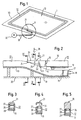
- FIG. 1 is a schematic roof opening 10 with a roof opening 11 shown in perspective.
- the roof opening 11 is of a encircling anti-trap 1 surrounded by a hollow profile 12.
- To close the roof opening 11 is a sliding roof 13 Im Einklemmfall the hollow section 12 is deformed. This will be a Switching triggered, via terminals 18 to the drive unit 30 is forwarded to the sunroof 13.
- the ends 14, 15 of the hollow profile 12 overlap each other.
- FIGS. 3 to 5 show cross sections through the The overlapping area.
- a projection 21 is provided which has a smaller cross-sectional thickness as the hollow profile 12 has.
- the neck 21 tapers starting from the end 14 of the hollow section 12. In this way a smooth transition between the lower end 15 and the upper End 14 of the hollow section 12 is reached.
- the top 33 of the neck 21st in this case runs flush with the top 32 of the hollow section 12, so that a substantially continuous top is formed. hereby a pleasing overall visual impression is achieved.
- the projection 21 is connected to the end 14 of the hollow section 12 via a predetermined bending point 22 reduced flexural rigidity connected. Upon occurrence a force in the direction of arrow 26, the approach 21 thus opposite the end 14 are pivoted.
- the approach 21 is here with a Thickening 24 at its end remote from the hollow profile 12 end on.
- In the central region 25 of the projection 21 is a gap 31 formed between the neck 21 and the hollow section 12.
- the approach 12 thus touches the hollow section 12 only with the thickening 24th As a result, a small contact surface is achieved, which is already at small, in the direction of arrow 26 forces occurring the anti-trap function triggers.
- the upper end 14 of the hollow profile 12, on which the projection 21 is arranged is, has a thickening 23.
- This thickening 23 is included a contact surface 34 spaced from the other end 1 5 on the Hollow profile on.
- the contact surface 34 is in this case at the top 32 of the Hollow sections 12 adapted so that damage avoided and a rapid dissolution can be achieved.
- the anti-trap device 1 allows due to the Neck 21 with a smaller thickness overlap the ends 14, 15 of the Hollow profile 12. As a result, a circumferential anti-trap 1 is provided.
Landscapes
- Engineering & Computer Science (AREA)
- Mechanical Engineering (AREA)
- Seal Device For Vehicle (AREA)
- Power-Operated Mechanisms For Wings (AREA)
Description
Dabei zeigt:
- Figur 1
- eine schematische perspektivische Ansicht eines Dachausschnitts mit einer Dachöffnung;
- Figur 2
- eine vergrößerte Darstellung der Einzelheit X aus Figur 1 im Schnitt;
- Figur 3
- einen Schnitt längs der Linie III-III in Figur 2;
- Figur 4
- einen Schnitt längs der Linie IV-IV in Figur 2; und
- Figur 5
- einen Schnitt längs der Linie V-V in Figur 2.
Claims (13)
- Einklemmschutz für eine kraftbetätigte Schließeinrichtung (13), insbesondere für ein Schiebedach eines Kraftfahrzeugs, mit einem Hohlprofil (12) aus einem elastomeren Material, das mindestens zwei zueinander beabstandete, elektrisch leitfähige Bereiche (27, 28) aufweist, deren Kontakt einen Schaltvorgang zum Ansteuern des Antriebsaggregats (30) der Schließeinrichtung (13) auslöst, dadurch gekennzeichnet, daß das Hohlprofil (12) an mindestens einem seiner Enden (14; 15) mit einem Ansatz (21) versehen ist, der eine geringere Querschnittsdicke als das Hohlprofil (1 2) aufweist.
- Einklemmschutz nach Anspruch 1, dadurch gekennzeichnet, daß sich der Ansatz (21) ausgehend von dem zugeordneten Ende (14) des Hohlprofils (12) verjüngt.
- Einklemmschutz nach Anspruch 1 oder 2, dadurch gekennzeichnet, daß die Oberseite (33) des Ansatzes (21) bündig mit der Oberseite (32) des Hohlprofils (12) verläuft.
- Einklemmschutz nach einem der Ansprüche 1 bis 3, dadurch gekennzeichnet, daß der Ansatz (21) mit dem zugeordneten Ende (14) des Hohlprofils (12) über eine Sollknickstelle (22) verminderter Biegesteifigkeit verbunden ist.
- Einklemmschutz nach einer der Ansprüche 1 bis 4, dadurch gekennzeichnet, daß der Ansatz (21) an einer Stirnseite des Hohlprofils (12) angeordnet ist.
- Einklemmschutz nach einem der Ansprüche 1 bis 5, dadurch gekennzeichnet, daß der Ansatz (21) an seinem von dem Hohlprofil (12) abgewandten Ende eine Verdickung (24) aufweist.
- Einklemmschutz nach einem der Ansprüche 1 bis 6, dadurch gekennzeichnet, daß der Ansatz (21) im Querschnitt im wesentlichen gebogen ausgebildet ist.
- Einklemmschutz nach einem der Ansprüche 1 bis 7, dadurch gekennzeichnet, daß das mit dem Ansatz (21) versehene Ende (14) des Hohlprofils (12) eine Verdickung (23) aufweist.
- Einklemmschutz nach Anspruch 8, dadurch gekennzeichnet, daß die Verdickung (23) eine an die Oberseite (32) des Hohlprofils (12) angepaßte Anlagefläche (34) aufweist.
- Anordnung eines Einklemmschutzes (1) nach einem der vorhergehenden Ansprüche, dadurch gekennzeichnet, daß sich die Enden (14, 15) des Hohlprofils (12) überlappen und der an dem einen Ende (14) vorgesehene Ansatz (21) auf dem Hohlprofil (12) beabstandet zu dem anderen Ende (15) aufliegt.
- Anordnung nach Anspruch 10, dadurch gekennzeichnet, daß die Verdickung (23) des mit dem Ansatz (21) versehenen Endes (14) des Hohlprofils (12) mit ihrer Anlagefläche (27) auf dem Hohlprofil (12) beabstandet zu dem anderen Ende (15) aufliegt.
- Anordnung nach Anspruch 10 oder 11, dadurch gekennzeichnet, daß der Ansatz (21) mit seiner Verdickung (24) auf dem Hohlprofil (12) aufliegt.
- Anordnung nach einem der Ansprüche 10 bis 12, dadurch gekennzeichnet, daß im Mittelbereich (25) des Ansatzes (21) ein Zwischenraum (31) zwischen dem Ansatz (21) und dem Hohlprofil (12) gebildet wird.
Applications Claiming Priority (3)
| Application Number | Priority Date | Filing Date | Title |
|---|---|---|---|
| DE19913879 | 1999-03-26 | ||
| DE19913879A DE19913879C1 (de) | 1999-03-26 | 1999-03-26 | Einklemmschutz für eine kraftbetätigte Schließeinrichtung |
| PCT/EP2000/002634 WO2000058119A1 (de) | 1999-03-26 | 2000-03-24 | Einklemmschutz für eine kraftbetätigte schliesseinrichtung |
Publications (2)
| Publication Number | Publication Date |
|---|---|
| EP1079983A1 EP1079983A1 (de) | 2001-03-07 |
| EP1079983B1 true EP1079983B1 (de) | 2004-02-11 |
Family
ID=7902600
Family Applications (1)
| Application Number | Title | Priority Date | Filing Date |
|---|---|---|---|
| EP00920573A Expired - Lifetime EP1079983B1 (de) | 1999-03-26 | 2000-03-24 | Einklemmschutz für eine kraftbetätigte schliesseinrichtung |
Country Status (6)
| Country | Link |
|---|---|
| US (1) | US7117635B2 (de) |
| EP (1) | EP1079983B1 (de) |
| JP (1) | JP2002540006A (de) |
| DE (2) | DE19913879C1 (de) |
| ES (1) | ES2215637T3 (de) |
| WO (1) | WO2000058119A1 (de) |
Cited By (2)
| Publication number | Priority date | Publication date | Assignee | Title |
|---|---|---|---|---|
| US8493081B2 (en) | 2009-12-08 | 2013-07-23 | Magna Closures Inc. | Wide activation angle pinch sensor section and sensor hook-on attachment principle |
| US9234979B2 (en) | 2009-12-08 | 2016-01-12 | Magna Closures Inc. | Wide activation angle pinch sensor section |
Families Citing this family (6)
| Publication number | Priority date | Publication date | Assignee | Title |
|---|---|---|---|---|
| US7215529B2 (en) * | 2003-08-19 | 2007-05-08 | Schlegel Corporation | Capacitive sensor having flexible polymeric conductors |
| DE102005016252B3 (de) * | 2005-04-08 | 2007-02-15 | Metzeler Automotive Profile Systems Gmbh | Vorrichtung zum Erkennen eines Hindernisses im Öffnungsbereich eines kraftbetätigten Schließelements, insbesondere einer Fensterscheibe eines Kraftfahrzeuges |
| DE102005060043B3 (de) * | 2005-12-15 | 2008-01-03 | Webasto Ag | Öffnungsfähiges Fahrzeugdach |
| DE102006049679B4 (de) * | 2006-10-18 | 2010-08-12 | Johnson Controls Interiors Gmbh & Co. Kg | Fahrzeugtür mit Dichtebene und einem Dichtelement, dessen Enden sich überlappen |
| DE102008045150A1 (de) | 2007-08-30 | 2009-05-07 | Micro-Epsilon Messtechnik Gmbh & Co. Kg | Kapazitiver Einklemmschutz und Verfahren zum Betreiben eines Einklemmschutzes |
| CN103386945B (zh) * | 2013-07-26 | 2015-09-09 | 北京经纬恒润科技有限公司 | 一种车身闭合系统防夹判断方法及系统 |
Family Cites Families (12)
| Publication number | Priority date | Publication date | Assignee | Title |
|---|---|---|---|---|
| JPS63222923A (ja) * | 1987-03-12 | 1988-09-16 | Honda Motor Co Ltd | サンル−フのガイドレ−ル構造 |
| DE4329535C2 (de) * | 1993-08-09 | 1998-03-26 | Metzeler Automotive Profiles | Einklemmschutz für kraftbetätigte Schließeinrichtungen |
| DE9317291U1 (de) * | 1993-11-11 | 1994-12-15 | Haber, Gyula, 88239 Wangen | Schaltprofil als Einklemmschutz für Türen, Fenster und Schiebedächer von Kraftfahrzeugen |
| DE29503160U1 (de) * | 1995-02-24 | 1995-04-27 | REHAU AG + Co., 95111 Rehau | Kontaktleiste für elektrische Leitungen |
| US5592060A (en) * | 1995-07-10 | 1997-01-07 | Webasto Sunroofs Inc. | System for sensing an obstruction between a movable panel and a stationary panel frame |
| DE19602744C2 (de) * | 1996-01-19 | 1999-04-29 | Mayser Gmbh & Co | Sicherheitsschaltleistenanordnung |
| DE19701412A1 (de) * | 1997-01-17 | 1998-07-23 | Dewitron Elektronik Gmbh | Bandförmige und flexible Schaltungsanordnungen |
| LU90049B1 (de) * | 1997-04-10 | 1998-10-12 | Iee Sarl | Vorrichtung zur Einklemmerkennung |
| DE19720713C1 (de) * | 1997-05-16 | 1998-05-28 | Metzeler Automotive Profiles | Dichtungsprofil zur Abdichtung einer kraftbetätigten Schließeinrichtung |
| DE19750711C2 (de) * | 1997-11-15 | 1999-09-02 | Daimler Benz Ag | Deckel eines öffnungsfähigen Fahrzeugdachs |
| DE19913106C1 (de) * | 1999-03-23 | 2000-05-04 | Metzeler Automotive Profiles | Einklemmschutz für eine kraftbetätigte Schließeinrichtung |
| US6389752B1 (en) * | 1999-06-21 | 2002-05-21 | Schlegel Corporation | Touch sensitive trapping protector for power operated closing devices |
-
1999
- 1999-03-26 DE DE19913879A patent/DE19913879C1/de not_active Expired - Fee Related
-
2000
- 2000-03-24 WO PCT/EP2000/002634 patent/WO2000058119A1/de not_active Ceased
- 2000-03-24 ES ES00920573T patent/ES2215637T3/es not_active Expired - Lifetime
- 2000-03-24 JP JP2000607840A patent/JP2002540006A/ja active Pending
- 2000-03-24 EP EP00920573A patent/EP1079983B1/de not_active Expired - Lifetime
- 2000-03-24 DE DE50005243T patent/DE50005243D1/de not_active Expired - Lifetime
-
2002
- 2002-08-09 US US10/216,499 patent/US7117635B2/en not_active Expired - Lifetime
Cited By (3)
| Publication number | Priority date | Publication date | Assignee | Title |
|---|---|---|---|---|
| US8493081B2 (en) | 2009-12-08 | 2013-07-23 | Magna Closures Inc. | Wide activation angle pinch sensor section and sensor hook-on attachment principle |
| US9234979B2 (en) | 2009-12-08 | 2016-01-12 | Magna Closures Inc. | Wide activation angle pinch sensor section |
| US9417099B2 (en) | 2009-12-08 | 2016-08-16 | Magna Closures Inc. | Wide activation angle pinch sensor section |
Also Published As
| Publication number | Publication date |
|---|---|
| EP1079983A1 (de) | 2001-03-07 |
| US20030042766A1 (en) | 2003-03-06 |
| ES2215637T3 (es) | 2004-10-16 |
| WO2000058119A1 (de) | 2000-10-05 |
| US7117635B2 (en) | 2006-10-10 |
| DE19913879C1 (de) | 2000-06-08 |
| JP2002540006A (ja) | 2002-11-26 |
| DE50005243D1 (de) | 2004-03-18 |
Similar Documents
| Publication | Publication Date | Title |
|---|---|---|
| DE19720713C1 (de) | Dichtungsprofil zur Abdichtung einer kraftbetätigten Schließeinrichtung | |
| EP1163415A1 (de) | Dichtungsprofil zum abdichten einer kraftbetätigten schliesseinrichtung | |
| DE69601501T2 (de) | Sicherheitseinrichtung für bewegliches fenster | |
| DE2745120B1 (de) | Tuerfuehrung,insbesondere fuer die Hecktuere eines Kombinationskraftwagens | |
| DE69632372T2 (de) | Kontaktschlauch | |
| DE19913879C1 (de) | Einklemmschutz für eine kraftbetätigte Schließeinrichtung | |
| EP1876048B2 (de) | Fingerschutzleiste, insbesondere für Aussen- und Innenschwenktüren | |
| DE69619932T2 (de) | Kabelschalter | |
| EP2329976B1 (de) | Schiebetüre für ein Fahrzeug | |
| EP1161611B1 (de) | Spaltabdeckanordnung | |
| DE4324645C2 (de) | Elastisches Dichtungsprofil für Fenster, Türen o. dgl. | |
| DE19913106C1 (de) | Einklemmschutz für eine kraftbetätigte Schließeinrichtung | |
| EP0385197B1 (de) | Fahrzeugtüre | |
| DE19632592C2 (de) | Schaltleiste mit einem bei einer Krafteinleitung auf seine Außenseite elastisch nachgiebigen Hohlprofil | |
| EP1279542B1 (de) | Dichtungsprofil fÜr einen Kraftwagen | |
| EP1348585B1 (de) | Verfahrbarer Deckel für Fahrzeugdach sowie Schiebehebedach-Modul | |
| DE10348444B4 (de) | Verschwenkbares Deckelteil in einem Fahrzeug | |
| DE10066168B4 (de) | Dichtungsanordnung für ein Kraftfahrzeug und Verfahren zur Montage eines Führungs- und Dichtungsprofils an einem Rahmen | |
| EP1491377A2 (de) | Fahrzeugdach mit Geräuschreduzierung | |
| DE8711470U1 (de) | Mitnehmerplatte für einen Fensterheber | |
| DE2858326C2 (de) | ||
| EP1715128B1 (de) | Schaltprofil | |
| DE29710499U1 (de) | Sicherheitsvorrichtung für verschiebbare Fensterscheiben | |
| DE3438603A1 (de) | Schaltschrank | |
| DE60203772T2 (de) | Fensterheber |
Legal Events
| Date | Code | Title | Description |
|---|---|---|---|
| PUAI | Public reference made under article 153(3) epc to a published international application that has entered the european phase |
Free format text: ORIGINAL CODE: 0009012 |
|
| 17P | Request for examination filed |
Effective date: 20001027 |
|
| AK | Designated contracting states |
Kind code of ref document: A1 Designated state(s): AT BE CH CY DE DK ES FI FR GB GR IE IT LI LU MC NL PT SE |
|
| GRAP | Despatch of communication of intention to grant a patent |
Free format text: ORIGINAL CODE: EPIDOSNIGR1 |
|
| RAP1 | Party data changed (applicant data changed or rights of an application transferred) |
Owner name: WEBASTO VEHICLE SYSTEMS INTERNATIONAL GMBH Owner name: METZELER AUTOMOTIVE PROFILE SYSTEMS GMBH |
|
| GRAS | Grant fee paid |
Free format text: ORIGINAL CODE: EPIDOSNIGR3 |
|
| GRAA | (expected) grant |
Free format text: ORIGINAL CODE: 0009210 |
|
| AK | Designated contracting states |
Kind code of ref document: B1 Designated state(s): DE ES FR GB IT NL |
|
| REG | Reference to a national code |
Ref country code: GB Ref legal event code: FG4D Free format text: NOT ENGLISH |
|
| REG | Reference to a national code |
Ref country code: IE Ref legal event code: FG4D Free format text: GERMAN |
|
| REF | Corresponds to: |
Ref document number: 50005243 Country of ref document: DE Date of ref document: 20040318 Kind code of ref document: P |
|
| GBT | Gb: translation of ep patent filed (gb section 77(6)(a)/1977) |
Effective date: 20040524 |
|
| REG | Reference to a national code |
Ref country code: IE Ref legal event code: FD4D |
|
| REG | Reference to a national code |
Ref country code: ES Ref legal event code: FG2A Ref document number: 2215637 Country of ref document: ES Kind code of ref document: T3 |
|
| ET | Fr: translation filed | ||
| PLBE | No opposition filed within time limit |
Free format text: ORIGINAL CODE: 0009261 |
|
| STAA | Information on the status of an ep patent application or granted ep patent |
Free format text: STATUS: NO OPPOSITION FILED WITHIN TIME LIMIT |
|
| 26N | No opposition filed |
Effective date: 20041112 |
|
| PGFP | Annual fee paid to national office [announced via postgrant information from national office to epo] |
Ref country code: NL Payment date: 20120327 Year of fee payment: 13 |
|
| REG | Reference to a national code |
Ref country code: NL Ref legal event code: V1 Effective date: 20131001 |
|
| REG | Reference to a national code |
Ref country code: DE Ref legal event code: R082 Ref document number: 50005243 Country of ref document: DE Representative=s name: FLUEGEL PREISSNER KASTEL SCHOBER, DE |
|
| REG | Reference to a national code |
Ref country code: DE Ref legal event code: R082 Ref document number: 50005243 Country of ref document: DE Representative=s name: FLUEGEL PREISSNER KASTEL SCHOBER, DE Effective date: 20131118 Ref country code: DE Ref legal event code: R081 Ref document number: 50005243 Country of ref document: DE Owner name: WEBASTO AG, DE Free format text: FORMER OWNER: WEBASTO AG, METZELER AUTOMOTIVE PROFILE SYS, , DE Effective date: 20131118 Ref country code: DE Ref legal event code: R081 Ref document number: 50005243 Country of ref document: DE Owner name: COOPER STANDARD GMBH, DE Free format text: FORMER OWNER: WEBASTO AG, METZELER AUTOMOTIVE PROFILE SYS, , DE Effective date: 20131118 Ref country code: DE Ref legal event code: R082 Ref document number: 50005243 Country of ref document: DE Representative=s name: FLUEGEL PREISSNER KASTEL SCHOBER PATENTANWAELT, DE Effective date: 20131118 Ref country code: DE Ref legal event code: R081 Ref document number: 50005243 Country of ref document: DE Owner name: COOPER STANDARD GMBH, DE Free format text: FORMER OWNERS: WEBASTO AG, 82131 GAUTING, DE; METZELER AUTOMOTIVE PROFILE SYSTEMS GMBH, 88131 LINDAU, DE Effective date: 20131118 Ref country code: DE Ref legal event code: R081 Ref document number: 50005243 Country of ref document: DE Owner name: WEBASTO AG, DE Free format text: FORMER OWNERS: WEBASTO AG, 82131 GAUTING, DE; METZELER AUTOMOTIVE PROFILE SYSTEMS GMBH, 88131 LINDAU, DE Effective date: 20131118 Ref country code: DE Ref legal event code: R082 Ref document number: 50005243 Country of ref document: DE Representative=s name: FLUEGEL PREISSNER SCHOBER SEIDEL PATENTANWAELT, DE Effective date: 20131118 |
|
| PG25 | Lapsed in a contracting state [announced via postgrant information from national office to epo] |
Ref country code: NL Free format text: LAPSE BECAUSE OF NON-PAYMENT OF DUE FEES Effective date: 20131001 |
|
| REG | Reference to a national code |
Ref country code: ES Ref legal event code: PC2A Owner name: COOPER STANDARD GMBH Effective date: 20141003 |
|
| REG | Reference to a national code |
Ref country code: DE Ref legal event code: R079 Ref document number: 50005243 Country of ref document: DE Free format text: PREVIOUS MAIN CLASS: B60J0010120000 Ipc: B60J0010820000 |
|
| REG | Reference to a national code |
Ref country code: FR Ref legal event code: PLFP Year of fee payment: 17 |
|
| REG | Reference to a national code |
Ref country code: FR Ref legal event code: PLFP Year of fee payment: 18 |
|
| PGFP | Annual fee paid to national office [announced via postgrant information from national office to epo] |
Ref country code: FR Payment date: 20170323 Year of fee payment: 18 |
|
| PGFP | Annual fee paid to national office [announced via postgrant information from national office to epo] |
Ref country code: GB Payment date: 20170327 Year of fee payment: 18 |
|
| PGFP | Annual fee paid to national office [announced via postgrant information from national office to epo] |
Ref country code: IT Payment date: 20170323 Year of fee payment: 18 Ref country code: ES Payment date: 20170323 Year of fee payment: 18 |
|
| REG | Reference to a national code |
Ref country code: FR Ref legal event code: CD Owner name: COOPER STANDARD GMBH, DE Effective date: 20170831 |
|
| PGFP | Annual fee paid to national office [announced via postgrant information from national office to epo] |
Ref country code: DE Payment date: 20180320 Year of fee payment: 19 |
|
| GBPC | Gb: european patent ceased through non-payment of renewal fee |
Effective date: 20180324 |
|
| PG25 | Lapsed in a contracting state [announced via postgrant information from national office to epo] |
Ref country code: GB Free format text: LAPSE BECAUSE OF NON-PAYMENT OF DUE FEES Effective date: 20180324 Ref country code: IT Free format text: LAPSE BECAUSE OF NON-PAYMENT OF DUE FEES Effective date: 20180324 |
|
| PG25 | Lapsed in a contracting state [announced via postgrant information from national office to epo] |
Ref country code: FR Free format text: LAPSE BECAUSE OF NON-PAYMENT OF DUE FEES Effective date: 20180331 |
|
| REG | Reference to a national code |
Ref country code: ES Ref legal event code: FD2A Effective date: 20190911 |
|
| REG | Reference to a national code |
Ref country code: DE Ref legal event code: R119 Ref document number: 50005243 Country of ref document: DE |
|
| PG25 | Lapsed in a contracting state [announced via postgrant information from national office to epo] |
Ref country code: ES Free format text: LAPSE BECAUSE OF NON-PAYMENT OF DUE FEES Effective date: 20180325 |
|
| PG25 | Lapsed in a contracting state [announced via postgrant information from national office to epo] |
Ref country code: DE Free format text: LAPSE BECAUSE OF NON-PAYMENT OF DUE FEES Effective date: 20191001 |