EP1079161B1 - Anordnung zur Verhinderung unerwünschter Drücke beim Absperren oder Drosseln der Flüssigkeitsförderung in einer Rohrleitung - Google Patents
Anordnung zur Verhinderung unerwünschter Drücke beim Absperren oder Drosseln der Flüssigkeitsförderung in einer Rohrleitung Download PDFInfo
- Publication number
- EP1079161B1 EP1079161B1 EP00115442A EP00115442A EP1079161B1 EP 1079161 B1 EP1079161 B1 EP 1079161B1 EP 00115442 A EP00115442 A EP 00115442A EP 00115442 A EP00115442 A EP 00115442A EP 1079161 B1 EP1079161 B1 EP 1079161B1
- Authority
- EP
- European Patent Office
- Prior art keywords
- brake
- pipeline
- shut
- pressure
- isolation valve
- Prior art date
- Legal status (The legal status is an assumption and is not a legal conclusion. Google has not performed a legal analysis and makes no representation as to the accuracy of the status listed.)
- Expired - Lifetime
Links
Images

Classifications
-
- F—MECHANICAL ENGINEERING; LIGHTING; HEATING; WEAPONS; BLASTING
- F16—ENGINEERING ELEMENTS AND UNITS; GENERAL MEASURES FOR PRODUCING AND MAINTAINING EFFECTIVE FUNCTIONING OF MACHINES OR INSTALLATIONS; THERMAL INSULATION IN GENERAL
- F16K—VALVES; TAPS; COCKS; ACTUATING-FLOATS; DEVICES FOR VENTING OR AERATING
- F16K47/00—Means in valves for absorbing fluid energy
- F16K47/02—Means in valves for absorbing fluid energy for preventing water-hammer or noise
- F16K47/023—Means in valves for absorbing fluid energy for preventing water-hammer or noise for preventing water-hammer, e.g. damping of the valve movement
-
- Y—GENERAL TAGGING OF NEW TECHNOLOGICAL DEVELOPMENTS; GENERAL TAGGING OF CROSS-SECTIONAL TECHNOLOGIES SPANNING OVER SEVERAL SECTIONS OF THE IPC; TECHNICAL SUBJECTS COVERED BY FORMER USPC CROSS-REFERENCE ART COLLECTIONS [XRACs] AND DIGESTS
- Y02—TECHNOLOGIES OR APPLICATIONS FOR MITIGATION OR ADAPTATION AGAINST CLIMATE CHANGE
- Y02E—REDUCTION OF GREENHOUSE GAS [GHG] EMISSIONS, RELATED TO ENERGY GENERATION, TRANSMISSION OR DISTRIBUTION
- Y02E20/00—Combustion technologies with mitigation potential
- Y02E20/14—Combined heat and power generation [CHP]
-
- Y—GENERAL TAGGING OF NEW TECHNOLOGICAL DEVELOPMENTS; GENERAL TAGGING OF CROSS-SECTIONAL TECHNOLOGIES SPANNING OVER SEVERAL SECTIONS OF THE IPC; TECHNICAL SUBJECTS COVERED BY FORMER USPC CROSS-REFERENCE ART COLLECTIONS [XRACs] AND DIGESTS
- Y10—TECHNICAL SUBJECTS COVERED BY FORMER USPC
- Y10T—TECHNICAL SUBJECTS COVERED BY FORMER US CLASSIFICATION
- Y10T137/00—Fluid handling
- Y10T137/8593—Systems
Definitions
- the invention relates to an arrangement for preventing undesirable pressures which fast valve operations, especially with fast shut-off or Throttling processes in liquid-conveying pipelines by actuating Fast-acting valves or flaps (shut-off valve) occur when shortly after the liquid column in motion is braked when the valve is actuated becomes. Upstream of the valve rises due to the deceleration of the fluid the pressure quickly. There is a pressure surge, which is a burden on the Pipe, their storage and for the valve itself. Sinks downstream the pressure. If it falls below the vapor pressure of the liquid, it happens to form a cavitation bubble, which then collapses again, what in turn leads to pressure surges, so-called cavitation blows. In some cases, e.g. at Using certain piping materials is a lower limit for that permissible pressure specified, which fell below during the shut-off or throttling process can be.
- Pressure surges are usually caused by the fixed setting of a reduced closing or Throttle valve speed reduced.
- Experience has shown that the Pressure surge on the inlet side can only be mastered if the system and Operating conditions of the pipeline, the setting parameters of the valve correspond.
- it is difficult to blow a cavitation downstream Shut-off valve by reducing the closing or throttling speed prevent because a cavitation bubble behind the valve even with larger closing or throttling times, especially if the pipeline is very long (Thorley, A.R.D., "Fluid Transients in Pipeline Systems", D&L George LTD, 1991, Hadley Wood, Bamet, GB).
- a way to prevent pressure surges upstream of the closing or Throttle valve is the quick discharge of the transport medium into another Line section that reaches a limit of pressure or mass flow is opened (DD-PS 211615).
- a similar process is used by Gustavsson for the Avoiding pressure surges in district heating pipes with flow and return traced. Here, the flow and return are coupled when closing, so that an increase in pressure is prevented (WO-PS 94/02775).
- Redirecting the transport medium with subsequent slow closing of the main valve is also known (DD-OS 23 46 754).
- a disadvantage of the latter inventions is that in addition to a high metrological effort additional line sections and / or buffer tank in the transport line system must be integrated.
- Another possibility is to measure and limit the line pressure or the rate of pressure increase by a fast pressure measuring and control system.
- the fast controller interrupts when a maximum pressure is exceeded or a maximum rate of pressure increase the closing or Throttling process of the valve (DD-PS 201 041).
- This procedure places the highest Demands on measurement and control technology.
- the drive of the Closing or throttle valve in very tight time limits of a few milliseconds in be able to interrupt the closing or throttling process.
- One way of preventing the cavitation blow is by Ventilation or the feeding of other, non-condensable gases into the Pipe behind the shut-off valve (Raschke, E., Salla, M., Hültenschmidt, W .: "Pressure surge damped, pipeline protected - condensation shocks in pipelines under the dampening influence of gases ", Anlagenstechnik 7-8 / 97, S. 45-49).
- a ventilation valve is located just behind the shut-off valve attached, if a vacuum occurs behind the shut-off valve opens automatically and allows a certain amount of air to enter the transport line. It is assumed that the negative pressure due to the presence of a Cavitation bubble occurs.
- a shut-off device on pressurized water pipes is also known, in which the Closing member is connected to a fluid brake, which is from a Pressure relay is controlled, which the closing movement of the closing element in Dependence on the flow in the pressure line inhibits (CH 186 625).
- the object of the invention is to propose an arrangement with which a closing or Throttling process of the shut-off valve regardless of changing system and Operating conditions of the pipeline takes place in the shortest possible time without this a predetermined pressure in the pipeline is exceeded or that downstream a pressure drop below a specified limit value from the shut-off valve is prevented.
- the arrangement is said to be without feeding air or other Gases in the pipeline get along to the contamination of the fluid excluded. Elaborate equipment, such as an air boiler, complicated control equipment for the closing or throttle valve and extensive installations for the deflection of the transport liquid should be avoided.
- the prevention of an undesirable increase in pressure is done by the Reduce the closing or throttling speed of the shut-off valve with the help a hydraulic brake on the drive linkage such as axis of rotation, spindle or lifting rod of the shut-off valve, and the pressure of the transport liquid is operated immediately upstream of the shut-off valve.
- a hydraulic brake on the drive linkage such as axis of rotation, spindle or lifting rod of the shut-off valve
- A is used to limit the pressure drop downstream of the shut-off valve Brake used with the fluid immediately downstream of the Shut-off valve is connected.
- the brake which is also on the drive linkage, So the axis of rotation, the spindle or the lifting rod of the shut-off valve acts in this way switched that a decrease in pressure to apply the brake and thus to Slowing the closing or throttling process leads. If the pressure rises again, the brake releases and the closing or throttling process continues.
- the liquid to be pumped into the hydraulic brake or the brake booster arrives. This is particularly so the case when corrosion, abrasion or blockage can occur. It the brake can be operated with a separate brake fluid and the Pressure transfer from the fluid to the brake fluid through a elastic membrane that separates both liquids.
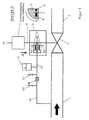
- Figure 1 in its design with the pipeline upstream 1 and downstream of the shut-off valve 3, in which the liquid flows in the direction of flow (arrow) flows with the drive linkage 4 as the drive shaft, the drive 5, the hydraulic brake 6 as a disc brake, the brake cylinders 7, the Brake shoes 8, the brake disc 9, the connecting lines 10 and 11, the Membrane 16, the brake fluid container 13, the closing or throttle signal 14, as well as the ventilation fittings E1, E2, E3 and E4 is the transport liquid that flows in the pipeline 1 or 2 through the shut-off valve, via a connecting line 10, the upstream near the shut-off valve 3 with the pipeline 1 is connected to an elastic membrane 16 in connection.
- the pressure of Delivery fluid is supplied to the brake fluid in the membrane 16 Transfer line 11 and is present in the brake cylinders 7.
- the drive 5 performs a rotary movement the drive shaft 4, which leads to the closing or throttling of the shut-off valve 3.
- the pressure in line 1 increases due to the braking of the delivery liquid.
- the Pressure increase is transmitted via the connecting lines 10 and 11 and the Diaphragm 16 on the brake cylinder 7, whereby the brake shoes 8 to the Brake disc 9 are pressed.
- the rotational movement of the drive shaft 4 is thereby delayed until the pressure in the pipeline 1 drops again. This will ensures that the pressure in the pipeline 1 does not reach a maximum pressure can exceed.
- a prerequisite for the correct functioning of the arrangement is that the lines 10, 11 and the brake cylinders 7 via the bleed valves E1 - E4 perfectly be vented. If the type of liquid to be pumped allows it to flow into the Brake cylinder may arrive without undesirable corrosion, abrasion or The membrane 16 can be dispensed with to cause clogging effects.
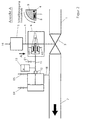
- the pressure in line 2 drops due to the braking of the delivery liquid.
- the Pressure drop is transmitted via the connecting lines 15 and 11 and the Brake booster 12 on the brake cylinder 7, whereby the brake shoes 8 to the Brake disc 9 are pressed.
- the rotational movement of the drive shaft 4 is thereby delayed until the pressure in the pipe 2 rises again. This will ensures that the pressure in the pipeline 2 does not reach a minimum pressure can fall below.
- the brake booster 12 is in this embodiment with elastic membranes according to claim 5 fitted.
- the shut-off valve 3 in which the liquid in the direction of flow (arrow) flows with the drive shaft 4, the drive 5, the disc brake 6, the Brake cylinders 7, the brake shoes 8, the brake disc 9, the connecting lines 10 and 11, the brake booster 12, the brake fluid reservoir 13, the closing or throttle signal 14, the connecting line 15 and the Vent fittings E1, E2, E3, E4 and E5 is the transport liquid that is in the Pipe 1 or 2 flows through the shut-off valve, via a connecting line 15, which is connected downstream of the shut-off valve 3 to the pipeline 2, and via a connecting line 10, which is upstream near the shut-off valve 3 is connected to the pipeline 1, with the brake booster 12 in Connection.
- the connecting line 10 is at the plus input and the Connection line 15 to the negative input of the brake booster 12 connected.
- the pressure difference of the pumped liquid above the shut-off valve 3 is amplified by the brake booster 12 to the brake fluid in the Transfer line 11 and is present in the brake cylinders 7. at open shut-off valve, the pressure difference is small, so that an undesirable Response of the disc brake 6 solely by the normal pressure in the pipe 1 and 2 is prevented.
- the throttle signal 14 is activated, the drive 5 a rotational movement of the drive shaft 4, which for partial closing or Throttling the shut-off valve 3 leads.
- the brake booster 12 is in this embodiment with elastic membranes according to claim 5 equipped.
Landscapes
- Engineering & Computer Science (AREA)
- General Engineering & Computer Science (AREA)
- Mechanical Engineering (AREA)
- Valves And Accessory Devices For Braking Systems (AREA)
- Pipeline Systems (AREA)
- Details Of Valves (AREA)
- Lift Valve (AREA)
- Control And Other Processes For Unpacking Of Materials (AREA)
- Sampling And Sample Adjustment (AREA)
Description
Claims (7)
- Anordnung zur Verhinderung eines unerwünscht hohen Drucks beim Absperren oder Drosseln der Flüssigkeitsförderung stromaufwärts einer Absperrarmatur (3) in Form einer Absperrklappe, mit der die Flüssigkeitsförderung in einer Rohrleitung (1,2) abgesperrt oder gedrosselt wird, enthaltend eine Antriebswelle (4) und einen Antrieb (5), dadurch gekennzeichnet, daß an dem Antriebswelle (4) der Absperrarmatur (3) eine hydraulisch betätigte Scheiben bremse (6) angebracht ist und daß der Bremszylinder (7) der Bremse (6) über eine Verbindungsleitung (10) stromaufwärts nahe der Absperrarmatur (3) an die Rohrleitung (1) angeschlossen ist.
- Anordnung zur Verhinderung eines unerwünscht niedrigen Drucks beim Absperren oder Drosseln der Flüssigkeitsförderung stromaufwärts einer Absperrarmatur (3) in Form einer Absperrklappe, mit der die Flüssigkeitsförderung in einer Rohrleitung (1,2) abgesperrt oder gedrosselt wird, enthaltend eine Antriebswelle (4) und einen Antrieb (5), dadurch gekennzeichnet, daß an dem Antriebswelle (4) der Absperrarmatur (3) eine hydraulisch betätigte Scheiben bremse (6) angebracht ist und daß der Bremszylinder (7) der Bremse (6) über eine Verbindungsleitung (15) stromabwärts nahe der Absperrarmatur (3) an die Rohrleitung (2) angeschlossen ist.
- Anordnung zur Verhinderung eines unerwünscht hohen Drucks oder eines unerwünscht niedrigen Drucks stromaufwärts bzw. stromabwärts einer Absperrarmatur (3) in Form einer Absperrklappe beim Absperren oder Drosseln der Flüssigkeitsförderung in einer Rohrleitung (1,2), enthaltend ein Antriebswelle (4) and einen Antrieb (5),
dadurch gekennzeichnet, daß an dem Antriebswelle (4) der Absperrarmatur (3) eine hydraulisch betätigte Scheibenbremse (6) angebracht ist,
daß der Bremszylinder (7) der Bremse über eine Verbindungsleitung (10) stromaufwärts nahe der Absperrarmatur (8) an die Rohrleitung (1) und über eine andere Verbindungsleitung (15) stromabwärts nahe der Absperrarmatur (8) an die Rohrleitung (2) stromabwärts angeschlossen ist, wobei die hydraulisch betätigte Scheibenbremse (6) doppelt wirkend ausgeführt ist, deren Bremswirkung durch die Druckdifferenz zwischen einem Plus- und einem Minuseingang bestimmt wird und
daß der Pluseingang des Bremszylinders (7) über die Verbindungsleitung (10) mit der Rohrleitung (1) stromaufwärts nahe der Absperrarmatur (3) und der Minuseingang über die Verbindungsleitung (15) mit der Rohrleitung (2) stromabwärts nahe der Absperrarmatur (3) verbunden ist. - Anordnung nach Anspruch 1, dadurch gekennzeichnet, daß ein Bremskraftverstärker (12) zwischen den Bremszylinder (7) und die Rohrleitung (1) eingebaut ist.
- Anordnung nach Anspruch 2, dadurch gekennzeichnet, daß ein Bremskraftverstärker (12) zwischen Bremszylinder (7) und Rohrleitung (2) eingebaut ist.
- Anordnung nach Anspruch 3, dadurch gekennzeichnet, daß ein Bremskraftverstärker (12) zwischen Bremszylinder (7) und Rohrleitungen (1) und (2) eingebaut ist.
- Anordnung nach den Ansprüchen 1 bis 6, dadurch gekennzeichnet, daß eine elastische Membran (16) in die Verbindungsleitung (10) oder (15) eingebaut ist und die Verbindungsleitungen zwischen Membran (16) und Bremszylinder (7) mit einer von der Förderflüssigkeit verschiedenen Bremsflüssigkeit gefüllt sind.
Priority Applications (1)
| Application Number | Priority Date | Filing Date | Title |
|---|---|---|---|
| DK00115442T DK1079161T3 (da) | 1999-08-24 | 2000-07-18 | Indretning til at forhindre uönskede tryk ved afspærring eller neddrosling af væsketransporten i en rörledning |
Applications Claiming Priority (2)
| Application Number | Priority Date | Filing Date | Title |
|---|---|---|---|
| DE19940096A DE19940096C2 (de) | 1999-08-24 | 1999-08-24 | Anordnung zur Verhinderung unerwünschter Drücke beim Absperren oder Drosseln der Flüssigkeitsförderung in einer Rohrleitung |
| DE19940096 | 1999-08-24 |
Publications (3)
| Publication Number | Publication Date |
|---|---|
| EP1079161A2 EP1079161A2 (de) | 2001-02-28 |
| EP1079161A3 EP1079161A3 (de) | 2002-08-28 |
| EP1079161B1 true EP1079161B1 (de) | 2004-12-15 |
Family
ID=7919420
Family Applications (1)
| Application Number | Title | Priority Date | Filing Date |
|---|---|---|---|
| EP00115442A Expired - Lifetime EP1079161B1 (de) | 1999-08-24 | 2000-07-18 | Anordnung zur Verhinderung unerwünschter Drücke beim Absperren oder Drosseln der Flüssigkeitsförderung in einer Rohrleitung |
Country Status (7)
| Country | Link |
|---|---|
| US (1) | US6347783B1 (de) |
| EP (1) | EP1079161B1 (de) |
| AT (1) | ATE285046T1 (de) |
| DE (2) | DE19940096C2 (de) |
| DK (1) | DK1079161T3 (de) |
| ES (1) | ES2234483T3 (de) |
| PT (1) | PT1079161E (de) |
Cited By (1)
| Publication number | Priority date | Publication date | Assignee | Title |
|---|---|---|---|---|
| CN102301170A (zh) * | 2009-01-29 | 2011-12-28 | 西门子公司 | 速闭阀 |
Families Citing this family (3)
| Publication number | Priority date | Publication date | Assignee | Title |
|---|---|---|---|---|
| DE102004025983B4 (de) * | 2004-05-27 | 2007-09-06 | Fraunhofer-Gesellschaft zur Förderung der angewandten Forschung e.V. | Vorrichtung zur Vermeidung von Druckstößen in Rohrleitungssystemen |
| US7021255B2 (en) * | 2004-06-21 | 2006-04-04 | Ford Global Technologies, Llc | Initialization of electromechanical valve actuator in an internal combustion engine |
| US7404543B2 (en) * | 2006-09-12 | 2008-07-29 | Victaulic Company | Slow closing actuator and valve |
Family Cites Families (10)
| Publication number | Priority date | Publication date | Assignee | Title |
|---|---|---|---|---|
| DE201041C (de) | ||||
| DE211615C (de) | ||||
| CH186625A (de) * | 1936-03-13 | 1936-09-30 | Von Roll Ag | Absperrvorrichtung an Druckwasserleitungen. |
| CH562988A5 (de) * | 1973-08-13 | 1975-06-13 | Bbc Brown Boveri & Cie | |
| DD201041A1 (de) * | 1981-07-22 | 1983-06-29 | Froehlich Klaus Peter | Verfahren und einrichtung zur druckstossbegrenzung in rohrleitungen |
| DD211615A1 (de) * | 1982-11-17 | 1984-07-18 | Inst Energieversorgung | Schaltungsanordnung zur druckstossbegrenzung bei absperrvorgaengen in rohrleitungsnetzen |
| DE4004700A1 (de) * | 1990-02-15 | 1991-08-22 | Ideal Standard | Schliessdaempfer fuer eine sanitaere wasserarmatur |
| DE4013176A1 (de) * | 1990-04-25 | 1991-10-31 | Siemens Ag | Armatur zum absperren einer stroemung |
| SE500272C2 (sv) * | 1992-07-20 | 1994-05-24 | Fludex Ab | Anordning för snabbsektionering |
| DE19815242A1 (de) * | 1998-04-04 | 1999-10-07 | Rossendorf Forschzent | Anordnung zur Verhinderung eines Kavitationsschlages beim schnellen Absperren einer zum Transport von Flüssigkeiten genutzten Rohrleitung |
-
1999
- 1999-08-24 DE DE19940096A patent/DE19940096C2/de not_active Expired - Fee Related
-
2000
- 2000-06-26 US US09/602,881 patent/US6347783B1/en not_active Expired - Fee Related
- 2000-07-18 DK DK00115442T patent/DK1079161T3/da active
- 2000-07-18 EP EP00115442A patent/EP1079161B1/de not_active Expired - Lifetime
- 2000-07-18 DE DE50008943T patent/DE50008943D1/de not_active Expired - Lifetime
- 2000-07-18 AT AT00115442T patent/ATE285046T1/de not_active IP Right Cessation
- 2000-07-18 ES ES00115442T patent/ES2234483T3/es not_active Expired - Lifetime
- 2000-07-18 PT PT00115442T patent/PT1079161E/pt unknown
Cited By (2)
| Publication number | Priority date | Publication date | Assignee | Title |
|---|---|---|---|---|
| CN102301170A (zh) * | 2009-01-29 | 2011-12-28 | 西门子公司 | 速闭阀 |
| CN102301170B (zh) * | 2009-01-29 | 2013-08-21 | 西门子公司 | 速闭阀 |
Also Published As
| Publication number | Publication date |
|---|---|
| EP1079161A3 (de) | 2002-08-28 |
| DE19940096C2 (de) | 2001-08-16 |
| US6347783B1 (en) | 2002-02-19 |
| DE19940096A1 (de) | 2001-03-08 |
| DE50008943D1 (de) | 2005-01-20 |
| EP1079161A2 (de) | 2001-02-28 |
| PT1079161E (pt) | 2006-05-31 |
| ATE285046T1 (de) | 2005-01-15 |
| ES2234483T3 (es) | 2005-07-01 |
| DK1079161T3 (da) | 2005-04-25 |
Similar Documents
| Publication | Publication Date | Title |
|---|---|---|
| JP5718381B2 (ja) | 自閉式停止弁に用いられる流れ制御アクチュエータ装置 | |
| CN101558261B (zh) | 用于压力传导系统的过压保护的安全装置 | |
| DE19940096C2 (de) | Anordnung zur Verhinderung unerwünschter Drücke beim Absperren oder Drosseln der Flüssigkeitsförderung in einer Rohrleitung | |
| DE10026843A1 (de) | Steueranordnung für ein durch Unterdruck betätigbares Absperrventil sowie ein Verfahren zum Steuern eines solchen | |
| EP1286090A2 (de) | Schnellschlussventil | |
| EP0327599A1 (de) | Rohrbruchsicherheitsventil | |
| DE1251234B (de) | Bodenbefullungsemnchtung zum Befullen und Entleeren eines mehrere Abteile aufweisenden Tanks | |
| DE102004025983B4 (de) | Vorrichtung zur Vermeidung von Druckstößen in Rohrleitungssystemen | |
| DE2013681A1 (en) | Rapid sealing of pressurized conduits innucl | |
| DE3829726A1 (de) | Vorgesteuertes druckstoss-nebenauslassventil | |
| CH446185A (de) | Einrichtung zur kontinuierlichen hydropneumatischen Förderung staubartiger Stoffe | |
| DE102015200937A1 (de) | Fluidventil, insbesondere für Fahrzeuge | |
| EP0947755A2 (de) | Anordnung zur Verhinderung eines Kavitationsschlages beim schnellen Absperren einer zum Transport von Flüssigkeiten genutzten Rohrleitung | |
| DE4326884A1 (de) | Volumenstromregler für pneumatische Feststofförderung | |
| AT378609B (de) | Zuschaltventil zum zuschalten eines hochdruckmediums in ein mit niederdruck beaufschlagtes system | |
| DD221151A1 (de) | Druckabhaengig gesteuertes einlassventil fuer pneumatische foerderleitungen | |
| DE459877C (de) | Sicherheitsvorrichtung fuer auf eine gemeinsame Dampfleitung arbeitende Kessel mit verschiedenem Betriebsdruck, bei welchen die Reduktion des hoeher gespannten Dampfs durch einen hydraulischen Druckregler erfolgt | |
| DE101467C (de) | ||
| DE644816C (de) | Druckminder- und -regleranlage fuer Hochdruckgasleitungen | |
| DE1034440B (de) | Duesenregelschieber | |
| DE680739C (de) | Hochhubsicherheitsventil fuer Dampfkessel | |
| DE102008011055B4 (de) | Funktionseinheit für Be- und Entlüftungsventile für fluidführende Rohrleitungen bzw. Armaturen | |
| DE1186294B (de) | Sicherheitsvorrichtung fuer Verteilungsanlagen von unter Druck stehenden Gasen oder Fluessigkeiten | |
| EP0839961A1 (de) | Absperrvorrichtung für Verkehrsflächen | |
| EP2263967B1 (de) | Vorrichtung zur Überwachung eines Betankungsvorganges mit verbesserter Restentleerung |
Legal Events
| Date | Code | Title | Description |
|---|---|---|---|
| PUAI | Public reference made under article 153(3) epc to a published international application that has entered the european phase |
Free format text: ORIGINAL CODE: 0009012 |
|
| AK | Designated contracting states |
Kind code of ref document: A2 Designated state(s): AT BE CH CY DE DK ES FI FR GB GR IE IT LI LU MC NL PT SE |
|
| AX | Request for extension of the european patent |
Free format text: AL;LT;LV;MK;RO;SI |
|
| RIN1 | Information on inventor provided before grant (corrected) |
Inventor name: SCHLUETER, STEFAN, DR. Inventor name: PRASSER, HORST-MICHAEL, DR. Inventor name: DUDLIK, ANDREAS |
|
| RIN1 | Information on inventor provided before grant (corrected) |
Inventor name: DUDLIK, ANDREAS Inventor name: PRASSER, HORST-MICHAEL, DR. Inventor name: SCHLUETER, STEFAN, DR. |
|
| PUAL | Search report despatched |
Free format text: ORIGINAL CODE: 0009013 |
|
| AK | Designated contracting states |
Kind code of ref document: A3 Designated state(s): AT BE CH CY DE DK ES FI FR GB GR IE IT LI LU MC NL PT SE |
|
| AX | Request for extension of the european patent |
Free format text: AL;LT;LV;MK;RO;SI |
|
| 17P | Request for examination filed |
Effective date: 20020731 |
|
| 17Q | First examination report despatched |
Effective date: 20030122 |
|
| AKX | Designation fees paid |
Designated state(s): AT BE CH CY DE DK ES FI FR GB GR IE IT LI LU MC NL PT SE |
|
| RAP1 | Party data changed (applicant data changed or rights of an application transferred) |
Owner name: FORSCHUNGSZENTRUM ROSSENDORF E.V. Owner name: FRAUNHOFER-GESELLSCHAFT ZUR FOERDERUNG DERANGEWAND |
|
| RAP1 | Party data changed (applicant data changed or rights of an application transferred) |
Owner name: FRAUNHOFER-GESELLSCHAFT ZUR FOERDERUNG DERANGEWAND Owner name: FORSCHUNGSZENTRUM ROSSENDORF E.V. |
|
| GRAP | Despatch of communication of intention to grant a patent |
Free format text: ORIGINAL CODE: EPIDOSNIGR1 |
|
| GRAS | Grant fee paid |
Free format text: ORIGINAL CODE: EPIDOSNIGR3 |
|
| GRAA | (expected) grant |
Free format text: ORIGINAL CODE: 0009210 |
|
| AK | Designated contracting states |
Kind code of ref document: B1 Designated state(s): AT BE CH CY DE DK ES FI FR GB GR IE IT LI LU MC NL PT SE |
|
| PG25 | Lapsed in a contracting state [announced via postgrant information from national office to epo] |
Ref country code: IE Free format text: LAPSE BECAUSE OF FAILURE TO SUBMIT A TRANSLATION OF THE DESCRIPTION OR TO PAY THE FEE WITHIN THE PRESCRIBED TIME-LIMIT Effective date: 20041215 |
|
| REG | Reference to a national code |
Ref country code: CH Ref legal event code: EP Ref country code: GB Ref legal event code: FG4D Free format text: NOT ENGLISH |
|
| REG | Reference to a national code |
Ref country code: IE Ref legal event code: FG4D Free format text: GERMAN |
|
| REF | Corresponds to: |
Ref document number: 50008943 Country of ref document: DE Date of ref document: 20050120 Kind code of ref document: P |
|
| PG25 | Lapsed in a contracting state [announced via postgrant information from national office to epo] |
Ref country code: GR Free format text: LAPSE BECAUSE OF FAILURE TO SUBMIT A TRANSLATION OF THE DESCRIPTION OR TO PAY THE FEE WITHIN THE PRESCRIBED TIME-LIMIT Effective date: 20050315 |
|
| REG | Reference to a national code |
Ref country code: SE Ref legal event code: TRGR |
|
| REG | Reference to a national code |
Ref country code: CH Ref legal event code: NV Representative=s name: BOVARD AG PATENTANWAELTE |
|
| REG | Reference to a national code |
Ref country code: DK Ref legal event code: T3 |
|
| GBT | Gb: translation of ep patent filed (gb section 77(6)(a)/1977) |
Effective date: 20050401 |
|
| REG | Reference to a national code |
Ref country code: ES Ref legal event code: FG2A Ref document number: 2234483 Country of ref document: ES Kind code of ref document: T3 |
|
| PG25 | Lapsed in a contracting state [announced via postgrant information from national office to epo] |
Ref country code: LU Free format text: LAPSE BECAUSE OF NON-PAYMENT OF DUE FEES Effective date: 20050718 Ref country code: CY Free format text: LAPSE BECAUSE OF FAILURE TO SUBMIT A TRANSLATION OF THE DESCRIPTION OR TO PAY THE FEE WITHIN THE PRESCRIBED TIME-LIMIT Effective date: 20050718 |
|
| REG | Reference to a national code |
Ref country code: IE Ref legal event code: FD4D |
|
| PG25 | Lapsed in a contracting state [announced via postgrant information from national office to epo] |
Ref country code: MC Free format text: LAPSE BECAUSE OF NON-PAYMENT OF DUE FEES Effective date: 20050731 |
|
| PLBE | No opposition filed within time limit |
Free format text: ORIGINAL CODE: 0009261 |
|
| STAA | Information on the status of an ep patent application or granted ep patent |
Free format text: STATUS: NO OPPOSITION FILED WITHIN TIME LIMIT |
|
| 26N | No opposition filed |
Effective date: 20050916 |
|
| ET | Fr: translation filed | ||
| REG | Reference to a national code |
Ref country code: PT Ref legal event code: SC4A Effective date: 20060410 |
|
| PGFP | Annual fee paid to national office [announced via postgrant information from national office to epo] |
Ref country code: DK Payment date: 20080722 Year of fee payment: 9 Ref country code: ES Payment date: 20080723 Year of fee payment: 9 Ref country code: PT Payment date: 20080709 Year of fee payment: 9 |
|
| PGFP | Annual fee paid to national office [announced via postgrant information from national office to epo] |
Ref country code: AT Payment date: 20080722 Year of fee payment: 9 Ref country code: FI Payment date: 20080724 Year of fee payment: 9 Ref country code: IT Payment date: 20080726 Year of fee payment: 9 |
|
| PGFP | Annual fee paid to national office [announced via postgrant information from national office to epo] |
Ref country code: GB Payment date: 20080723 Year of fee payment: 9 |
|
| PGFP | Annual fee paid to national office [announced via postgrant information from national office to epo] |
Ref country code: BE Payment date: 20080723 Year of fee payment: 9 Ref country code: SE Payment date: 20080724 Year of fee payment: 9 |
|
| NLT1 | Nl: modifications of names registered in virtue of documents presented to the patent office pursuant to art. 16 a, paragraph 1 |
Owner name: FORSCHUNGSZENTRUM DRESDEN - ROSSENDORF E.V. |
|
| REG | Reference to a national code |
Ref country code: PT Ref legal event code: MM4A Free format text: LAPSE DUE TO NON-PAYMENT OF FEES Effective date: 20100118 |
|
| BERE | Be: lapsed |
Owner name: *FRAUNHOFER-GESELLSCHAFT ZUR FORDERUNG DER ANGEWAN Effective date: 20090731 Owner name: FORSCHUNGSZENTRUM *ROSSENDORF E.V. Effective date: 20090731 |
|
| REG | Reference to a national code |
Ref country code: DK Ref legal event code: EBP |
|
| EUG | Se: european patent has lapsed | ||
| GBPC | Gb: european patent ceased through non-payment of renewal fee |
Effective date: 20090718 |
|
| PG25 | Lapsed in a contracting state [announced via postgrant information from national office to epo] |
Ref country code: FI Free format text: LAPSE BECAUSE OF NON-PAYMENT OF DUE FEES Effective date: 20090718 Ref country code: PT Free format text: LAPSE BECAUSE OF NON-PAYMENT OF DUE FEES Effective date: 20100118 |
|
| PG25 | Lapsed in a contracting state [announced via postgrant information from national office to epo] |
Ref country code: GB Free format text: LAPSE BECAUSE OF NON-PAYMENT OF DUE FEES Effective date: 20090718 |
|
| PG25 | Lapsed in a contracting state [announced via postgrant information from national office to epo] |
Ref country code: AT Free format text: LAPSE BECAUSE OF NON-PAYMENT OF DUE FEES Effective date: 20090718 Ref country code: BE Free format text: LAPSE BECAUSE OF NON-PAYMENT OF DUE FEES Effective date: 20090731 |
|
| PG25 | Lapsed in a contracting state [announced via postgrant information from national office to epo] |
Ref country code: DK Free format text: LAPSE BECAUSE OF NON-PAYMENT OF DUE FEES Effective date: 20090731 |
|
| REG | Reference to a national code |
Ref country code: ES Ref legal event code: FD2A Effective date: 20090720 |
|
| PG25 | Lapsed in a contracting state [announced via postgrant information from national office to epo] |
Ref country code: ES Free format text: LAPSE BECAUSE OF NON-PAYMENT OF DUE FEES Effective date: 20090720 |
|
| PG25 | Lapsed in a contracting state [announced via postgrant information from national office to epo] |
Ref country code: IT Free format text: LAPSE BECAUSE OF NON-PAYMENT OF DUE FEES Effective date: 20090718 |
|
| REG | Reference to a national code |
Ref country code: CH Ref legal event code: PFA Owner name: FORSCHUNGSZENTRUM ROSSENDORF E.V. Free format text: FORSCHUNGSZENTRUM ROSSENDORF E.V.#BAUTZNER LANDSTRASSE 128#01328 DRESDEN (DE) $ FRAUNHOFER-GESELLSCHAFT ZUR FOERDERUNG DER ANGEWANDTEN FORSCHUNG E.V.#HANSASTRASSE 27 C#80686 MUENCHEN (DE) -TRANSFER TO- FORSCHUNGSZENTRUM ROSSENDORF E.V.#BAUTZNER LANDSTRASSE 128#01328 DRESDEN (DE) $ FRAUNHOFER-GESELLSCHAFT ZUR FOERDERUNG DER ANGEWANDTEN FORSCHUNG E.V.#HANSASTRASSE 27 C#80686 MUENCHEN (DE) |
|
| PG25 | Lapsed in a contracting state [announced via postgrant information from national office to epo] |
Ref country code: SE Free format text: LAPSE BECAUSE OF NON-PAYMENT OF DUE FEES Effective date: 20090719 |
|
| PGFP | Annual fee paid to national office [announced via postgrant information from national office to epo] |
Ref country code: CH Payment date: 20110725 Year of fee payment: 12 |
|
| PGFP | Annual fee paid to national office [announced via postgrant information from national office to epo] |
Ref country code: FR Payment date: 20120803 Year of fee payment: 13 |
|
| PGFP | Annual fee paid to national office [announced via postgrant information from national office to epo] |
Ref country code: NL Payment date: 20120718 Year of fee payment: 13 |
|
| PGFP | Annual fee paid to national office [announced via postgrant information from national office to epo] |
Ref country code: DE Payment date: 20130116 Year of fee payment: 13 |
|
| REG | Reference to a national code |
Ref country code: NL Ref legal event code: V1 Effective date: 20140201 |
|
| REG | Reference to a national code |
Ref country code: CH Ref legal event code: PL |
|
| REG | Reference to a national code |
Ref country code: FR Ref legal event code: ST Effective date: 20140331 |
|
| PG25 | Lapsed in a contracting state [announced via postgrant information from national office to epo] |
Ref country code: DE Free format text: LAPSE BECAUSE OF NON-PAYMENT OF DUE FEES Effective date: 20140201 Ref country code: NL Free format text: LAPSE BECAUSE OF NON-PAYMENT OF DUE FEES Effective date: 20140201 Ref country code: LI Free format text: LAPSE BECAUSE OF NON-PAYMENT OF DUE FEES Effective date: 20130731 Ref country code: CH Free format text: LAPSE BECAUSE OF NON-PAYMENT OF DUE FEES Effective date: 20130731 |
|
| REG | Reference to a national code |
Ref country code: DE Ref legal event code: R119 Ref document number: 50008943 Country of ref document: DE Effective date: 20140201 |
|
| PG25 | Lapsed in a contracting state [announced via postgrant information from national office to epo] |
Ref country code: FR Free format text: LAPSE BECAUSE OF NON-PAYMENT OF DUE FEES Effective date: 20130731 |