EP1078841A2 - Verdeck für einen Kinderwagen oder Puppenwagen - Google Patents
Verdeck für einen Kinderwagen oder Puppenwagen Download PDFInfo
- Publication number
- EP1078841A2 EP1078841A2 EP00110705A EP00110705A EP1078841A2 EP 1078841 A2 EP1078841 A2 EP 1078841A2 EP 00110705 A EP00110705 A EP 00110705A EP 00110705 A EP00110705 A EP 00110705A EP 1078841 A2 EP1078841 A2 EP 1078841A2
- Authority
- EP
- European Patent Office
- Prior art keywords
- bracket
- locking
- convertible top
- joint
- pin
- Prior art date
- Legal status (The legal status is an assumption and is not a legal conclusion. Google has not performed a legal analysis and makes no representation as to the accuracy of the status listed.)
- Granted
Links
Images


Classifications
-
- B—PERFORMING OPERATIONS; TRANSPORTING
- B62—LAND VEHICLES FOR TRAVELLING OTHERWISE THAN ON RAILS
- B62B—HAND-PROPELLED VEHICLES, e.g. HAND CARTS OR PERAMBULATORS; SLEDGES
- B62B9/00—Accessories or details specially adapted for children's carriages or perambulators
- B62B9/10—Perambulator bodies; Equipment therefor
- B62B9/14—Equipment protecting from environmental influences, e.g. Hoods; Weather screens; Cat nets
Definitions
- the invention relates to a convertible top for a pram or doll's pram a cover attached to a U-bracket, the U-bracket with each of its Ends on a fixed or attachable to the chassis of the stroller Swivel joint held and for opening or closing the convertible top around the Joint axis pivotable and by means of at least one pivot joint provided locking mechanism can be held in the respective position.
- a hood of the type mentioned can be between a closed, the stroller, the same as this is designed, covering on top and shadow or windshielding position and an open position pivoted become.
- a locking mechanism is provided, usually a toothing mechanism, by pressing the U-bracket of the convertible top accordingly, which extends from one swivel joint to another, snapped on in sections can be. This creates a very loud creak that causes what is perceived as disadvantageous, since a baby in the stroller or This can scare or wake a child.
- the invention is based on the problem of a convertible top with a locking mechanism specify that a largely silent pivoting of the Convertible top while allowing the convertible top to be locked in one desired swivel position.
- the invention relates to a convertible top of the type mentioned at the beginning provided that the locking mechanism a fixed, a Locking section describing a circle or arc with internal teeth and a pivotable when pivoting the U-bracket with respect to the first latching section Locking part with an external toothing meshing with the internal toothing comprises, wherein the locking part against a pushing into the locking engagement Restoring force is guided longitudinally and for silent pivoting of the top by means of a manual motion-coupled with the locking part Actuator from the locking engagement is releasable.
- the locking engagement of the external toothing in the internal toothing of the fixed locking section for pivoting the Roofs are advantageously solved, d. that is, the locking part is released from the locking engagement disengaged so that the U-bracket and thus the convertible top moves silently can be.
- This is easily movable with respect to the longitudinal of the first locking section, against a restoring force, in particular caused by a spiral or leaf spring, movable grate part, which, if necessary, using a manual actuator, which is coupled to the locking part, moved out of the locking engagement can be.
- the manual Simply let go of the actuating element so that the locking part is caused by the restoring force automatically pushed back into engagement with the internal toothing and the hood is locked in the desired position.
- the actuating element can mounted on the swivel joint about a swivel axis and with the locking part be motion-coupled via a hole-pin connection.
- a hole-pin connection can be made connections possible.
- the pin on the locking part projecting, and on The actuating element is a hole receiving the pin or a corresponding one Breakthrough provided.
- the motion coupling also be the other way around, in such a way that there is a hole or a recess on the locking part is provided, in which a pin integrally formed on the actuating element engages.
- the pin of the locking part which is preferably made of plastic, should expediently be reinforced by means of a pressed-in metal pin, as a result of the restoring force considerable forces for disengaging the locking part on the pin are to be applied so that by appropriate reinforcement of the pin counteracting deformation or tearing.
- the swivel joint can be a first one stationary joint part with a ring receiving the locking part with the preferably circumferential internal toothing and a swivel over the U-bracket second joint part with a guide device for the separate locking part and have an elongated opening penetrated by the pin of the latching part, on which the actuating element rests on the opposite side.
- the latching part is preferably completely inside of the ring having the internal toothing, so that the width of the swivel joint can be kept sufficiently small.
- a receptacle preferably an opening for a restoring force generating Spring, for example a spiral spring, which is preferably attached to one pin-shaped counter bearing of the second joint part is provided his.
- a restoring force generating Spring for example a spiral spring
- the actuating element can be according to a particular advantageous embodiment of the invention as a substantially parallel to U-bracket guided U-shaped release bracket can be formed, each with one end is received in a rotary joint in engagement with the pin.
- This Version offers a particularly easy handling of the top or leaves a particularly simple disengagement of the locking mechanism.
- the U-shaped release bracket runs essentially parallel to the U-bracket supporting the cover, on which are inevitably attacked for pivoting the convertible top got to.
- the release bracket Since the release bracket to be operated to release the locking engagement parallel to U-bracket and this runs close, both with a single hand movement the release bracket is actuated and the bracket can be pivoted together.
- the U-shaped release bracket according to a particularly preferred embodiment guided on the outside of the cover and on the swivel joints be pivoted so that the release bracket for releasing the locking engagement is swiveled towards the U-bracket. So you just have to do both with one hand Grab the handle and squeeze it to release the locking engagement and the soft top to be able to open silently. This activity is easy with one hand to do so that the other remains free, for example, the stroller to be able to hold u. Like.
- the U-shaped release bracket on the inside of the cover and essentially directly below the U-bracket supporting the cover guided and mounted on the swivel to be longitudinally movable, so that the release bracket to release the locking engagement to the U-bracket.
- This configuration too allows easy and one-handed movement of the release handle and Panning the entire facial expression.
- a swivel as a pivot lever or pull lever trained actuator can be provided. At this The design is in each case a separate, short-sized one at the respective swivel joint Swivel or pull lever provided actuator.
- Such actuators are, for example, on both swivel joints arranged, both can be solved together with one hand. Because the lever due to their inclusion on the swivel close to the one carrying the cover U-shaped brackets can also be used in this case when the swivel or Pull levers can be easily attacked on the U-bracket for pivoting.
- a convertible top 1 shows a convertible top 1 according to the invention, comprising a front U-bracket 2 and a rear U-bracket 3, on which the only roughly shown fabric cover 4 is supported.
- the ends of the two U-brackets 2, 3 are in one Swivel 5 added, which in turn via a guide and Fastening part 6 to be attached to a frame of a stroller can.
- the guide and fastening part 6 in a corresponding frame-side receptacle inserted where, for example, by means of a locking engagement is supported.
- the convertible top 1 can be pivoted in the direction of the front U-bracket 2 of the rear U-bracket 3 are folded like an accordion. In the respective desired and more or less open top position that will Convertible top by means of a locking mechanism integrated in at least one of the rotary joints 5 locked.
- This locking mechanism is by means of a U-shaped release lever 7 can be actuated if necessary in such a way that two teeth of the locking mechanism be disengaged when the release bracket 7 is actuated can, so that the entire temple mimic can be swung noiselessly.
- the release lever 7 extends from one swivel joint to the other and overlaps the cover 4 on the outside. It runs essentially parallel to the U-bracket 2nd
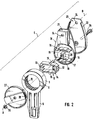
- Fig. 2 shows in detail in the form of an exploded view a swivel 5.
- This includes a first fixed hinge part 8 on which the holding and fastening part 6 is molded.
- the swivel joint 8 shows a ring 9, on which one is preferably complete circumferential internal toothing 10 is formed.
- a locking part 11 on which an external toothing 12 is formed, the combs with the internal toothing 10 and when engaged for locking the U-bracket 2 in the selected position.
- a central opening 13 provided in which a fastening pin 14 for a restoring force protruding spiral spring protrudes.
- two pins 15 are formed on the long side walls of the Locking part 11.
- the locking part 11 is in turn on a two guide walls 16 having guide device 17 of a second joint part 18 added longitudinally. There are openings in the second joint part 19 provided, through which the two pins 15 pass and on emerge from the other side of the second joint part 18. Furthermore, the second Joint part a counter bearing 20 in the form of a projecting counter bearing pin integrally formed, which is arranged for counter-bearing on the mounting pin 14 Coil spring is used. Furthermore, the second joint part has a plug receptacle 21 for the U-bracket 2.
- the second joint part 18 is during the pivoting movement of the U-bracket around the central axis A with respect to the stationary first Joint part 8 rotated and with it the locking part 11 on the second joint part 18 finally arranged with this rotatable cover 22, which is a top Leaves insertion opening 23 for the end of the release lever 7.
- This release lever 7 is with respect to the second joint part by means of a penetrating the openings 24 Screw connection, which also the U-bracket 2 in a corresponding Breakthrough penetrated, pivoted, so that the release bracket 7 something with respect to the second joint part 18 and thus also with respect to the on this fixed and immovable U-bracket 2 can be pivoted.
- a representation of the lower, flat end of the otherwise round section Release bracket 2 is shown in FIG. 5.
- the upper opening is shown on the one hand 25, of the screw connection mentioned, which forms the pivot axis B, is enforced.
- a further opening 26 is provided at the lower end, into which the upper pin 15 of the locking part 11 engages.
- a lid 27 provided, by means of which the ring 9 of the first joint part 8 is closed becomes.
- An insertion opening 28 for the rear U-bracket 3 is provided on this.
- the assembled joint connection is made using a push-through screw 29 and a lock nut 30 held together.
- Fig. 3 shows a sectional view through an assembled hinge connection 5.
- the insertion opening 28 on the cover 27 is clearly recognizable, furthermore the insertion opening 21 on the second housing part 18 and the insertion opening 23 on the rear cover 22.
- the U-bracket 2 is firmly received in the insertion opening 21, while the insertion opening 23 to enable the short pivoting movement of the release bracket 7 is dimensioned somewhat wider.
- Fig. 3 shows that Locking part 11 almost completely accommodated inside the ring 9 of the first housing part 8, so that the external toothing 12, not shown, of the latching part 11 the internal teeth 10 on the ring 9 can comb.
- the guide walls are also shown 14 of the second housing part 18, along which the locking part 11 is guided is.
- the two pins 15 it should be noted that only one Pin is sufficient - enforce the corresponding openings 19 in second housing part and emerge towards the cover, where they are flush with the inside wall of the cover complete the cover 22.
- the upper pin 15 passes through the inserted release lever 7 located opening 26 and closes to the inner wall of the cover 22, so that the pin 15 does not come out of the opening 26 can slip out.
- Fig. 4A shows the position of the locking part 11 and the U-bracket 2 and the lens bracket 7.
- the locking part 11 is due to the restoring force on this and the counter bearing pin 20 mounted coil spring 29 for internal teeth 10 of the ring 9 crowded, d. that is, the external toothing 12 of the latching part engages in the internal toothing 10 a.
- the U-bracket 2 and the release bracket 7 are common with the second joint part 8, the locking part 11 and the cover 22 can be pivoted are locked in position.
- the release lever 7 which in the preferred embodiment 1 adjacent to the U-bracket 2 on the outside of the cover 4 runs, gripped and about the pivot axis B, that of the already mentioned Screw connection is formed, pivoted in the direction of arrow C to the U-bracket 2.
- the pivoting causes the lower end of the release lever 7 is pivoted to the right in the example shown according to FIG. 4A.
- the hole-pin connection the locking part 11 of the guide walls 16 guided to the right longitudinally and out of the meshing engagement moved with the internal teeth 10.
- the release bracket 7 and the U-bracket 2 are now very close to each other.
Landscapes
- Engineering & Computer Science (AREA)
- Environmental & Geological Engineering (AREA)
- Health & Medical Sciences (AREA)
- Public Health (AREA)
- Chemical & Material Sciences (AREA)
- Combustion & Propulsion (AREA)
- Transportation (AREA)
- Mechanical Engineering (AREA)
- Carriages For Children, Sleds, And Other Hand-Operated Vehicles (AREA)
- Toys (AREA)
- Pivots And Pivotal Connections (AREA)
Abstract
Description
- Fig. 1
- eine perspektivische Ansicht eines erfindungsgemäßen Verdecks, wobei lediglich die Bügel, nicht aber die Abdeckung im Detail dargestellt ist,
- Fig. 2
- eine Sprengzeichnung eines einen Rastmechanismus aufweisenden Drehgelenks,
- Fig. 3
- eine Schnittdarstellung des zusammengesetzten, in Fig. 2 gezeigten Drehgelenks,
- Fig. 4A, 4B
- zwei Detailansichten der Eingriff- und der Lösestellung des Rastteils, und
- Fig. 5
- eine Ansicht zur Darstellung des mit dem Zapfen bewegungsgekoppelten Bereichs des Lösehebels.
Claims (15)
- Verdeck für einen Kinderwagen oder Puppenwagen, mit einer an einem U-Bügel befestigten Abdeckung, wobei der U-Bügel mit jedem seiner Enden an einem am Fahrgestell des Kinderwagens befestigten oder befestigbaren Drehgelenk gehaltert und zum Öffnen oder Schließen des Verdecks um die Gelenkachse verschwenkbar und mittels eines an wenigstens einem Drehgelenk vorgesehenen Rastmechanismus in der jeweiligen Position halterbar ist, dadurch gekennzeichnet, dass der Rastmechanismus einen ortsfesten, einen Kreis oder Kreisbogen beschreibenden Rastabschnitt mit einer Innenverzahnung (10) und ein bei Verschwenken des U-Bügels (2) bezüglich des ersten Rastabschnitts verschwenkbares Rastteil (11) mit einer mit der Innenverzahnung (10) kämmenden Außenverzahnung (12) umfasst, wobei das Rastteil (11) gegen eine in einen Rasteingriff drängende Rückstellkraft längsbeweglich geführt und zum geräuschlosen Verschwenken des Verdecks mittels eines mit dem Rastteil (11) bewegungsgekoppelten manuellen Betätigungselements aus dem Rasteingriff lösbar ist.
- Verdeck nach Anspruch 1, dadurch gekennzeichnet, dass das Betätigungselement am Drehgelenk (5) um eine Schwenkachse (B) bewegbar gelagert und mit dem Rastteil (11) über eine Loch-Zapfen-Verbindung (15, 26) bewegungsgekoppelt ist.
- Verdeck nach Anspruch 1, dadurch gekennzeichnet, dass das Betätigungselement am Drehgelenk längsbeweglich geführt und mit dem Rastteil über eine Loch-Zapfen-Verbindung bewegungsgekoppelt ist, wobei die Bewegungsachse des Betätigungselements im wesentlichen parallel zu der des Rastteils ist.
- Verdeck nach Anspruch 2 oder 3, dadurch gekennzeichnet, dass am Rastteil (11) ein vorspringender Zapfen (15) und am Betätigungselement ein den Zapfen (15) aufnehmendes Loch (26) vorgesehen ist.
- Verdeck nach Anspruch 4, dadurch gekennzeichnet, dass der Zapfen (15) mittels eines eingepressten Metallstifts verstärkt ist.
- Verdeck nach einem der vorangehenden Ansprüche, dadurch gekennzeichnet, dass das Drehgelenk (5) ein erstes ortsfestes Gelenkteil (8) mit einem das Rastteil (11) aufnehmenden Ring (9) mit der vorzugsweise umlaufenden Innenverzahnung (10) und ein über den U-Bügel (2) schwenkbares zweites Gelenkteil (18) mit einer Führungseinrichtung (17) für das separate Rastteil (11) und einer von dem Zapfen (15) des Rastteils (11) durchsetzen länglichen Durchbrechung (19) aufweist, an dem an der gegenüberliegenden Seite das Betätigungselement anliegt.
- Verdeck nach Anspruch 6, dadurch gekennzeichnet, dass das Rastteil (11) eine Aufnahme, vorzugsweise eine Durchbrechung (13), für eine die Rückstellkraft erzeugenden Feder (29), die an einem vorzugsweise zapfenförmigen Gegenlager (20) des zweiten Gelenkteils (18) gegengelagert ist, aufweist.
- Verdeck nach einem der vorangehenden Ansprüche, dadurch gekennzeichnet, dass zur Erzeugung der Rückstellkraft eine Spiralfeder (29) oder eine Blattfeder vorgesehen ist.
- Verdeck nach einem der vorangehenden Ansprüche, dadurch gekennzeichnet, dass das Drehgelenk (5) aus Kunststoff besteht.
- Verdeck nach einem der vorangehenden Ansprüche, dadurch gekennzeichnet, dass an beiden Seiten des Verdecks (1) ein Drehgelenk (5) mit einem Rastmechanismus vorgesehen ist.
- Verdeck nach einem der vorangehenden Ansprüche, dadurch gekennzeichnet, dass als Betätigungselement ein im wesentlichen parallel zum U-Bügel (2) geführter U-förmiger Lösebügel (7) vorgesehen ist, der mit je einem Ende in einem Drehgelenk (5) aufgenommen ist.
- Verdeck nach Anspruch 11, dadurch gekennzeichnet, dass der U-förmige Lösebügel (7) an der Außenseite der Abdeckung (4) geführt und an den Drehgelenken (5) schwenkgelagert ist, so dass der Lösebügel (7) zum Lösen des Rasteingriffs zum U-Bügel (2) hinzuschwenken ist.
- Verdeck nach einem der Ansprüche 1 bis 11, dadurch gekennzeichnet, dass der U-förmige Lösebügel an der Innenseite der Abdeckung und im wesentlichen direkt unterhalb des die Abdeckung tragenden U-Bügels geführt und am Drehgelenk längsbeweglich gelagert ist, so dass der Lösebügel zum Lösen des Rasteingriffs zum U-Bügel heranzuziehen ist.
- Verdeck nach einem der Ansprüche 1 bis 10, dadurch gekennzeichnet, dass an dem oder jedem einen Rastmechanismus aufweisenden Drehgelenk ein als Schwenkhebel oder Zughebel ausgebildetes Betätigungselement vorgesehen ist.
- Kinderwagen oder Puppenwagen, mit einem Verdeck nach einem der vorangehenden Ansprüche.
Priority Applications (1)
| Application Number | Priority Date | Filing Date | Title |
|---|---|---|---|
| DK00110705T DK1078841T3 (da) | 1999-08-19 | 2000-05-19 | Kaleche til en barnevogn eller dukkevogn |
Applications Claiming Priority (2)
| Application Number | Priority Date | Filing Date | Title |
|---|---|---|---|
| DE19938562 | 1999-08-19 | ||
| DE19938562A DE19938562B4 (de) | 1999-08-19 | 1999-08-19 | Verdeck für einen Kinderwagen oder Puppenwagen |
Publications (3)
| Publication Number | Publication Date |
|---|---|
| EP1078841A2 true EP1078841A2 (de) | 2001-02-28 |
| EP1078841A3 EP1078841A3 (de) | 2002-04-03 |
| EP1078841B1 EP1078841B1 (de) | 2004-12-15 |
Family
ID=7918392
Family Applications (1)
| Application Number | Title | Priority Date | Filing Date |
|---|---|---|---|
| EP00110705A Expired - Lifetime EP1078841B1 (de) | 1999-08-19 | 2000-05-19 | Verdeck für einen Kinderwagen oder Puppenwagen |
Country Status (4)
| Country | Link |
|---|---|
| EP (1) | EP1078841B1 (de) |
| AT (1) | ATE284805T1 (de) |
| DE (2) | DE19938562B4 (de) |
| DK (1) | DK1078841T3 (de) |
Cited By (3)
| Publication number | Priority date | Publication date | Assignee | Title |
|---|---|---|---|---|
| EP1642802A1 (de) * | 2004-10-01 | 2006-04-05 | Aprica Ikujikenkyukai Aprica Kassai Kabushikikaisha | Kinderwagen mit Verdeck |
| NL1037097C2 (en) * | 2009-07-03 | 2011-01-04 | Maxi Miliaan Bv | Foldable hood, stroller provided with such a foldable hood and child vehicle seat provided with such a foldable hood. |
| GB2487838A (en) * | 2011-02-01 | 2012-08-08 | Wonderland Nursery Goods | Canopy assembly for use in a child carrier apparatus and its assembly method |
Families Citing this family (1)
| Publication number | Priority date | Publication date | Assignee | Title |
|---|---|---|---|---|
| CN119858593A (zh) * | 2020-11-13 | 2025-04-22 | 明门瑞士股份有限公司 | 婴儿车 |
Family Cites Families (5)
| Publication number | Priority date | Publication date | Assignee | Title |
|---|---|---|---|---|
| US4087885A (en) * | 1977-07-05 | 1978-05-09 | Rockwell International Corporation | Adjustable hinge |
| US5190390A (en) * | 1992-01-08 | 1993-03-02 | Ming Tai Huang | Joint for connecting a canopy support to a stroller |
| US5845666A (en) * | 1996-10-25 | 1998-12-08 | Graco Children's Products Inc. | Canopy with latch and pivot members |
| GB9707630D0 (en) * | 1997-04-17 | 1997-06-04 | Britax Teutonia Kinderwagen | Baby carriage hood |
| EP0872400A3 (de) * | 1997-04-17 | 1999-08-25 | BRITAX-TEUTONIA KINDERWAGENFABRIK GmbH | Haube für Kinderwagen |
-
1999
- 1999-08-19 DE DE19938562A patent/DE19938562B4/de not_active Expired - Fee Related
-
2000
- 2000-05-19 AT AT00110705T patent/ATE284805T1/de not_active IP Right Cessation
- 2000-05-19 EP EP00110705A patent/EP1078841B1/de not_active Expired - Lifetime
- 2000-05-19 DK DK00110705T patent/DK1078841T3/da active
- 2000-05-19 DE DE50008942T patent/DE50008942D1/de not_active Expired - Lifetime
Cited By (7)
| Publication number | Priority date | Publication date | Assignee | Title |
|---|---|---|---|---|
| EP1642802A1 (de) * | 2004-10-01 | 2006-04-05 | Aprica Ikujikenkyukai Aprica Kassai Kabushikikaisha | Kinderwagen mit Verdeck |
| NL1037097C2 (en) * | 2009-07-03 | 2011-01-04 | Maxi Miliaan Bv | Foldable hood, stroller provided with such a foldable hood and child vehicle seat provided with such a foldable hood. |
| GB2487838A (en) * | 2011-02-01 | 2012-08-08 | Wonderland Nursery Goods | Canopy assembly for use in a child carrier apparatus and its assembly method |
| CN102673628A (zh) * | 2011-02-01 | 2012-09-19 | 明门香港股份有限公司 | 婴儿承载装置的顶篷组件及其组装方法 |
| GB2487838B (en) * | 2011-02-01 | 2013-06-19 | Wonderland Nursery Goods | Canopy assembly for use in a child carrier apparatus and its assembly method |
| US9004587B2 (en) | 2011-02-01 | 2015-04-14 | Wonderland Nurserygoods Company Limited | Canopy assembly for use in a child carrier apparatus and its assembly method |
| CN102673628B (zh) * | 2011-02-01 | 2015-07-01 | 明门香港股份有限公司 | 婴儿承载装置的顶篷组件及其组装方法 |
Also Published As
| Publication number | Publication date |
|---|---|
| DE19938562A1 (de) | 2001-03-01 |
| DE50008942D1 (de) | 2005-01-20 |
| DE19938562B4 (de) | 2007-04-05 |
| EP1078841A3 (de) | 2002-04-03 |
| DK1078841T3 (da) | 2005-04-04 |
| ATE284805T1 (de) | 2005-01-15 |
| EP1078841B1 (de) | 2004-12-15 |
Similar Documents
| Publication | Publication Date | Title |
|---|---|---|
| DE19729188B4 (de) | Riegeleinrichtung für Fahrzeugtüren | |
| DE3906473C2 (de) | Schließverriegelung | |
| DE102012111397B4 (de) | Motorhaubenverriegelungsvorrichtung mit Zwei-Stufen-Führung für ein Fahrzeug | |
| EP1685004B1 (de) | Ablagefach eines Kraftfahrzeuges | |
| DE60133255T2 (de) | Schliess- bzw. Öffnungssystem für Schiebetür | |
| DE3943715C2 (de) | Drehstangenverschluß | |
| DE102004018811A1 (de) | Seitensperrvorrichtung für ein Öffnungs-/Schliessglied | |
| WO2005012676A1 (de) | Kraftfahrzeugtürverschluss | |
| DE102018205680A1 (de) | Wohnwagenfenster und Öffnungsmechanismus dafür | |
| DE3617321C2 (de) | ||
| DE102017206449A1 (de) | Wohnwagenfenster und Öffnungsmechanismus dafür | |
| DE69511357T2 (de) | Elektrisch betätigtes Autotürschloss | |
| DE10162551B4 (de) | Kraftstoffeinfülldeckelverriegelung für Fahrzeuge | |
| DE10000639B4 (de) | Betätigungsvorrichtung für Schiebetür | |
| EP1881145A2 (de) | Notfallentriegelung | |
| EP1078841B1 (de) | Verdeck für einen Kinderwagen oder Puppenwagen | |
| DE60015463T2 (de) | Türgriff für Kraftfahrzeug | |
| EP1127760B1 (de) | Betätigungsvorrichtung für eine Feststellbremse | |
| DE60117932T2 (de) | Stellantrieb | |
| EP1709268B1 (de) | Stangenschloss zur montage in einem durchbruch in einer dünnen wand (indirekte klipsbefestigung) | |
| DE10118394A1 (de) | Verschlußvorrichtung | |
| EP3306016B1 (de) | Türdrücker | |
| DE3242152A1 (de) | Kofferschloss, insbesondere aktenkofferschloss | |
| EP1422121A2 (de) | Deichsel für Handgabelhubwagen | |
| EP1780355A2 (de) | Betätigungsvorrichtung für die Haube eines Kraftfahrzeuges |
Legal Events
| Date | Code | Title | Description |
|---|---|---|---|
| PUAI | Public reference made under article 153(3) epc to a published international application that has entered the european phase |
Free format text: ORIGINAL CODE: 0009012 |
|
| AK | Designated contracting states |
Kind code of ref document: A2 Designated state(s): AT BE CH CY DE DK ES FI FR GB GR IE IT LI LU MC NL PT SE |
|
| AX | Request for extension of the european patent |
Free format text: AL;LT;LV;MK;RO;SI |
|
| PUAL | Search report despatched |
Free format text: ORIGINAL CODE: 0009013 |
|
| AK | Designated contracting states |
Kind code of ref document: A3 Designated state(s): AT BE CH CY DE DK ES FI FR GB GR IE IT LI LU MC NL PT SE |
|
| AX | Request for extension of the european patent |
Free format text: AL;LT;LV;MK;RO;SI |
|
| RIC1 | Information provided on ipc code assigned before grant |
Free format text: 7B 62B 9/14 A, 7A 47C 7/66 B |
|
| 17P | Request for examination filed |
Effective date: 20020516 |
|
| AKX | Designation fees paid |
Free format text: AT BE CH CY DE DK ES FI FR GB GR IE IT LI LU MC NL PT SE |
|
| 17Q | First examination report despatched |
Effective date: 20030716 |
|
| GRAP | Despatch of communication of intention to grant a patent |
Free format text: ORIGINAL CODE: EPIDOSNIGR1 |
|
| GRAS | Grant fee paid |
Free format text: ORIGINAL CODE: EPIDOSNIGR3 |
|
| GRAA | (expected) grant |
Free format text: ORIGINAL CODE: 0009210 |
|
| AK | Designated contracting states |
Kind code of ref document: B1 Designated state(s): AT BE CH CY DE DK ES FI FR GB GR IE IT LI LU MC NL PT SE |
|
| PG25 | Lapsed in a contracting state [announced via postgrant information from national office to epo] |
Ref country code: IT Free format text: LAPSE BECAUSE OF FAILURE TO SUBMIT A TRANSLATION OF THE DESCRIPTION OR TO PAY THE FEE WITHIN THE PRESCRIBED TIME-LIMIT;WARNING: LAPSES OF ITALIAN PATENTS WITH EFFECTIVE DATE BEFORE 2007 MAY HAVE OCCURRED AT ANY TIME BEFORE 2007. THE CORRECT EFFECTIVE DATE MAY BE DIFFERENT FROM THE ONE RECORDED. Effective date: 20041215 Ref country code: IE Free format text: LAPSE BECAUSE OF FAILURE TO SUBMIT A TRANSLATION OF THE DESCRIPTION OR TO PAY THE FEE WITHIN THE PRESCRIBED TIME-LIMIT Effective date: 20041215 Ref country code: FR Free format text: LAPSE BECAUSE OF FAILURE TO SUBMIT A TRANSLATION OF THE DESCRIPTION OR TO PAY THE FEE WITHIN THE PRESCRIBED TIME-LIMIT Effective date: 20041215 Ref country code: GB Free format text: LAPSE BECAUSE OF FAILURE TO SUBMIT A TRANSLATION OF THE DESCRIPTION OR TO PAY THE FEE WITHIN THE PRESCRIBED TIME-LIMIT Effective date: 20041215 |
|
| REG | Reference to a national code |
Ref country code: CH Ref legal event code: EP Ref country code: GB Ref legal event code: FG4D Free format text: NOT ENGLISH Ref country code: CH Ref legal event code: NV Representative=s name: ISLER & PEDRAZZINI AG |
|
| REG | Reference to a national code |
Ref country code: IE Ref legal event code: FG4D Free format text: GERMAN |
|
| REF | Corresponds to: |
Ref document number: 50008942 Country of ref document: DE Date of ref document: 20050120 Kind code of ref document: P |
|
| REG | Reference to a national code |
Ref country code: SE Ref legal event code: TRGR |
|
| PG25 | Lapsed in a contracting state [announced via postgrant information from national office to epo] |
Ref country code: GR Free format text: LAPSE BECAUSE OF FAILURE TO SUBMIT A TRANSLATION OF THE DESCRIPTION OR TO PAY THE FEE WITHIN THE PRESCRIBED TIME-LIMIT Effective date: 20050315 |
|
| PG25 | Lapsed in a contracting state [announced via postgrant information from national office to epo] |
Ref country code: ES Free format text: LAPSE BECAUSE OF FAILURE TO SUBMIT A TRANSLATION OF THE DESCRIPTION OR TO PAY THE FEE WITHIN THE PRESCRIBED TIME-LIMIT Effective date: 20050326 |
|
| REG | Reference to a national code |
Ref country code: DK Ref legal event code: T3 |
|
| PGFP | Annual fee paid to national office [announced via postgrant information from national office to epo] |
Ref country code: FI Payment date: 20050503 Year of fee payment: 6 |
|
| PG25 | Lapsed in a contracting state [announced via postgrant information from national office to epo] |
Ref country code: CY Free format text: LAPSE BECAUSE OF FAILURE TO SUBMIT A TRANSLATION OF THE DESCRIPTION OR TO PAY THE FEE WITHIN THE PRESCRIBED TIME-LIMIT Effective date: 20050519 Ref country code: LU Free format text: LAPSE BECAUSE OF NON-PAYMENT OF DUE FEES Effective date: 20050519 |
|
| PGFP | Annual fee paid to national office [announced via postgrant information from national office to epo] |
Ref country code: BE Payment date: 20050523 Year of fee payment: 6 |
|
| PGFP | Annual fee paid to national office [announced via postgrant information from national office to epo] |
Ref country code: CH Payment date: 20050524 Year of fee payment: 6 |
|
| PG25 | Lapsed in a contracting state [announced via postgrant information from national office to epo] |
Ref country code: MC Free format text: LAPSE BECAUSE OF NON-PAYMENT OF DUE FEES Effective date: 20050531 |
|
| GBV | Gb: ep patent (uk) treated as always having been void in accordance with gb section 77(7)/1977 [no translation filed] |
Effective date: 20041215 |
|
| REG | Reference to a national code |
Ref country code: IE Ref legal event code: FD4D |
|
| PLBE | No opposition filed within time limit |
Free format text: ORIGINAL CODE: 0009261 |
|
| STAA | Information on the status of an ep patent application or granted ep patent |
Free format text: STATUS: NO OPPOSITION FILED WITHIN TIME LIMIT |
|
| 26N | No opposition filed |
Effective date: 20050916 |
|
| EN | Fr: translation not filed | ||
| PG25 | Lapsed in a contracting state [announced via postgrant information from national office to epo] |
Ref country code: FI Free format text: LAPSE BECAUSE OF NON-PAYMENT OF DUE FEES Effective date: 20060519 |
|
| PG25 | Lapsed in a contracting state [announced via postgrant information from national office to epo] |
Ref country code: BE Free format text: LAPSE BECAUSE OF NON-PAYMENT OF DUE FEES Effective date: 20060531 Ref country code: CH Free format text: LAPSE BECAUSE OF NON-PAYMENT OF DUE FEES Effective date: 20060531 Ref country code: LI Free format text: LAPSE BECAUSE OF NON-PAYMENT OF DUE FEES Effective date: 20060531 |
|
| REG | Reference to a national code |
Ref country code: CH Ref legal event code: PL |
|
| BERE | Be: lapsed |
Owner name: JOH. GEORG *HARTAN Effective date: 20060531 |
|
| PG25 | Lapsed in a contracting state [announced via postgrant information from national office to epo] |
Ref country code: PT Free format text: LAPSE BECAUSE OF NON-PAYMENT OF DUE FEES Effective date: 20050515 |
|
| PGFP | Annual fee paid to national office [announced via postgrant information from national office to epo] |
Ref country code: DK Payment date: 20090526 Year of fee payment: 10 Ref country code: NL Payment date: 20090529 Year of fee payment: 10 |
|
| PGFP | Annual fee paid to national office [announced via postgrant information from national office to epo] |
Ref country code: AT Payment date: 20090427 Year of fee payment: 10 |
|
| REG | Reference to a national code |
Ref country code: NL Ref legal event code: V1 Effective date: 20101201 |
|
| REG | Reference to a national code |
Ref country code: DK Ref legal event code: EBP |
|
| PG25 | Lapsed in a contracting state [announced via postgrant information from national office to epo] |
Ref country code: AT Free format text: LAPSE BECAUSE OF NON-PAYMENT OF DUE FEES Effective date: 20100519 |
|
| PG25 | Lapsed in a contracting state [announced via postgrant information from national office to epo] |
Ref country code: NL Free format text: LAPSE BECAUSE OF NON-PAYMENT OF DUE FEES Effective date: 20101201 |
|
| PG25 | Lapsed in a contracting state [announced via postgrant information from national office to epo] |
Ref country code: DK Free format text: LAPSE BECAUSE OF NON-PAYMENT OF DUE FEES Effective date: 20100531 |
|
| PGFP | Annual fee paid to national office [announced via postgrant information from national office to epo] |
Ref country code: SE Payment date: 20110517 Year of fee payment: 12 |
|
| REG | Reference to a national code |
Ref country code: SE Ref legal event code: EUG |
|
| PG25 | Lapsed in a contracting state [announced via postgrant information from national office to epo] |
Ref country code: SE Free format text: LAPSE BECAUSE OF NON-PAYMENT OF DUE FEES Effective date: 20120520 |
|
| PGFP | Annual fee paid to national office [announced via postgrant information from national office to epo] |
Ref country code: DE Payment date: 20160512 Year of fee payment: 17 |
|
| REG | Reference to a national code |
Ref country code: DE Ref legal event code: R119 Ref document number: 50008942 Country of ref document: DE |
|
| PG25 | Lapsed in a contracting state [announced via postgrant information from national office to epo] |
Ref country code: DE Free format text: LAPSE BECAUSE OF NON-PAYMENT OF DUE FEES Effective date: 20171201 |