EP1075392B1 - Cartouche perfectionnee de produit consommable pour imprimante - Google Patents
Cartouche perfectionnee de produit consommable pour imprimante Download PDFInfo
- Publication number
- EP1075392B1 EP1075392B1 EP99916964A EP99916964A EP1075392B1 EP 1075392 B1 EP1075392 B1 EP 1075392B1 EP 99916964 A EP99916964 A EP 99916964A EP 99916964 A EP99916964 A EP 99916964A EP 1075392 B1 EP1075392 B1 EP 1075392B1
- Authority
- EP
- European Patent Office
- Prior art keywords
- cartridge
- printer
- chip
- data
- consumable item
- Prior art date
- Legal status (The legal status is an assumption and is not a legal conclusion. Google has not performed a legal analysis and makes no representation as to the accuracy of the status listed.)
- Expired - Lifetime
Links
Images
Classifications
-
- B—PERFORMING OPERATIONS; TRANSPORTING
- B41—PRINTING; LINING MACHINES; TYPEWRITERS; STAMPS
- B41J—TYPEWRITERS; SELECTIVE PRINTING MECHANISMS, i.e. MECHANISMS PRINTING OTHERWISE THAN FROM A FORME; CORRECTION OF TYPOGRAPHICAL ERRORS
- B41J2/00—Typewriters or selective printing mechanisms characterised by the printing or marking process for which they are designed
- B41J2/005—Typewriters or selective printing mechanisms characterised by the printing or marking process for which they are designed characterised by bringing liquid or particles selectively into contact with a printing material
- B41J2/01—Ink jet
- B41J2/17—Ink jet characterised by ink handling
- B41J2/175—Ink supply systems ; Circuit parts therefor
- B41J2/17503—Ink cartridges
- B41J2/17543—Cartridge presence detection or type identification
- B41J2/17546—Cartridge presence detection or type identification electronically
-
- B—PERFORMING OPERATIONS; TRANSPORTING
- B41—PRINTING; LINING MACHINES; TYPEWRITERS; STAMPS
- B41J—TYPEWRITERS; SELECTIVE PRINTING MECHANISMS, i.e. MECHANISMS PRINTING OTHERWISE THAN FROM A FORME; CORRECTION OF TYPOGRAPHICAL ERRORS
- B41J17/00—Mechanisms for manipulating page-width impression-transfer material, e.g. carbon paper
- B41J17/36—Alarms, indicators, or feed-disabling devices responsible to material breakage or exhaustion
-
- B—PERFORMING OPERATIONS; TRANSPORTING
- B41—PRINTING; LINING MACHINES; TYPEWRITERS; STAMPS
- B41J—TYPEWRITERS; SELECTIVE PRINTING MECHANISMS, i.e. MECHANISMS PRINTING OTHERWISE THAN FROM A FORME; CORRECTION OF TYPOGRAPHICAL ERRORS
- B41J35/00—Other apparatus or arrangements associated with, or incorporated in, ink-ribbon mechanisms
- B41J35/36—Alarms, indicators, or feed disabling devices responsive to ink ribbon breakage or exhaustion
-
- G—PHYSICS
- G03—PHOTOGRAPHY; CINEMATOGRAPHY; ANALOGOUS TECHNIQUES USING WAVES OTHER THAN OPTICAL WAVES; ELECTROGRAPHY; HOLOGRAPHY
- G03G—ELECTROGRAPHY; ELECTROPHOTOGRAPHY; MAGNETOGRAPHY
- G03G15/00—Apparatus for electrographic processes using a charge pattern
- G03G15/06—Apparatus for electrographic processes using a charge pattern for developing
- G03G15/08—Apparatus for electrographic processes using a charge pattern for developing using a solid developer, e.g. powder developer
- G03G15/0822—Arrangements for preparing, mixing, supplying or dispensing developer
- G03G15/0848—Arrangements for testing or measuring developer properties or quality, e.g. charge, size, flowability
- G03G15/0849—Detection or control means for the developer concentration
- G03G15/0855—Detection or control means for the developer concentration the concentration being measured by optical means
-
- G—PHYSICS
- G03—PHOTOGRAPHY; CINEMATOGRAPHY; ANALOGOUS TECHNIQUES USING WAVES OTHER THAN OPTICAL WAVES; ELECTROGRAPHY; HOLOGRAPHY
- G03G—ELECTROGRAPHY; ELECTROPHOTOGRAPHY; MAGNETOGRAPHY
- G03G15/00—Apparatus for electrographic processes using a charge pattern
- G03G15/06—Apparatus for electrographic processes using a charge pattern for developing
- G03G15/08—Apparatus for electrographic processes using a charge pattern for developing using a solid developer, e.g. powder developer
- G03G15/0822—Arrangements for preparing, mixing, supplying or dispensing developer
- G03G15/0863—Arrangements for preparing, mixing, supplying or dispensing developer provided with identifying means or means for storing process- or use parameters, e.g. an electronic memory
-
- G—PHYSICS
- G03—PHOTOGRAPHY; CINEMATOGRAPHY; ANALOGOUS TECHNIQUES USING WAVES OTHER THAN OPTICAL WAVES; ELECTROGRAPHY; HOLOGRAPHY
- G03G—ELECTROGRAPHY; ELECTROPHOTOGRAPHY; MAGNETOGRAPHY
- G03G15/00—Apparatus for electrographic processes using a charge pattern
- G03G15/06—Apparatus for electrographic processes using a charge pattern for developing
- G03G15/08—Apparatus for electrographic processes using a charge pattern for developing using a solid developer, e.g. powder developer
- G03G15/0822—Arrangements for preparing, mixing, supplying or dispensing developer
- G03G15/0865—Arrangements for supplying new developer
Definitions
- the present invention relates to a cartridge of consumable product for printer, such as powder, or toner, for printing for printer laser or printing ribbon by thermal ink transfer.
- thermal transfer is meant any transfer process of the ink of a ribbon by means of a thermal source, including therefore the sublimation process.
- this includes a drum electrostatic developer on which is formed, by a charged roller electrically, a layer of electric charges.
- the laser scans each generator that passes to form an image latent according to the data that command it.
- the generators of the roller then pass next to a pigment or toner cartridge, particles of it are attracted to the remaining charges and the image latent is thus revealed so that its pigment particles are deposited gradually on a leaf moving against a regenerator of the roller.
- An oven then penetrates the toner into the paper to fix it definitively, after regulation of the thickness of pigment by a blade with adjustable potential.
- the image quality depends on all the settings of the various voltages of the above elements and the oven temperature, depending the type of pigment, its manufacturer, and the manufacturer of the printer.
- this optimal set of settings varies depending on the percentage of pigment remaining in the cassette containing it.
- the printer automatically prints a test pattern and an optical sensor determines the quality of the result obtained, for empirically determine a substantially optimal set of settings.
- the sensor only provides relatively poor information, given the number of setting parameters, so the setting overall is only rough and does not offer any guarantee of long-term reliability term.
- the thermal source of the printer using plain paper and a ribbon thermal transfer, includes a writing head comprising a plurality of heating elements electrically controlled by logical information.
- the print quality depends directly on the characteristics of control of the thermal head including, in particular, the characteristics of the printing ribbon.
- US-A-5,491,540 teaches a cartridge of consumable product for printer with a data memory card, specifying the product characteristics, which can be connected by a connector to a printer controller.
- the invention relates to a cartridge of consumable product for printers, comprising an electronic chip for storing technical data characteristic of the consumable product and print command, the chip being arranged to be read, cartridge characterized in that the storage chip is arranged on a support card removable and is arranged for downloading data techniques.
- storage chip contains data adjusting the tension of at least one printing roller and the temperature of a toner baking oven.
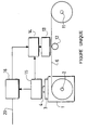
- the ribbon cartridge referenced 1 is shown mounted in a fax. It has a hub 2 carrying a roll of ribbon printing 6, ribbon which is received on a receiving hub 11 after passage between a thermal printing head 13 and a roll of counter-support 12, with a sheet of paper to be printed, not shown.
- the cartridge 1 carries, on an accessible face, a circuit 3 for entering technical data characteristics of ribbon 6 and control printing head 13.
- Circuit 3 is here a card carrying a chip electronic 4 which cooperates, through contact areas on the card 3, with a connector 15 of the printer connected to a logic 14 for controlling the head 13.
- the smart card 3 can thus be read by this logic 14 for that it enters, in the memory of chip 4, the parameters or control features of the head 13, such as the ink type of the ribbon 6, mentioned at the beginning.
- Chip card 3 therefore performs storage control data and offers their reading by logic 14.
- Data entry chip 4 can be placed on a support card removable like a smart card and, in this case, the user plate or introduces the capture smart card (3, 4), on or in a connector (15) can then be integrated into logic 14.
- provision may be made to enter all or part command data from head 13 by downloading these data from a server.
- chip 4 can control the interface 16, via the connector 15, to establish a connection with the server, in order to download the logic 14 by the data appropriate for the ribbon of cartridge 1.
- the chip 4 sends the server call number online then, the communication established, it sends it data identifying the type of cartridge, such as than a reference number. This number is used as the internal address of the server to select the appropriate head control data 13 and the send back to logic 14, through interface 16.
- smart card 3 is associated with a pigment cartridge toner.
- Chip card order data 3 then include various control sets for adjusting the voltages of various rollers or drum mentioned at the beginning and the temperature of the oven, depending on the pigment of the cassette. The influence of humidity can also be modeled and taken into account from the readings of a sensor.
- the logic 14 includes a microprocessor associated with a memory containing data identifying the type of the printer. Logic 14 thus selects the command set, the smart card 3, which concerns the printer.
- the smart card 3 includes, for each set of commands, several data blocks, or tables, each representing the game optimal depending on the emptying rate of the pigment cassette, by example originally, after a thousand impressions and after two thousand impressions.
- Logic 14 counts the number of prints and thus updates day of the optimal set of parameters, possibly by interpolation between two successive games.
- the smart card 3 having from the outset provided the identity of the cassette to the logic 14, and therefore its capacity in number of impressions, logic 14 controls the display of a corresponding alarm message on a screen fax machine, when the cassette is almost used up.
- chip 4 which, in addition to the data storage for intelligent management of settings, performs the tasks, outlined above, of logic 14. Intelligence is therefore almost entirely in the smart card 3, as far as concerns the settings, logic 14 only retransmitting the adjustments to the slave elements and providing information to the card to chip 3. This kind of smart control from smart card 3 is also valid for any other consumable product, to ensure improved, optimal printer management.
Landscapes
- Physics & Mathematics (AREA)
- General Physics & Mathematics (AREA)
- Accessory Devices And Overall Control Thereof (AREA)
Description
- son type : à encre noire, à encre de couleur, monochrome ou à plages de couleur multiples, par transfert thermique stricto sensu ou par sublimation, métallisé ou autres,
- la plage de couleur à l'instant d'impression,
- la couleur de la plage,
- le niveau dans la plage à l'instant d'impression,
- le début de la plage considérée,
- le niveau dans le ruban à l'instant d'impression,
- la définition des couleurs des plages du ruban.
Claims (4)
- Cartouche (1) de produit consommable (6) pour imprimante, comportant une puce électronique (4) de stockage de données techniques caractéristiques du produit consommable (6) et de commande d'impression (14), la puce (4) étant agencée pour être lue, cartouche caractérisée par le fait que la puce de stockage (4) est disposée sur une carte-support amovible (3) et est agencée pour le téléchargement des données techniques.
- Cartouche selon la revendication 1, dans laquelle, le produit consommable étant du toner, la puce de stockage (4) comporte des données de réglage de la tension d'au moins un rouleau d'impression.
- Cartouche selon la revendication 2, dans laquelle la puce de stockage (4) comporte des données de réglage de la température d'un four de cuisson du toner.
- Cartouche selon l'une des revendications 2 et 3, dans laquelle les données de réglage de la puce (4) sont associées à divers taux de remplissage en toner de la cartouche.
Applications Claiming Priority (3)
| Application Number | Priority Date | Filing Date | Title |
|---|---|---|---|
| FR9805517 | 1998-04-30 | ||
| FR9805517A FR2778142B1 (fr) | 1998-04-30 | 1998-04-30 | Cartouche perfectionnee de produit consommable pour imprimante |
| PCT/FR1999/001032 WO1999056962A1 (fr) | 1998-04-30 | 1999-04-30 | Cartouche perfectionnee de produit consommable pour imprimante |
Publications (2)
| Publication Number | Publication Date |
|---|---|
| EP1075392A1 EP1075392A1 (fr) | 2001-02-14 |
| EP1075392B1 true EP1075392B1 (fr) | 2002-03-20 |
Family
ID=9525922
Family Applications (1)
| Application Number | Title | Priority Date | Filing Date |
|---|---|---|---|
| EP99916964A Expired - Lifetime EP1075392B1 (fr) | 1998-04-30 | 1999-04-30 | Cartouche perfectionnee de produit consommable pour imprimante |
Country Status (5)
| Country | Link |
|---|---|
| US (1) | US6522348B1 (fr) |
| EP (1) | EP1075392B1 (fr) |
| DE (1) | DE69901059T2 (fr) |
| FR (1) | FR2778142B1 (fr) |
| WO (1) | WO1999056962A1 (fr) |
Families Citing this family (15)
| Publication number | Priority date | Publication date | Assignee | Title |
|---|---|---|---|---|
| US6724895B1 (en) | 1998-06-18 | 2004-04-20 | Supersensor (Proprietary) Limited | Electronic identification system and method with source authenticity verification |
| JP2002321392A (ja) * | 2001-03-02 | 2002-11-05 | Oce Technologies Bv | プリンタおよびインクカートリッジの構成方法 |
| US20020149785A1 (en) * | 2001-03-30 | 2002-10-17 | Chia-Lin Chu | Automatic printer color correction based on characterization data of a color ink cartridge |
| US7221473B2 (en) * | 2001-08-03 | 2007-05-22 | Hewlett-Packard Development Company, L.P. | Printing system for updating printing characteristics with a printing consumable |
| US7137000B2 (en) * | 2001-08-24 | 2006-11-14 | Zih Corp. | Method and apparatus for article authentication |
| AUPS048202A0 (en) * | 2002-02-13 | 2002-03-07 | Silverbrook Research Pty. Ltd. | Methods and systems (ap78) |
| JP2003289416A (ja) * | 2002-03-28 | 2003-10-10 | Brother Ind Ltd | 通信システム、端末装置およびセンタ装置 |
| US9296214B2 (en) | 2004-07-02 | 2016-03-29 | Zih Corp. | Thermal print head usage monitor and method for using the monitor |
| US7344212B2 (en) | 2004-08-16 | 2008-03-18 | Lexmark International, Inc. | Imaging apparatus having a programmable throughput rate |
| JP4319176B2 (ja) * | 2005-08-23 | 2009-08-26 | シャープ株式会社 | 顧客交換可能ユニットを含むネットワークシステム |
| US8721203B2 (en) * | 2005-10-06 | 2014-05-13 | Zih Corp. | Memory system and method for consumables of a printer |
| US9098216B2 (en) | 2012-04-25 | 2015-08-04 | Hewlett-Packard Development Company, L.P. | Printer functionality enablement |
| EP4234254A3 (fr) | 2013-07-31 | 2023-09-13 | Hewlett-Packard Development Company, L.P. | Protection de données dans la mémoire d'un produit consommable |
| US10592289B2 (en) | 2014-10-31 | 2020-03-17 | Hewlett-Packard Development Company, L.P. | Providing auxiliary services or functionality on an apparatus |
| JP6596390B2 (ja) * | 2016-06-29 | 2019-10-23 | 株式会社沖データ | 現像剤収容器、現像装置、画像形成装置、及び基板支持構造 |
Family Cites Families (12)
| Publication number | Priority date | Publication date | Assignee | Title |
|---|---|---|---|---|
| FR2566327B1 (fr) * | 1984-06-25 | 1989-06-02 | Epson Corp | Imprimante |
| DE3718013C1 (de) * | 1987-05-27 | 1988-11-10 | Triumph Adler Ag | Farbbandkassette fuer elektronisch gesteuerte Schreib- oder aehnliche Bueromaschinen |
| US5087137A (en) * | 1988-07-19 | 1992-02-11 | Datamax Corporation | Ribbon assembly including indicia to identify operating parameters and ribbon depletion |
| US4961088A (en) * | 1989-04-20 | 1990-10-02 | Xerox Corporation | Monitor/warranty system for electrostatographic reproducing machines using replaceable cartridges |
| US5035325A (en) * | 1989-07-18 | 1991-07-30 | Dai Nippon Insatsu Kabushiki Kaisha | Cassette for thermal transfer printing film |
| GB9119483D0 (en) * | 1991-09-11 | 1991-10-23 | Xerox Corp | Replaceable sub-assemblies for electrostatographic reproducing machines |
| EP0586265A1 (fr) * | 1992-06-24 | 1994-03-09 | Axiohm | Dispositif d'enregistrement des opérations d'une imprimante thermique à transfert |
| FR2706655B1 (fr) * | 1993-06-17 | 1995-08-25 | Gemplus Card Int | Procédé de contrôle d'une imprimante pour obtenir des affranchissements postaux. |
| WO1995024316A1 (fr) * | 1994-03-07 | 1995-09-14 | Xerox Corporation | Ruban encreur code pour imprimante et son mode d'utilisation |
| US5491540A (en) * | 1994-12-22 | 1996-02-13 | Hewlett-Packard Company | Replacement part with integral memory for usage and calibration data |
| KR100413780B1 (ko) * | 1996-01-19 | 2004-03-22 | 다이니폰 인사츠 가부시키가이샤 | 잉크리본및서멀프린터 |
| US6144812A (en) * | 1998-03-20 | 2000-11-07 | Canon Kabushiki Kaisha | Image formation system having a memory device located in an electrophotographic process cartridge for storing data relating to image formation |
-
1998
- 1998-04-30 FR FR9805517A patent/FR2778142B1/fr not_active Expired - Fee Related
-
1999
- 1999-04-30 DE DE69901059T patent/DE69901059T2/de not_active Expired - Lifetime
- 1999-04-30 WO PCT/FR1999/001032 patent/WO1999056962A1/fr not_active Ceased
- 1999-04-30 US US09/674,166 patent/US6522348B1/en not_active Expired - Lifetime
- 1999-04-30 EP EP99916964A patent/EP1075392B1/fr not_active Expired - Lifetime
Also Published As
| Publication number | Publication date |
|---|---|
| FR2778142B1 (fr) | 2000-06-09 |
| US6522348B1 (en) | 2003-02-18 |
| WO1999056962A1 (fr) | 1999-11-11 |
| EP1075392A1 (fr) | 2001-02-14 |
| DE69901059D1 (de) | 2002-04-25 |
| FR2778142A1 (fr) | 1999-11-05 |
| DE69901059T2 (de) | 2002-11-28 |
Similar Documents
| Publication | Publication Date | Title |
|---|---|---|
| FR2778142A1 (fr) | Cartouche perfectionnee de produit consommable pour imprimante | |
| EP0743568B1 (fr) | Pièce de rechange à mémoire intégrée pour des données d'utilisation et de calibration | |
| EP0789322B1 (fr) | Pièce de rechange à mémoire intégrée pour des données d'usage, de calibration et autres | |
| CN101105656B (zh) | 图像形成设备 | |
| EP0813120B1 (fr) | Ensemble imprimante et son réservoir de consommable pour machine de bureau | |
| JP4781191B2 (ja) | 画像形成装置および画像形成方法 | |
| FR2507127A1 (fr) | Imprimante a transfert thermique pour imprimer des images sur du papier normal | |
| US7248382B2 (en) | Media parameter downloading | |
| EP0029313B1 (fr) | Imprimante thermique | |
| FR2732127A1 (fr) | Appareil de formation d'images | |
| JP2008129056A (ja) | 画像形成装置 | |
| US8483590B2 (en) | Method and apparatus for external heater roll cleaning | |
| FR2601539A1 (fr) | Appareil de telecopie dote d'une memoire d'information sur le papier d'enregistrement | |
| US7184180B2 (en) | Image forming apparatus, image forming method and program, and recording medium | |
| KR100706673B1 (ko) | 고속 사진인쇄장치 | |
| US5937257A (en) | Retractable oil reducing metering blade | |
| JPS63121873A (ja) | ハイライトカラー文書の形成に使用するトナー粒子の濃度制御装置及び方法 | |
| US20240362447A1 (en) | Image-forming system, method, image-forming apparatus, and server apparatus | |
| US7796900B2 (en) | Developer cartridge replacement scheme for electrostatographic printing | |
| US20050280691A1 (en) | Printer | |
| GB2433471A (en) | Cleaning system for a fuser apparatus | |
| US20060268040A1 (en) | Image forming system, image forming apparatus and image forming method | |
| EP0864934B1 (fr) | Appareil d'enregistrement à tête de flux ionique et à développement liquide | |
| EP1304601B1 (fr) | Méthode de formation d'image et appareil de formation d'image | |
| FR2793443A1 (fr) | Machine de bureau a approvisionnement automatique en produit consommable |
Legal Events
| Date | Code | Title | Description |
|---|---|---|---|
| PUAI | Public reference made under article 153(3) epc to a published international application that has entered the european phase |
Free format text: ORIGINAL CODE: 0009012 |
|
| 17P | Request for examination filed |
Effective date: 20001128 |
|
| AK | Designated contracting states |
Kind code of ref document: A1 Designated state(s): DE GB |
|
| GRAG | Despatch of communication of intention to grant |
Free format text: ORIGINAL CODE: EPIDOS AGRA |
|
| 17Q | First examination report despatched |
Effective date: 20010607 |
|
| GRAG | Despatch of communication of intention to grant |
Free format text: ORIGINAL CODE: EPIDOS AGRA |
|
| GRAH | Despatch of communication of intention to grant a patent |
Free format text: ORIGINAL CODE: EPIDOS IGRA |
|
| REG | Reference to a national code |
Ref country code: GB Ref legal event code: IF02 |
|
| GRAH | Despatch of communication of intention to grant a patent |
Free format text: ORIGINAL CODE: EPIDOS IGRA |
|
| GRAA | (expected) grant |
Free format text: ORIGINAL CODE: 0009210 |
|
| AK | Designated contracting states |
Kind code of ref document: B1 Designated state(s): DE GB |
|
| REF | Corresponds to: |
Ref document number: 69901059 Country of ref document: DE Date of ref document: 20020425 |
|
| PLBE | No opposition filed within time limit |
Free format text: ORIGINAL CODE: 0009261 |
|
| STAA | Information on the status of an ep patent application or granted ep patent |
Free format text: STATUS: NO OPPOSITION FILED WITHIN TIME LIMIT |
|
| 26N | No opposition filed |
Effective date: 20021223 |
|
| REG | Reference to a national code |
Ref country code: GB Ref legal event code: 732E Free format text: REGISTERED BETWEEN 20090319 AND 20090325 |
|
| REG | Reference to a national code |
Ref country code: GB Ref legal event code: 732E Free format text: REGISTERED BETWEEN 20090326 AND 20090401 |
|
| REG | Reference to a national code |
Ref country code: DE Ref legal event code: R082 Ref document number: 69901059 Country of ref document: DE Ref country code: DE Ref legal event code: R082 Ref document number: 69901059 Country of ref document: DE Representative=s name: , |
|
| REG | Reference to a national code |
Ref country code: DE Ref legal event code: R081 Ref document number: 69901059 Country of ref document: DE Owner name: SAGEMCOM SAS, FR Free format text: FORMER OWNER: SAGEM S.A., PARIS, FR Effective date: 20120120 |
|
| REG | Reference to a national code |
Ref country code: DE Ref legal event code: R081 Ref document number: 69901059 Country of ref document: DE Owner name: SAGEMCOM SAS, FR Free format text: FORMER OWNER: SAGEM TELECOMMUNICATIONS S. A., PARIS, FR Effective date: 20130129 |
|
| PGFP | Annual fee paid to national office [announced via postgrant information from national office to epo] |
Ref country code: GB Payment date: 20150324 Year of fee payment: 17 |
|
| PGFP | Annual fee paid to national office [announced via postgrant information from national office to epo] |
Ref country code: DE Payment date: 20150319 Year of fee payment: 17 |
|
| REG | Reference to a national code |
Ref country code: DE Ref legal event code: R119 Ref document number: 69901059 Country of ref document: DE |
|
| GBPC | Gb: european patent ceased through non-payment of renewal fee |
Effective date: 20160430 |
|
| PG25 | Lapsed in a contracting state [announced via postgrant information from national office to epo] |
Ref country code: DE Free format text: LAPSE BECAUSE OF NON-PAYMENT OF DUE FEES Effective date: 20161101 Ref country code: GB Free format text: LAPSE BECAUSE OF NON-PAYMENT OF DUE FEES Effective date: 20160430 |