EP1074850A2 - Prüfkreis für die synthetische Prüfung des Einschaltvermögens von Hochspannungsschaltgeräten - Google Patents
Prüfkreis für die synthetische Prüfung des Einschaltvermögens von Hochspannungsschaltgeräten Download PDFInfo
- Publication number
- EP1074850A2 EP1074850A2 EP00810502A EP00810502A EP1074850A2 EP 1074850 A2 EP1074850 A2 EP 1074850A2 EP 00810502 A EP00810502 A EP 00810502A EP 00810502 A EP00810502 A EP 00810502A EP 1074850 A2 EP1074850 A2 EP 1074850A2
- Authority
- EP
- European Patent Office
- Prior art keywords
- circuit
- voltage
- test
- auxiliary switch
- current source
- Prior art date
- Legal status (The legal status is an assumption and is not a legal conclusion. Google has not performed a legal analysis and makes no representation as to the accuracy of the status listed.)
- Withdrawn
Links
- 238000012360 testing method Methods 0.000 title claims abstract description 82
- 239000004065 semiconductor Substances 0.000 claims description 16
- 239000003990 capacitor Substances 0.000 claims 2
- 230000009471 action Effects 0.000 description 10
- 230000003993 interaction Effects 0.000 description 3
- 230000008878 coupling Effects 0.000 description 2
- 238000010168 coupling process Methods 0.000 description 2
- 238000005859 coupling reaction Methods 0.000 description 2
- 238000012423 maintenance Methods 0.000 description 2
- 230000004913 activation Effects 0.000 description 1
- 230000008033 biological extinction Effects 0.000 description 1
- 230000001419 dependent effect Effects 0.000 description 1
- 230000000694 effects Effects 0.000 description 1
- 230000005611 electricity Effects 0.000 description 1
- 230000003628 erosive effect Effects 0.000 description 1
- 230000001681 protective effect Effects 0.000 description 1
- 230000035939 shock Effects 0.000 description 1
- 230000007704 transition Effects 0.000 description 1
Images



Classifications
-
- G—PHYSICS
- G01—MEASURING; TESTING
- G01R—MEASURING ELECTRIC VARIABLES; MEASURING MAGNETIC VARIABLES
- G01R31/00—Arrangements for testing electric properties; Arrangements for locating electric faults; Arrangements for electrical testing characterised by what is being tested not provided for elsewhere
- G01R31/327—Testing of circuit interrupters, switches or circuit-breakers
- G01R31/333—Testing of the switching capacity of high-voltage circuit-breakers ; Testing of breaking capacity or related variables, e.g. post arc current or transient recovery voltage
- G01R31/3333—Apparatus, systems or circuits therefor
- G01R31/3336—Synthetic testing, i.e. with separate current and voltage generators simulating distance fault conditions
-
- G—PHYSICS
- G01—MEASURING; TESTING
- G01R—MEASURING ELECTRIC VARIABLES; MEASURING MAGNETIC VARIABLES
- G01R31/00—Arrangements for testing electric properties; Arrangements for locating electric faults; Arrangements for electrical testing characterised by what is being tested not provided for elsewhere
- G01R31/327—Testing of circuit interrupters, switches or circuit-breakers
Definitions
- the invention is based on a test group according to the Preamble of claim 1 or claim 5.
- a test circuit is known from the published patent application DE 3 732 163 A1 for the synthetic test of the switching capacity of Circuit breakers known.
- the one to be checked Switch-on voltage acting on the circuit breaker is determined by provided a high voltage circuit, the corresponding Inrush current from a high current circuit.
- a Auxiliary switch which is designed here as a spark gap, the high current circuit after the pre-ignition of the test Circuit breaker on it, so that the Circuit breaker with the one that corresponds to reality Inrush current is loaded.
- the rapid switching of this Spark gap can only be achieved by means of a comparatively large one Effort on sensors and wiring can be achieved.
- the invention as set out in the independent claims is marked, solves the task of a test group for the synthetic test of the switch-on capacity of To create high-voltage switchgear, the easier is built that is easier to operate and one has improved operational availability.
- the test group for the synthetic test of The breaking capacity of high-voltage switchgear is included one a high current source and one to be tested High-voltage switching device having high current circuit and with a parallel to the high-voltage switchgear to be tested provided lying high voltage circuit, furthermore with means for switching on the high current source to the one to be tested High voltage switchgear.
- the means for switching on the High current sources include in a first embodiment at least two auxiliary switches connected in series, the first auxiliary switch on the one facing the high current source Side of the second auxiliary switch is arranged. Parallel to second auxiliary switch, a diode circuit is provided, which currents to block towards the high current source.
- the Means for connecting the high current source at least an auxiliary switch and one connected in parallel to this Arrangement of controlled semiconductor elements.
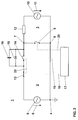
- Test circuit 1 shows a greatly simplified test circuit 1 for the test of the switch - on capacity of High-voltage switching devices, such as Circuit breakers or disconnectors.
- the test circle 1 sits down together from a high current circuit 2 and one High-voltage circuit 3.
- Test circuit 1 is at a terminal 4 rigidly grounded.
- the high current circuit 2 is fed by a Generator 5, which supplies a generator voltage 6, which in the Usually lies in the medium voltage range.
- the high current circuit 2 has two terminals 7 and 8, the terminal 8 on the grounded side of the high current circuit 2 is arranged. Between the terminal 8 and the terminal 7 is to be checked High-voltage switching device, here for example Circuit breaker 9 arranged.
- the high voltage circuit 3 has a high voltage source 10, which has a test voltage 11 delivers that is in the high voltage range and that in the Usually a multiple of the generator voltage 6.
- High voltage source 10 can be special AC voltage generators or shock generators known type can be used.
- the grounded side of the High-voltage circuit 3 is connected to terminal 8, the High-voltage side with the terminal 7.
- an ohmic resistor 12 is provided for current limitation.
- the first auxiliary switch 13 is on the Generator 5 facing side of the high-current circuit 2 arranged.
- the second auxiliary switch 14 which on the Circuit breaker 9 facing side of high current circuit 2 is a diode circuit 15 and a capacitance 16 connected in parallel.
- the capacity 16 serves the Voltage control.
- the diode circuit 15 is made up of several Diodes connected in parallel and in series. The Diode circuit 15 can meet the operational requirements optimally adapted to operating current and reverse voltage become.
- a line of action 18 indicates the interaction the control unit 17 with the auxiliary switch 13
- one Line of action 19 indicates the interaction of the Control unit 17 with the auxiliary switch 14
- one another line of action 20 indicates the interaction of Control unit 17 with the circuit breaker 9.
- Fig. 1 shows the highly simplified Test circuit 1 immediately before the start-up test starts.
- the generator voltage 6 supplied by the generator 5 is in Phase with the test voltage 11, which is the high voltage source 10 delivers, these two voltages also the same Have polarity. If as a high voltage source 10 a DC voltage is provided, make sure that this DC voltage in the time range in which the Pre-ignition of the circuit breaker 9 is to be expected has the same polarity as the generator voltage 6. Die Auxiliary switches 13 and 14 are open, as is the one to be tested Circuit breaker 9, the applied voltages are still too no ignition.
- Fig. 2 shows the test circuit 1 after closing the first auxiliary switch 13.
- the diode circuit 15 blocks the negative half wave of the generator voltage 6, the positive Half wave of the generator voltage 6 would be the diode circuit 15 let itself through, however, since the test voltage 11 is very large is 6 in comparison to the generator voltage, blocks the Diode circuit 15 also this half wave.
- the circuit breaker 9 holds the test voltage 11 applied to it, a pre-ignition has not yet taken place in the circuit breaker 9.
- control unit 17 has circuit breaker 9 already given the switch-on command and the movement of the Has contacts of the circuit breaker 9 in the closing direction began.
- FIG. 3 shows the test circuit 1 after the pre-ignition of the testing circuit breaker 9.
- the circuit breaker 9 is in shown closed state, although initially only one Arc the distance between the contacts of the Circuit breaker 9 bridges. With pre-ignition it goes Test voltage 11 towards zero, with the current flowing is limited by the ohmic resistor 12. After the Test voltage 11 is reduced, that of generator 5 predominates supplied, positive half-wave of the generator voltage 6, so that the diode circuit 15 no longer blocks.
- the Generator voltage 6 now drives you through an arrow indicated test current 21a through the diode circuit 15 and through the circuit breaker 9.
- This test current 21a limited by not shown, in the high current circuit arranged impedances and by the impedance of the Diode circuit 15 with its connecting lines.
- the history this test current 21a corresponds exactly to the initial course of the inrush current flowing in the real high-voltage network.
- test current 21a now acts as an alternating current generated by the generator 5 the circuit breaker 9 at least until it Contacts have reached the switch-on position. With the The final switch-on position is reached described switch-on test completed.
- the intrinsic times of the circuit breaker 9 and also the second auxiliary switch 14 may vary somewhat if only within the same positive half-wave mentioned in each case the test voltage 11, the pre-ignition of the circuit breaker 9 and allow switching on of the second auxiliary switch 14.
- auxiliary switches 13 and 14 Switching devices can be without this time tolerance achieve further so that certain changes in idle times, for example as a result of contact erosion or increasing Roughness of the sliding surfaces in the contact area of this Switchgear can still be included before one Contact revision must be made. This bigger one Stability leads to an advantageously larger one operational availability of the test group 1.
- test group 1 shows a second, somewhat simplified Embodiment of a test group 1.
- this test group 1 is, instead of the diode circuit 15 in the above described test circuit 1, one of controlled Semiconductor elements 23 arranged parallel to the arrangement Auxiliary switch 14 is provided which the diode circuit replaced. Since these controlled semiconductor elements 23 as long they don't control the flow of electricity in both Lock directions can be one of those described above Test circuit 1 used auxiliary switch, in this case the Auxiliary switch 13 can be saved.
- a line of action 24 indicates that the control impulses for the timely Control of the controlled semiconductor elements 23 from the Control unit 17 are generated.
- controlled Semiconductor elements 23 can be thyristors or IGCTs or IGBTs be provided.
- test circuit 1 corresponds to that of test circuit 1 according to Fig. 1.
- the generator voltage supplied by the generator 5 6 is also in phase with the test voltage 11, which the High voltage source 10 supplies, these two voltages always have the same polarity.
- the controlled semiconductor elements 23 with a Control signal, as indicated by the line of action 24, controlled in the case of thyristors, for example, one rapid sequence of gate control pulses.
- test voltage 11 is in this half-wave range much larger than the generator voltage 6, because of this Differential voltage block the controlled semiconductor elements 23 continues despite the activation.
- test voltage 11 Zero, whereby the current flowing through the ohmic Resistor 12 is limited.
- test voltage 11 is reduced, that of the controlled ones predominates Semiconductor elements 23, supplied by generator 5, positive half wave of the generator voltage 6, so that controlled semiconductor elements 23 no longer block.
- the Generator voltage 6 now drives a test current through the controlled semiconductor elements 23 and by the Circuit breaker 9.
- This test current is limited by Impedances, not shown, arranged in the high current circuit and by the impedance of the controlled semiconductor elements 23 with their connecting cables. The course of this test current corresponds exactly to the initial course of the real High-voltage network flowing inrush current.
- This test circuit 1 is comparatively simple and requires less maintenance because there is less an auxiliary switch needs to be serviced.
Landscapes
- Physics & Mathematics (AREA)
- General Physics & Mathematics (AREA)
- Tests Of Electronic Circuits (AREA)
- Testing Of Individual Semiconductor Devices (AREA)
- Arc-Extinguishing Devices That Are Switches (AREA)
- Testing Electric Properties And Detecting Electric Faults (AREA)
- Tests Of Circuit Breakers, Generators, And Electric Motors (AREA)
Abstract
Description
- 1
- Prüfkreis
- 2
- Hochstromkreis
- 3
- Hochspannungskreis
- 4
- Klemme
- 5
- Generator
- 6
- Generatorspannung
- 7,8
- Klemme
- 9
- Leistungsschalter
- 10
- Hochspannungsquelle
- 11
- Prüfspannung
- 12
- Widerstand
- 13,14
- Hilfsschalter
- 15
- Diodenschaltung
- 16
- Kapazität
- 17
- Steuerungseinheit
- 18,19,20
- Wirkungslinie
- 21a, 21b
- Prüfstrom
- 22
- Wirkungslinie
- 23
- gesteuerte Halbleiterelemente
- 24
- Wirkungslinie
Claims (8)
- Prüfkreis für die synthetische Prüfung des Einschaltvermögens von Hochspannungsschaltgeräten mit einem eine Hochstromquelle und ein zu prüfendes Hochspannungsschaltgerät aufweisenden Hochstromkreis (2), mit einem parallel zum zu prüfenden Hochspannungsschaltgerät liegenden Hochspannungskreis (3) und mit Mitteln für das Draufschalten der Hochstromquelle auf das zu prüfende Hochspannungsschaltgerät, dadurch gekennzeichnet,dass die Mittel für das Draufschalten der Hochstromquelle mindestens zwei in Reihe geschaltete Hilfsschalter (13,14) umfassen, wobei der erste Hilfsschalter (13) auf der der Hochstromquelle zugewandten Seite des zweiten Hilfsschalters (14) angeordnet ist, unddass parallel zum zweiten Hilfsschalter (14) eine Diodenschaltung (15) vorgesehen ist, die Ströme in Richtung auf die Hochstromquelle zu sperrt.
- Prüfkreis nach Anspruch 1, dadurch gekennzeichnet,dass eine Steuerungseinheit (17) die zeitliche Abfolge der Einschaltbewegungen der Schaltgeräte so steuert, dass zuerst der erste Hilfsschalter (13) einschaltet, dass danach das zu prüfende Hochspannungsschaltgerät vorzündet, und dass dann der zweite Hilfsschalter (14) einschaltet.
- Prüfkreis nach Anspruch 1 oder 2, dadurch gekennzeichnet,dass parallel zur Diodenschaltung (15) eine Kapazität (16) geschaltet ist.
- Prüfkreis nach Anspruch 1, dadurch gekennzeichnet,dass der erste Hilfsschalter (13) und der zweite Hilfsschalter (14) mechanisch oder elektrisch miteinander gekoppelt sind.
- Prüfkreis für die synthetische Prüfung des Einschaltvermögens von Hochspannungsschaltgeräten mit einem eine Hochstromquelle und ein zu prüfendes Hochspannungsschaltgerät aufweisenden Hochstromkreis (2), mit einem parallel zum zu prüfenden Hochspannungsschaltgerät liegenden Hochspannungskreis (3) und mit Mitteln für das Draufschalten der Hochstromquelle auf das zu prüfende Hochspannungsschaltgerät, dadurch gekennzeichnet,dass die Mittel für das Draufschalten der Hochstromquelle mindestens einen Hilfsschalter (14) und eine parallel zu diesem geschaltete Anordnung von gesteuerten Halbleiterelementen (23) umfassen.
- Prüfkreis nach Anspruch 5, dadurch gekennzeichnet,dass als gesteuerte Halbleiterelemente (23) Thyristoren oder IGCTs oder IGBTs vorgesehen sind.
- Prüfkreis nach Anspruch 5 oder 6, dadurch gekennzeichnet,dass parallel zu der Anordnung von gesteuerten Halbleiterelementen (23) eine Kapazität (16) geschaltet ist.
- Prüfkreis nach einem der voranstehenden Ansprüche, dadurch gekennzeichnet,dass im Hochspannungskreis (3) parallel zum zu prüfenden Hochspannungsschaltgerät ein Schwingkreis vorgesehen ist.
Applications Claiming Priority (2)
| Application Number | Priority Date | Filing Date | Title |
|---|---|---|---|
| DE19930993 | 1999-07-05 | ||
| DE19930993A DE19930993A1 (de) | 1999-07-05 | 1999-07-05 | Prüfkreis für die synthetische Prüfung des Einschaltvermögens von Hochspannungsschaltgeräten |
Publications (2)
| Publication Number | Publication Date |
|---|---|
| EP1074850A2 true EP1074850A2 (de) | 2001-02-07 |
| EP1074850A3 EP1074850A3 (de) | 2001-07-18 |
Family
ID=7913720
Family Applications (1)
| Application Number | Title | Priority Date | Filing Date |
|---|---|---|---|
| EP00810502A Withdrawn EP1074850A3 (de) | 1999-07-05 | 2000-06-09 | Prüfkreis für die synthetische Prüfung des Einschaltvermögens von Hochspannungsschaltgeräten |
Country Status (4)
| Country | Link |
|---|---|
| EP (1) | EP1074850A3 (de) |
| JP (1) | JP2001042013A (de) |
| KR (1) | KR20010015161A (de) |
| DE (1) | DE19930993A1 (de) |
Cited By (5)
| Publication number | Priority date | Publication date | Assignee | Title |
|---|---|---|---|---|
| RU2306574C1 (ru) * | 2006-01-30 | 2007-09-20 | Государственное унитарное предприятие "Всероссийский электротехнический институт им. В.И. Ленина" | Устройство для испытания выключателей высокого напряжения на включающую способность |
| CN101975896A (zh) * | 2010-09-10 | 2011-02-16 | 中国电力科学研究院 | 一种直流换流阀饱和电抗器热等效试验方法 |
| CN104165747A (zh) * | 2014-09-04 | 2014-11-26 | 中国兵器工业集团第二一四研究所苏州研发中心 | 一种机械开关落锤冲击试验的便携式检测装置 |
| CN105531787A (zh) * | 2013-09-13 | 2016-04-27 | 株式会社东芝 | 直流断路器的试验装置及其试验方法 |
| WO2019206552A1 (de) * | 2018-04-25 | 2019-10-31 | Bayerische Motoren Werke Aktiengesellschaft | Prüfvorrichtung und -verfahren zum synthetischen prüfen zumindest einer schaltereinrichtung für eine hochvoltbatterie eines fahrzeugs |
Families Citing this family (6)
| Publication number | Priority date | Publication date | Assignee | Title |
|---|---|---|---|---|
| DE10321256A1 (de) * | 2003-05-06 | 2004-11-25 | Slamecka, Ernst, Prof. Dr.techn.habil. | Syntetische Prüfschaltung für Hochspannungs-Wechselstrom-Leistungsschalter |
| KR100965872B1 (ko) * | 2007-12-12 | 2010-06-24 | 주식회사 효성 | 전력용 반도체 스위칭 소자의 시험 회로 |
| DE202012101041U1 (de) * | 2012-03-23 | 2013-06-24 | Maschinenfabrik Reinhausen Gmbh | Prüfanlage für die synthetische Prüfung des Ausschaltvermögens von Hochspannungs-Stufenschaltern |
| KR101486993B1 (ko) * | 2012-09-19 | 2015-01-29 | 한국전력공사 | 초전도케이블 시험장치 |
| CA3111892A1 (en) * | 2018-09-28 | 2020-04-02 | Techhold, Llc | Power grid protection via transformer neutral blocking systems and triggered phase disconnection |
| CN118795324A (zh) * | 2024-07-26 | 2024-10-18 | 南京米特科技股份有限公司 | 一种用于检测智能开关过压欠压保护功能的处理方法 |
Family Cites Families (8)
| Publication number | Priority date | Publication date | Assignee | Title |
|---|---|---|---|---|
| CH373467A (de) * | 1957-12-23 | 1963-11-30 | Siemens Ag | Verfahren zur Prüfung der Beanspruchung von Wechselstromschaltgeräten beim Unterbrechen von Strömen und Anordnung zur Ausübung dieses Verfahrens |
| GB1005942A (en) * | 1962-09-27 | 1965-09-29 | Licentia Gmbh | Improved arrangement for testing electric switchgear |
| DE2831494A1 (de) * | 1978-07-14 | 1980-01-24 | Licentia Gmbh | Synthetische pruefschaltung fuer mittel- und hochspannungs-halbleiterschalter |
| EP0235389B1 (de) * | 1986-01-29 | 1990-11-22 | BBC Brown Boveri AG | Prüfkreis für die synthetische Prüfung von Hochspannungs-Leistungsschaltern |
| DE3732163A1 (de) * | 1986-10-02 | 1988-04-07 | Bbc Brown Boveri & Cie | Pruefkreis |
| CH674265A5 (en) * | 1988-04-15 | 1990-05-15 | Asea Brown Boveri | Test circuit for high-voltage switchgear breaking capacity - includes nonlinear voltage regulator for application of test current with standard four-parameter transient recovery voltage |
| DE58904390D1 (de) * | 1988-04-15 | 1993-06-24 | Asea Brown Boveri | Pruefkreis fuer die synthetische pruefung von hochspannungsleistungsschaltern. |
| DE4337810A1 (de) * | 1993-11-05 | 1995-05-11 | Abb Management Ag | Prüfkreis für die synthetische Prüfung von Hochspannungsleistungsschaltern |
-
1999
- 1999-07-05 DE DE19930993A patent/DE19930993A1/de not_active Withdrawn
-
2000
- 2000-06-09 EP EP00810502A patent/EP1074850A3/de not_active Withdrawn
- 2000-06-29 JP JP2000196701A patent/JP2001042013A/ja not_active Withdrawn
- 2000-07-04 KR KR1020000037976A patent/KR20010015161A/ko not_active Withdrawn
Cited By (9)
| Publication number | Priority date | Publication date | Assignee | Title |
|---|---|---|---|---|
| RU2306574C1 (ru) * | 2006-01-30 | 2007-09-20 | Государственное унитарное предприятие "Всероссийский электротехнический институт им. В.И. Ленина" | Устройство для испытания выключателей высокого напряжения на включающую способность |
| CN101975896A (zh) * | 2010-09-10 | 2011-02-16 | 中国电力科学研究院 | 一种直流换流阀饱和电抗器热等效试验方法 |
| CN101975896B (zh) * | 2010-09-10 | 2014-02-19 | 中国电力科学研究院 | 一种直流换流阀饱和电抗器热等效试验方法 |
| CN105531787A (zh) * | 2013-09-13 | 2016-04-27 | 株式会社东芝 | 直流断路器的试验装置及其试验方法 |
| EP3046127A4 (de) * | 2013-09-13 | 2017-01-25 | Kabushiki Kaisha Toshiba | Vorrichtung zur prüfung von gleichstromschutzschaltern und prüfverfahren dafür |
| CN104165747A (zh) * | 2014-09-04 | 2014-11-26 | 中国兵器工业集团第二一四研究所苏州研发中心 | 一种机械开关落锤冲击试验的便携式检测装置 |
| WO2019206552A1 (de) * | 2018-04-25 | 2019-10-31 | Bayerische Motoren Werke Aktiengesellschaft | Prüfvorrichtung und -verfahren zum synthetischen prüfen zumindest einer schaltereinrichtung für eine hochvoltbatterie eines fahrzeugs |
| CN111542761A (zh) * | 2018-04-25 | 2020-08-14 | 宝马股份公司 | 用于车辆高压电池的至少一个开关装置的综合测试的测试设备和方法 |
| US11733299B2 (en) | 2018-04-25 | 2023-08-22 | Bayerische Motoren Werke Aktiengesellschaft | Test apparatus and method for synthetically testing at least one switch device for a high-voltage battery of a vehicle |
Also Published As
| Publication number | Publication date |
|---|---|
| JP2001042013A (ja) | 2001-02-16 |
| KR20010015161A (ko) | 2001-02-26 |
| DE19930993A1 (de) | 2001-01-11 |
| EP1074850A3 (de) | 2001-07-18 |
Similar Documents
| Publication | Publication Date | Title |
|---|---|---|
| DE102005040432A1 (de) | Strombegrenzender Schalter | |
| DE2710159A1 (de) | Kontaktvorrichtung mit bogenunterbrechung | |
| DE19930993A1 (de) | Prüfkreis für die synthetische Prüfung des Einschaltvermögens von Hochspannungsschaltgeräten | |
| DE2242696C3 (de) | Schalteinrichtung zum Unterbrechen einer Hochspannungs-Gleichstromleitung | |
| EP0299069A1 (de) | Anordnung zur bogenfreien schaltung elektrischer schaltungen | |
| DE2208432A1 (de) | Leistungsschalter für Hochspannungssysteme | |
| DE10016950A1 (de) | Verfahren zum Abschalten eines Kurzschlussstroms im generatornahen Bereich | |
| EP0235389B1 (de) | Prüfkreis für die synthetische Prüfung von Hochspannungs-Leistungsschaltern | |
| DE2702912C3 (de) | Synthetische Prüfschaltung | |
| DE19736903A1 (de) | Umrichter mit Gleichspannungszwischenkreis sowie Verfahren zum Betrieb eines solchen Umrichters | |
| DE4337810A1 (de) | Prüfkreis für die synthetische Prüfung von Hochspannungsleistungsschaltern | |
| EP0978131B1 (de) | Schaltungsanordnung bei einem lastumschalter | |
| EP1480241A1 (de) | Verfahren zur Abschaltung von Gleichströmen und Gleichstrom-Schnellschalteinrichtung für Bahnstromversorgungen | |
| DE4006259C2 (de) | Schaltungsanordnung zum Detektieren von Lichtbogenüberschlägen in elektrischen Kabeln | |
| EP0342321B1 (de) | Prüfkreis für die synthetische Prüfung von Hochspannungsleistungsschaltern | |
| EP3050069A1 (de) | Schalteinrichtung sowie ausschaltverfahren zum betrieb einer schalteinrichtung | |
| DE2125471A1 (de) | Anordnung und Verfahren zur unterbrechungslosen Lastumschaltung bei Stufentransformatoren | |
| DE2443407C2 (de) | Synthetische Schaltung zum Prüfen der Ausschaltleistung von Hochspannungs-Leistungsschaltern | |
| EP0082387A1 (de) | Verfahren zur Zündung eines steuerbaren Halbleiterventiles für ein Wechselstromschaltgerät und Schaltungsanordnung zur Durchführung des Verfahrens | |
| DE1539375C (de) | Zündschaltung fur Entladungslampen | |
| DE3526598A1 (de) | Kombinationsschalter zur drehzahlsteuerung eines gleichstrom- oder universalmotors | |
| DE10218806A1 (de) | Verfahren zur Abschaltung von Gleichströmen und Gleichstrom-Schnellschalteinrichtung für Bahnstromversorgungen | |
| DE1293346B (de) | Pruefanordnung zum Untersuchen des Verhaltens von Hochspannungs-leistungsschaltern beim Unterbrechen kapazitiver Stroeme | |
| EP1016870A2 (de) | Prüfkreis für die Prüfung des Abschaltens von kapazitiven Strömen | |
| EP0276455A1 (de) | Prüfkreis |
Legal Events
| Date | Code | Title | Description |
|---|---|---|---|
| PUAI | Public reference made under article 153(3) epc to a published international application that has entered the european phase |
Free format text: ORIGINAL CODE: 0009012 |
|
| AK | Designated contracting states |
Kind code of ref document: A2 Designated state(s): DE FR IT NL SE |
|
| AX | Request for extension of the european patent |
Free format text: AL;LT;LV;MK;RO;SI |
|
| PUAL | Search report despatched |
Free format text: ORIGINAL CODE: 0009013 |
|
| AK | Designated contracting states |
Kind code of ref document: A3 Designated state(s): AT BE CH CY DE DK ES FI FR GB GR IE IT LI LU MC NL PT SE |
|
| AX | Request for extension of the european patent |
Free format text: AL;LT;LV;MK;RO;SI |
|
| 17P | Request for examination filed |
Effective date: 20011220 |
|
| AKX | Designation fees paid |
Free format text: DE FR IT NL SE |
|
| RAP1 | Party data changed (applicant data changed or rights of an application transferred) |
Owner name: ABB SCHWEIZ AG |
|
| STAA | Information on the status of an ep patent application or granted ep patent |
Free format text: STATUS: THE APPLICATION HAS BEEN WITHDRAWN |
|
| 18W | Application withdrawn |
Effective date: 20041204 |