EP1074645A1 - Sensorik für Ringspinnmaschine - Google Patents
Sensorik für Ringspinnmaschine Download PDFInfo
- Publication number
- EP1074645A1 EP1074645A1 EP00202201A EP00202201A EP1074645A1 EP 1074645 A1 EP1074645 A1 EP 1074645A1 EP 00202201 A EP00202201 A EP 00202201A EP 00202201 A EP00202201 A EP 00202201A EP 1074645 A1 EP1074645 A1 EP 1074645A1
- Authority
- EP
- European Patent Office
- Prior art keywords
- machine
- sensor
- display
- spinning
- spindle
- Prior art date
- Legal status (The legal status is an assumption and is not a legal conclusion. Google has not performed a legal analysis and makes no representation as to the accuracy of the status listed.)
- Granted
Links
Images




Classifications
-
- D—TEXTILES; PAPER
- D01—NATURAL OR MAN-MADE THREADS OR FIBRES; SPINNING
- D01H—SPINNING OR TWISTING
- D01H1/00—Spinning or twisting machines in which the product is wound-up continuously
- D01H1/14—Details
- D01H1/16—Framework; Casings; Coverings ; Removal of heat; Means for generating overpressure of air against infiltration of dust; Ducts for electric cables
- D01H1/162—Framework; Casings; Coverings ; Removal of heat; Means for generating overpressure of air against infiltration of dust; Ducts for electric cables for ring type
Definitions
- the invention relates to a sensor system for a ring spinning machine, in particular with a ring frame.
- the sensors can be used for the detection of so-called Schleicherspindeln "are designed or executed and can be assigned to a corresponding display.
- the present invention can advantageously in combination with the invention according to EP patent application No. 00810364.00 of April 28, 2000 can be used.
- the Ring frame can be a support part arranged transversely to a support part for rings have, according to DE-A-1 43 24 587.0 (Obj. No. 2338) for receiving a Rail serves which rings to narrow the thread balloon.
- the ring frame can also provide breakthroughs according to DE-A-195 42 802 (Obj. No. 2526) become.
- Such a construction is not essential for the present invention, but serves to explain an example of the practical application of a Systems according to the present invention.
- a special problem in the ring spinning machine is that of the creeping or creeping spindle, ie a spindle with an inherent speed below the set one Machine speed "works.
- a thread break leads to an interruption of production at the affected spinning position; this means a reduction in the efficiency (efficiency) of the machine as a whole - but has no more far-reaching consequences.
- a creeping spindle still produces a yarn that is but in the twist factor (in twist coefficient), at most essentially, differs from the yarn of the normal working spindles is actually defective Without a measuring device and a corresponding display, the operator is unable to determine how high the spindle speed is at a particular spinning position.
- Vibration sensors US 4,254,613
- optical sensors EP-A-480 89
- acoustic sensors EP-A-442 327
- each spinning station becomes a respective indication of the condition
- the assignment is preferably selected such that an operator standing on this display must also be near the affected spinning station.
- the display must unambiguously indicate which spinning station is affected.
- the display is preferably visually perceptible, for example one signal lamp, one display per spinning position can be provided, but this is not absolutely necessary, unless the uniqueness is not indicated by a divided display "is impaired.
- the display can be assigned to the spinning station in such a way that it can also be seen from distant positions, for example from the end of the machine. However, there is then the risk of conflicting requirements for the display.
- the individual, the Displays assigned to spinning stations are supplemented by large-area displays, which can lead to operation from relatively far away in a place where the display of an affected spinning station is easily recognizable.
- a large-area display can be provided on each machine side at at least one and preferably at each machine end Several section displays distributed over the machine length are preferably provided on the machine side, preferably one section display per route which corresponds to a predetermined number of spinning positions.
- the invention also provides a single-spindle sensor (ie a sensor assigned to a single-spindle) for a ring spinning machine.
- the sensor is preferably suitable for emitting a signal which is used both to indicate a thread break and to indicate a Creeping state "of the spindle assigned to the sensor can be evaluated.
- the sensor can work together with an evaluation and a display, the display at least signaling the presence of a creeping state.
- the display is preferably provided in the vicinity of the spindle.
- a common bracket can be provided
- the invention (the previous invention ") according to EP patent application No. 00810364.00 of April 28, 2000 provides a carrier for a plurality of sensors to be mounted in a ring spinning machine, characterized in that the carrier comprises an elongated body with means for fastening the body to the ring frame, such that the body can extend over a longitudinal section of the machine which corresponds to a plurality of spinning positions, the body being arranged for fastening a corresponding number of sensors
- the present invention can be combined with the previous invention, but the longitudinal section of the machine preferably does not correspond all spinning positions on the corresponding machine side, so that several carriers have to be attached to the ring frame in order to attach a separate sensor to the ring frame for each spinning position on each machine side.
- the lengths of the bodies are preferably all the same and after assembly they cover them completely preferably the front of the ring frame from one end to the other.
- the length of a body corresponds to the section length.
- the body is preferably designed as a profile and is, for example, essentially U-shaped in cross section. This body thus forms a channel for the wiring assigned to the sensors.
- adjacent bodies can connect to one another or be connected to one another in order to form a channel running through in the longitudinal direction of the machine.
- the body is preferably attached to the front of the ring frame. Where the body is designed as a U-shaped profile, the Bottom "of the profile are attached to the ring frame, so that the two wall parts of the profile point away from the ring frame.
- the body is preferably designed in such a way that holders for the sensors or for the corresponding displays can be attached to and removed from the body, for example by means of an elastic form fit, such as a snap connection or a bayonet connection.
- the ring frame 110 in FIG. 2 has a horizontal support part 113 (FIG. 1) for one Ring 112 on, further to the inside of the spinning machine towards a support member 111 which is fastened to a rail 120 which has a holder 122 and a ring 124 for Narrowing the thread balloon carries.
- each spindle 116 has its own Kops 118 in a bore 125 of the ring frame 110, a ring 112, a holder 122, and a further ring 124 is assigned.
- a ring 112 is formed by a retaining ring 114 held on the ring frame 110.
- Openings 126 and strips 128 are provided, which extend from the support part 111 below the support part 113.
- Breakthroughs 126 enable the derivation of those flowing along the cops according to arrows 140a, 140b Air. Such breakthroughs are not essential to the present invention. With help such air guide means in the form of openings 126 and strips 128, however, To significantly reduce thread breaks and machine flying.
- the ring frame 150 of FIGS. 3 and 4 largely corresponds to the frame 110 of FIGS. 1 and 2, the holders 122 and air openings 126 having been omitted.
- This ring frame 150 is provided with a carrier which comprises a base body 152 in the form of a U-shaped profile.
- the bottom 154 of the profile is adapted to the front 156 of the ring frame 150, ie in this case that the surface 158 of the profile bottom 154 opposite the ring frame 150 is flat and that the Width "of this surface 158 essentially corresponds to the height of the frame front side 156.
- Both the front side 156 of the ring frame and the corresponding surface 158 of the profile base 154 could, for example, be curved or be formed with edges, the two cross sections then being able to be matched to one another.
- the carrier body 152 is provided with a lip 160, which is during assembly supported on the upward surface 162 of the ring frame 150 and the Profile body thereby positioned in height.
- the bottom 154 of the body 152 is with a groove 164 for receiving fasteners (not shown). This Fasteners also extend through a bore 166 in the front 156 through, with which the carrier body 152 is fastened to the ring frame 150. On the positioning of the body 152 in the longitudinal direction becomes closer below received.
- the side of the profile body 152 opposite the bottom 154 is in and of itself open, but is closed by a cover 168 after assembly.
- the Cover 168 can be snapped in (schematically with the Reference number 170 indicated) are connected to the profile body 152.
- the Cover 168 also serves to carry certain electronic parts, as follows is described in more detail. These parts are thus removed when removing the cover maintenance made easily accessible.
- the upward wall 172 of the profile body 152 has openings 174 which Which sensor holders 178 are used to hold fasteners 176 fasten the body 152.
- the brackets 178 are preferably individual removable and the connection of each bracket to the carrier should be appropriate be easy to solve.
- a suitable connection can be made through a bayonet-like Twist lock can be realized, for which the openings 174 square (see FIG. 4) can be formed.
- the details of the fasteners 176 are shown in FIGS Figures not shown, because various possibilities are available to the person skilled in the art stand.
- the profile body 152 can be formed, for example, from plastic or from a metal (preferably a light metal, such as aluminum) by continuous casting.
- the squeezed ( Endless ") profile can then be cut to predetermined lengths to form individual bodies. The lengths of the individual bodies will be discussed in more detail below.
- the cover can be formed by a similar process, being made of the same or a different material
- the preferred material combination comprises a profile body made of aluminum in combination with a cover made of plastic.
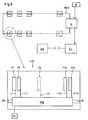
- the openings 174 should be arranged in the spinning machine in such a way that the sensor (not shown) held by a bracket 178 opposite a ring 180 is centered (positioned), as can be seen in particular from FIG. 4, wherein It should be clarified that for simplification in FIG. 4 only the inner edge 182 of the Ring 180 and the outer edge of the ring holder 184 have been shown specifically.
- the breakthroughs 174 must be in the body 152 after continuous casting are pierced with adjacent openings 174 a predetermined Have a distance which is the division of the Spinning positions (ring axes) corresponds. It is then when assembling the profile body required the exact positioning of the whole body 152 in the longitudinal direction of the To ensure ring frame without paying attention to the individual brackets 178 have to.
- the fastener can e.g. Clamping screws comprise, which hold the body 152 on the ring frame 150 without it to Tighten against shifting longitudinally of the groove 164 (i.e. in To prevent longitudinal direction of the ring frame 150). Only when the body 152 in the is in the correct position in the longitudinal direction, the clamping screws screwed tight.
- the elements 186 in FIG. 4 schematically represent fastening elements, with which the ring holder is fastened to the ring frame 150, while the element 188 represents a so-called rotor cleaner, as has been shown, for example, in DE-A-197 53 767.
- the rotor itself is indicated in FIG. 4 with the reference number 190.
- the ring 180 shown in Fig. 3 is a so-called Inclined flange ring "(for example according to EP-B-528 056).
- the invention can be used with other ring types.
- the bracket 178 is designed to hold a magnetic sensor that is on the revolutions of the rotor 190 on the ring 180 during spinning.
- a magnetic sensor that is on the revolutions of the rotor 190 on the ring 180 during spinning.
- the invention is not in one anyway certain sensor type, although it is obviously advantageous to use one contactless sensor to choose. For this execution it is important to notice that the sensor has to move with the ring frame, which is here this ensures that the sensor is attached to the ring frame.
- FIG. 3A A corresponding solution is shown in FIG. 3A (in a larger one Scale) is shown schematically.
- the inside of wall 172 is covered with several (here, three) provided in the longitudinal direction extending grooves 200. These grooves can in continuous casting at precisely predetermined locations compared to the Contact surface 158 are formed.
- a clamp 202 of the Fastening means for the bracket 178 is provided with ribs 204 which in one or other of the grooves 202 may engage to form a snap connection.
- the distance of the sensor, not shown, from the central axis of the ring 180 depends therefore depends on which groove 200 is selected. With a selection (as in Fig. 3A shown), the bracket mount can be in contact with one end of the Breakthrough 174 come in at another selection with the other end of the Breakthrough 174 and in the third selection, the attachment can freely between the Ends of the breakthrough.
- the clamp piece 202 should be the required one Have elasticity to ensure a firm connection between the bracket 174 and the Body 152 to ensure without the releasability of this connection affect.
- Sections Long spinning machines are usually divided into individual sections ( Sections ") so that assembly can take place at least in part in the manufacturing plant and, on the other hand, assemblies can be assembled in the spinning mill without too much effort during final assembly.
- Such a concept is known, for example, from German Patent DE 882 967 Spinning machine is essentially divided into longitudinal parts, which are arranged in alignment, the longitudinal parts being connected to one another with cross parts or shields be self-supporting ", ie it should be able to be assembled without assistance from adjacent sections.
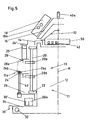
- the general principle can be seen in FIG. 5. Accordingly, a section of a ring spinning machine comprises between two plates 12 (only one plate 12 is visible in FIG.
- a doffing support 34 with a doffing support 32 in the lower part a doffing support 34 with a doffing support 32, a protective rail 30 being attached to the outside of the doffing support, a cable duct 30a and a spindle frame part 26, which are attached to the side of the shield 12, at the lower part of the shield.
- a number are seated on the spindle frame part 26 Spindles 40 (this number is discussed in more detail below). Furthermore are laterally attached to the shield 12 holder 22 for guide rods 20, which are vertical movably guide a ring frame part 24 and a thread guide frame part 28.
- the Longitudinal parts of the ring frame 24, thread guide frame 28 are also provided with cross members 20b, 20a the guide rod 20 connected.
- a long spinning machine can contain a thousand and more spinning stations, each with a spindle 40 and a ring traveler combination 24a, 24b and a drafting station work.
- the described parts together form a more or less complete (double-sided) section of such a long spinning machine 10, this section or section being a predetermined one (from the manufacturer standardized ") number of spindles or spinning stations.
- a suitable number of spinning stations per section is for example eighty-forty, ie four and twenty per side of a double-sided section.
- the invention is in no way limited to this number, that of a manufacturer can be different from another.
- brackets 178 per profile body 152 of the number of rings 180 of the corresponding ring frame section should be the same, this number depends on the manufacturer's assembly concept. But it will also be clear that the Arrangement not based on the equality of the profile body length and the section length of one certain machine is restricted. It would be possible e.g. two or more To use profile bodies per side of a machine section. But it would be absent possible to deliver each profile body in a standardized length, which none certain machine section concept is adapted, then each body if necessary, must be cut to match the application adapt.
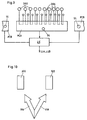
- Fig. 6 therefore shows schematically fifty section units S1 ------ S50, which by means of a BUS are connected to an adapter A, and further details of a single one Unit S25, which serves as an example for the others, because all units S1 to S50 are the same are.
- the unit S25 comprises a computer chip (Printed Circuit Board) PCB as well individual lines L1 to L24 between input / output points on this chip and individual connecting elements V1 to V24.
- the connecting elements V1 to V24 are designed and attached to respective openings 174 (Fig. 3) that when a holder 178 is inserted into its receiving opening 174, the signal insertion or outputs of the sensor carried by this holder automatically (without further notice To do) are connected to the chip PCB via the respective line Lx.
- the chip PCB is also with main signal input or output means HS for connection to the BUS.
- the BUS can e.g. implemented as a so-called Ethernet bus the invention is not limited to this type of bus.
- each computer PCB is connected to an associated signal lamp SL. The The purpose of this lamp is explained in more detail below.
- Adapter A does not have to be provided with its own computer. It serves to connect the BUS to other control units, in particular to the machine control or its energy supply M and a central unit ZE for evaluating the information supplied by the sensors.
- the central unit ZE can in turn be connected to a data acquisition or process control system SW, for example to one from the applicant company under the name SPIDERWEB "system.
- SPIDERWEB system.
- this connection will not be discussed in more detail here, because the invention has nothing to do with it.
- all connections are preferably designed for bilateral communication.
- the chip PCB of each section is in the cover 168 of the section assigned to that section Profile body 152 housed.
- the line Lx (see Fig. 6, not shown in Fig. 3) for a sensor extends from the chip PCB in the direction of the opening 174, whereby the Sensor bracket 178 to be attached to the body 152.
- the line can with a quick connector (not shown), making it easy to connect with a corresponding line connected to the sensor for signal transmission can be connected.
- the main inputs and outputs (HS, Fig. 6) can be at Mount the carrier connected to the inputs and outputs of the neighboring chips become.
- the profile bodies 152 with their covers 168 thus form a cable or Wiring channel, making the electronic parts and their Connection lines are protected.
- the chip PCB uses the output signal from the sensor to determine whether the Runner periodically passes the sensor (thread is wound up) or not (thread is not wound up). In case b), the chip PCB also needs the number Can determine rotor revolutions per given unit of time. The chip is preferably also able to detect faulty sensors.
- the signal lamp SL (FIG. 6) assigned to this section should be illuminated in order to indicate to the operator in which section the error has occurred. It would be advantageous to identify the error messages with a spindle identification (eg number) and possibly with a Time stamp ". However, based on messages per section (without time stamp), the central unit ZE or the data acquisition SW is able to evaluate and display the operating behavior of the machine so that the operator can intervene. If no time stamp can be sent , an event is preferred immediately "by means of a Telegram "to the head office, where the time of the message can be recorded.
- a spindle identification eg number
- Time stamp e.g number
- the central unit ZE or the data acquisition SW is able to evaluate and display the operating behavior of the machine so that the operator can intervene. If no time stamp can be sent , an event is preferred immediately "by means of a Telegram "to the head office, where the time of the message can be recorded.
- the chips PCB In order to make this possible and also to avoid misinterpretations during standstill, when starting up and when spinning off, the chips PCB must be informed from the central office ZE about the current state of the machine, or they have to receive commands that contain certain evaluations in the chips trigger and / or suppress.
- the holder 178 has an attachment 300 which receives the sensor device 302.
- the sensor device 302 is connected to the PCB via a line 304.
- the device 302 includes, for example, a means for generating a magnetic field and a Hall effect sensor (not specifically indicated), which are those caused by the rotor Disturbances "in the field.
- the holder 178 also carries a light source (for example a light diode 306), which is likewise connected to the PCB by means of a line 308. The function of this light source 306 is explained below.
- the cover 168 also serves certain electronic parts (in particular one Computer board "PCB). This is possible in principle, but it is not the preferred solution.
- the electronic parts PCB are preferably attached independently of the cover 168 and behind it in the channel, with the aid of suitable means Removable fasteners are easy to attach and remove, so these parts are easily accessible for maintenance when the cover is removed.
- the PCB is connected to an evaluation center, as explained in the previous description and is not repeated here.
- the PCB can directly Switch on power supply for light source 306 so that immediately and at the affected point this error is displayed.
- the mistake is also made to the Head office reported so that it also appears there for display.
- the operator will be informed as soon as possible and able to forward to prevent faulty heads. In this case, the rapid intervention is of greater importance Significance because the follow-up costs in further processing are considerable.
- a signal lamp assigned to the machine section can be illuminated to indicate to the operator in which section of the long Spinning machine the error has occurred.
- the light source 306 need not necessarily be provided in the holder 178 , it could also be attached to the machine separately, but preferably in the immediate vicinity of the affected spindle.
- An alternative solution would be generate an advertisement only at the head office or at a section sub-head office. The Combination with the sensor when connected directly to the PCB will Preferred.
- FIG. 8 schematically shows three ring spinning machines 310, 312 and 314 next to one another in a plan, the machine longitudinal axes Ax being arranged parallel to one another.
- Each machine has a long side LA and a long side LB arranged in mirror image to the long side LA.
- Each machine has an end head K at one end and a foot unit F at the other end.
- the end heads K are on a main aisle (aisle 1) and the foot units F are also on a main aisle (aisle 2).
- the main aisles are connected to one another by service aisles BG1 and BG2, which extend between adjacent machines.
- the middle parts of the machine viewed in the longitudinal direction, have been omitted because the respective end parts are sufficient to explain the operator guidance concept.
- each long side LA or LB has spinning section sections S1, S2, S3 ... etc., with only the sections S1, S2, S24 and S25 on the long side LB in FIG of machine 314 are specifically shown.
- Each section comprises brackets according to FIG. 7, each with an indicator lamp 306.
- each end head and each foot unit is provided with a lamp LLA assigned to the long side LA and a lamp LLB assigned to the long side LB.
- a spinning station of a certain machine side for example the LB side of machine 314.
- a person in main aisle 1 or 2 is therefore led to foot unit F of machine 314. If the lamp LLB on the foot unit F in the main aisle 1 is not clearly perceptible, the lamp LLB on the end head K of the machine 314 can also be illuminated. If it is assumed that the defective spinning station is in the vicinity of the foot unit F and only the lamp LLB of this unit lights up, it is possible that the operator can now perceive the illuminated indicator lamp 306 from the foot unit F and start the affected spinning station directly .
- FIG. 9 A driver concept for this operator guidance is shown schematically in FIG. 9, where a Section computer PCB24 (see FIG. 6) and the end parts of both neighboring computers PCB23 and PCB25 are shown schematically, each with the assigned signal lamp SL.
- the signals from the sensors 302 are evaluated in the corresponding computer PCB and the lighting of the indicator lamp 306 one defective spinning station and the signal lamp SL of the corresponding section is immediately initiated by the computer PCB.
- FIG. 10 shows that it is not absolutely necessary to have one indicator lamp per To provide spinning station. Instead, you could use a common lamp per Provide pair of spinning stations, the light through one or the other opening of a Pair of openings should shine, the one (e.g. arrow-shaped) opening 316 on the one Spinning station 320 and the other opening 318 points to the other spinning station 322. It would also be possible to provide only one lamp per section, but the light by means of a suitable light guide to a suitable display near the affected spinning station if a defect is found.
- FIG. 11 shows a further development of the embodiment according to FIG. 3, wherein wherever possible the same reference numbers have been used for the same parts, especially for the ring frame 150 (including its front side 156), ring 180, rotor 190 and ring holder 184.
- the profile body 152 of FIG. 3 is through in FIG. 11 a base part 330 has been replaced.
- the base part 330 has a bottom 332 through suitable means (not shown) is secured to the front of the ring frame 156.
- the Base part carries two projecting walls 334, 336, each wall with an inner bead 338 is provided at the end remote from the ring frame.
- the walls In principle, 334, 336 could be formed in one piece with the ring frame 150 become.
- the beads 338 are suitable for the formation of a form-fitting, releasable Connection with connecting elements 340, 342 of a holder 344 for the Rotor sensor 346 and / or the spin position indicator 348.
- the walls 334,336 can be relatively rigid with respect to elements 340, 342, or both Walls 334,336 as well as elements 340,342 can be elastically deformable, to enable a detachable snap connection.
- the bracket 344 can Plastic, preferably in one piece. It also includes Connecting elements 340, 342 a hollow projection 350, which in FIG Part is cut away to show the sensor 346 held therein, as well as one Bezel 352 for display 348, which may be in the form of a signal lamp.
- the connecting elements 340, 342 also serve as fastening elements for one Signal evaluation unit SA, which is connected by means of conductor 354, 356 to display 348 and is connected to sensor 346.
- SA Signal evaluation unit
- the bracket 344 too forms a partial cover for the channel within the base 330, the position the holder 344 is not (pre) determined in the machine longitudinal direction, but by slide the bracket in the longitudinal direction of the base 330 can be adjusted.
- This variant therefore requires a clean assembly of the bracket 344 on Ring frame to ensure that the sensors 346 each have a ring 180 or rotor Face 190. If the touch field of each sensor was chosen correctly the output signal of the respective sensor is not due to smaller shifts in the machine longitudinal direction sensitive.
- the bracket 344 with those carried by it Sharing now forms a signal generation, evaluation, and display module that Signals to the section computer (not shown in Fig. 11).
- FIG. 12 shows a module 356, which comprises two projections 350.
- the two projections 350 each receive a sensor, so that the sensors are each assigned to a spindle (not shown) after installation in the machine.
- This variant also includes two mounts 352 for one signal lamp 348 each, the signal lamps 348 also being assigned to a spindle.
- the module 356 can be provided with a common signal evaluation unit (not shown) for the two sensors.
- the connecting elements 340, 342 do not necessarily extend over the entire length of the module 356 (viewed in the machine longitudinal direction).
- Both element 340 and element 342 can be made from a plurality of elastically deformable Claws "are formed, whereby at least two claws should be provided at the top (element 340) and two claws at the bottom (element 342).
- the distance Ab between the axes of the projections 350 can correspond to the spindle pitch or can only be adapted to the spindle pitch. It is known to deliver ring spinning machines of generally the same type either with a spindle pitch of 75 mm. or a spindle pitch of 70 mm. If the sensor type is selected correctly (with a wide touch field), both can be achieved, for example, with a distance Ab of 72.5 mm Machine types are covered by a common module 356. However, it is then at most necessary to use spacers between adjacent modules in order to ensure complete coverage of the channel in the base 344 with a spindle pitch of 75 mm.
- FIG. 13 shows (on a different scale) a module 360 with four protrusions 350.
- This quad module can be used in combination with the double module according to FIG. 12, for example in such a way that for one Section "with 24 spindles per machine longitudinal side, ten double modules 356 and a four module 360 can be used on both sides.
- the four module not only includes the signal evaluations (not shown) for the own sensors, but also the section computer (not shown) and the section display (signal lamp Since the details of the quad module 360 result from the description of the double module 356, a more detailed description or illustration of the quad module is omitted.
Landscapes
- Engineering & Computer Science (AREA)
- Mechanical Engineering (AREA)
- Textile Engineering (AREA)
- Spinning Or Twisting Of Yarns (AREA)
Abstract

Description

- US-B-2,930,179; US-B-2,930,180 und US-B-3,102,378
- FR-A-1,518,050
- DE-A-2,505,399
- EP-A-329 618
- CH-B-556 923
- JP-A-GM 6-83777
- DE-A-40 35 385.
- Fig. 1
- einen Querschnitt durch einen Ringrahmen mit den umgebenden Teilen einer Ringspinnmaschine gemäss DE-A-195 42 802,
- Fig. 2
- eine perspektivische Darstellung eines Teils des Ringrahmens,
- Fig. 3
- einen Querschnitt durch einen Ringrahmen einer Ringspinnmaschine mit einem Träger gemäss der vorhergehenden Erfindung,
- Fig. 3A
- ein Detail aus Fig. 3,
- Fig. 4
- eine vereinfachte Ansicht in Richtung des Pfeils P in Fig. 3,
- Fig. 5
- eine schematische Darstellung einer Seite einer Ringspinnmaschine im Querschnitt,
- Fig. 6
- schematisch ein Sensoriksystem, das gemäss dem Konzept nach der vorliegenden Erfindung zusammengestellt werden kann.
- Fig. 7
- eine schematische Darstellung einer Vorrichtung zur Verwendung mit einem Träger nach den Figuren 3 und 4,
- Fig. 8
- einen schematischen Plan einer Gruppe benachbarter Ringspinnmaschinen zur Erklärung eines Bedienerführungskonzeptes,
- Fig. 9
- eine schematische Darstellung der Anzeigemittel einer Sektion einer Maschine gemäss der vorliegenden Erfindung,
- Fig. 10
- eine schematische Darstellung einer alternativen Spinnstellenanzeige nach der Erfindung,
- Fig. 11
- einen schematischen Querschnitt durch eine Anordnung, die anstelle der Anordnung nach der Figur 3 verwendet werden kann,
- Fig. 12
- schematisch eine erste Variante eines Moduls gemäss der vorliegenden Erfindung zur Verwendung in einer Anordnung gemäss Fig. 11, und
- Fig. 13
- eine zweite Variante eines solchen Moduls.
- einerseits ein Ringrahmen 150 (Fig. 3) gemäss dem Konzept der Sektionsmontage aus einer Vielzahl von länglichen Teilstücken zusammengestellt wird, wobei die Länge des Teilstückes der Länge einer Sektion im wesentlichen gleich ist, und
- andererseits die Länge des Profilkörpers 152 (Fig. 3) vorzugsweise der Länge der Sektion angepasst wird, sodass jeder Profilkörper 152 einem jeweiligen Ringrahmenteilstück zugeordnet werden kann.
- die an der Spinnmaschine anzubringende Sensorik nicht direkt an die Verdrahtung der Maschine angeknüpft werden kann bzw. dass die Zentraleinheit ZE nicht direkt in die Maschinensteuerung integriert werden kann, und
- die Sensorik muss nicht mit einer Luntenstopp-Funktion (z.B. gemäss DE-A-35 26 305) verbunden werden. Die Erfindung ist aber nicht zur Verwendung innerhalb dieser Rahmenbedingungen eingeschränkt, d.h. sie kann z.B als Alternative im Rahmen eines Systems gemäss EP-B-389 849 realisiert werden.
- erhält bei der Initialisierung von der Zentrale ZE die Parameter
- Minimaldrehzahl (Faden läuft)
- der Zeitintervall, der für die Ermittlung von sogenannten
- berechnet aus den Signalen für die korrekt laufenden Spindeln eine mittlere Sektionsdrehzahl
- ermittelt einen Sammelzustand über ihre zugeordneten Spindeln für
- Fadenbruch (brüche) vorhanden
- Schleicherspindel(n) vorhanden
- Sensoren defekt.
- erhält periodisch von der Zentrale ZE eine Drehzahl für die Ermittlung der Schleicherspindeln. Spindeln, die länger als das definierte Schleicher-Zeitintervall langsamer als die vorgegebene Drehzahl laufen, werden als Schleicherspindel erfasst.
- ermittelt im Betrieb zyklisch den Spinnstellenzustand und steuert bei Bedarf die Signallampe SL beim Aussenden eines Ereignistelegramms an die Zentrale ZE.
- ermittelt während der Anlauf- und/oder der Doffphase die Anzahl Fadenbrüche. In dieser Phase müssen die Fadenbrücheinformationen in der Sektion gespeichert werden und beim Anfragen von der Zentrale aus (nach der Beendigung der speziellen Phase) als Sondermeldung gesendet werden. Während einer solchen Phase wird die Spindeldrehzahl normalerweise nicht ermittelt, da sie sich stetig ändert. Der Beginn bzw. das Ende einer solchen Phase wird von der Zentrale gemeldet.
- leitet die Signale von den Sektionen weiter
- leitet ein Signal weiter, das angibt, ob die Maschine läuft oder nicht
- gibt ein Doffsignal weiter.
- fasst Spindeldaten zusammen (beispielsweise pro Schicht)
- ermittelt periodisch aus den Sektionsdrehzahlen die Grenzdrehzahl für die Ermittlung der Schleicherspindeln und leitet diese an die Sektionen weiter.
Claims (14)
- Einzelspindelsensor für eine Ringspinnmaschiner zum Abgeben eines Signals, das sowohl zum Anzeigen eines Fadenbruches wie auch zum Anzeigen einesSchleichzustandes" der dem Sensor zugeordneten Spindel ausgewertet werden kann, und eine Auswertung, die das Signal sowohl nach Vorhandensein eines Fadenbruches wie auch nach einem Schleichzustand auswertet, wobei die Auswertung mit einem Anzeigemittel zusammenarbeitet, welches das Vorhandensein eines Schleichzustandes anzeigt, dadurch gekennzeichnet, dass das Anzeigemittel in der Nähe der Spindel vorgesehen ist.

- Sensor nach Anspruch 1, dadurch gekennzeichnet, dass für den Sensor und das Anzeigemittel eine gemeinsame Halterung vorgesehen ist.
- Sensor nach Anspruch 1 oder 2, dadurch gekennzeichnet, dass das Anzeigemittel eine Lampe, beispielsweise eine Lichtdiode, umfasst.
- Sensor nach einem der vorangehenden Ansprüche, dadurch gekennzeichnet, dass der Sensor ein magnetisches Feld erzeugt.
- Sensor nach einem der vorangehenden Ansprüche, dadurch gekennzeichnet, dass der Sensor zum Ansprechen auf die Bewegungen des Läufers geeignet ist.
- Ringspinnmaschine dadurch gekennzeichnet, dass jeder Spinnstelle eine jeweilige Anzeige für den Zustand
- Maschine nach Anspruch 6, dadurch gekennzeichnet, dass die Zuordnung derart gewählt ist, dass eine Bedienungsperson, die an dieser Anzeige steht, auch in der Nähe der betroffenen Spinnstelle stehen muss.
- Maschine nach Anspruch 6 oder 7 dadurch gekennzeichnet, dass die Anzeige unzweideutig angibt, welche Spinnstelle betroffen ist, wobei die Anzeige vorzugsweise visuell wahrnehmbar ist, beispielsweise in der Form einer Signallampe.
- Maschine nach einem der Ansprüche 6 bis 8, dadurch gekennzeichnet, dass eine Anzeige pro Spinnstelle vorgesehen ist.
- Maschine nach einem der Ansprüche 6 bis 9, dadurch gekennzeichnet, dass die Anzeige derart der Spinnstelle zugeordnet ist, dass sie auch von entfernten Positionen, z.B. vom Maschinenende, wahrnehmbar ist.
- Maschine nach einem der Ansprüche 6 bis 10, dadurch gekennzeichnet, dass die einzelnen Spinnstellen-Anzeigen durch Grossraumanzeigen ergänzt sind, welche die Bedienung von relativ weither an einem Ort führen können, der sich als Ausgangspunkt für den Anlauf an die anzeige einer betroffenen Spinnstelle eignet.
- Maschine nach Anspruch 11 dadurch gekennzeichnet, dass an mindestens einem und vorzugsweise jedem Maschinenende eine Grossraumanzeige pro Maschinenseite vorgesehen ist.
- Maschine nach einem der Ansprüche 6 bis 12, dadurch gekennzeichnet, dass für jede Maschinenseite mehrere, über die Maschinenlänge verteilten Abschnittsanzeigen vorgesehen sind, vorzugsweise eine solche Anzeige pro Wegstrecke, die einer vorgegebenen Anzahl Spinnstellen entspricht.
- Maschine nach einem der Ansprüche 6 bis 13 dadurch gekennzeichnet, dass zur Erkennung von Schleichspindeln einen Einzelspindelsensor pro Spinnstelle vorgesehen ist, wobei der Sensor vorzugsweise zum Abgeben eines Signals geeignet ist, das sowohl zum Anzeigen eines Fadenbruches wie auch zum Anzeigen eines
Applications Claiming Priority (2)
| Application Number | Priority Date | Filing Date | Title |
|---|---|---|---|
| DE19929467 | 1999-06-26 | ||
| DE19929467A DE19929467A1 (de) | 1999-06-26 | 1999-06-26 | Sensorik für Ringspinnmaschine |
Publications (3)
| Publication Number | Publication Date |
|---|---|
| EP1074645A1 true EP1074645A1 (de) | 2001-02-07 |
| EP1074645B1 EP1074645B1 (de) | 2004-01-02 |
| EP1074645B2 EP1074645B2 (de) | 2008-11-05 |
Family
ID=7912753
Family Applications (1)
| Application Number | Title | Priority Date | Filing Date |
|---|---|---|---|
| EP00202201A Expired - Lifetime EP1074645B2 (de) | 1999-06-26 | 2000-06-26 | Sensorik für Ringspinnmaschine |
Country Status (3)
| Country | Link |
|---|---|
| EP (1) | EP1074645B2 (de) |
| AT (1) | ATE257186T1 (de) |
| DE (2) | DE19929467A1 (de) |
Cited By (4)
| Publication number | Priority date | Publication date | Assignee | Title |
|---|---|---|---|---|
| JP2005535794A (ja) * | 2002-08-13 | 2005-11-24 | マシーネンファブリク リーター アクチェンゲゼルシャフト | リング紡糸機のためのセンサ装置 |
| WO2006024362A1 (de) * | 2004-09-02 | 2006-03-09 | Saurer Gmbh & Co. Kg | Ringspinnmaschine |
| CN114074861A (zh) * | 2020-08-20 | 2022-02-22 | 卓郎纺织解决方案两合股份有限公司 | 具有多个相同工位的纺织机 |
| CN115341312A (zh) * | 2021-05-15 | 2022-11-15 | 尚科纺织企业工业及贸易公司 | 在环锭纺纱或加捻机中卷绕和加捻纤维材料的设备和方法 |
Families Citing this family (3)
| Publication number | Priority date | Publication date | Assignee | Title |
|---|---|---|---|---|
| DE102014018628A1 (de) | 2014-12-13 | 2016-06-16 | Saurer Germany Gmbh & Co. Kg | Vielstellentextilmaschine |
| ITUB20154712A1 (it) * | 2015-10-22 | 2017-04-22 | Marzoli Machines Textile Srl | Dispositivo di rilevazione per un fuso di un filatoio |
| DE102017114792A1 (de) | 2017-07-03 | 2019-01-03 | Saurer Spinning Solutions Gmbh & Co. Kg | Ringspinnmaschine mit einer Vielzahl von Spinnstellen |
Citations (4)
| Publication number | Priority date | Publication date | Assignee | Title |
|---|---|---|---|---|
| US4280321A (en) * | 1978-04-24 | 1981-07-28 | F.Lli Marzoli & C. S.P.A. | Safety spindle-stopping device for a spinning frame |
| US4635321A (en) * | 1984-02-21 | 1987-01-13 | Zinser Textilmaschinen Gmbh | Spinning machines and the like with signal or indicator devices |
| DE4228300A1 (de) * | 1992-08-26 | 1994-03-03 | Rieter Ag Maschf | Verfahren und Vorrichtung zur Überwachung von Spinnstellen |
| DE4422523A1 (de) * | 1994-06-28 | 1996-01-04 | Schlafhorst & Co W | Codierung von mehreren gleichgearteten Arbeitsstellen an einer Textilmaschine |
Family Cites Families (8)
| Publication number | Priority date | Publication date | Assignee | Title |
|---|---|---|---|---|
| BE676645A (de) * | 1966-02-17 | 1966-07-18 | ||
| CH540848A (de) † | 1972-01-24 | 1973-08-31 | Zellweger Uster Ag | Verfahren und Vorrichtung zur Beurteilung der Laufeigenschaften von mittels Spindeln arbeitenden Textilmaschinen |
| DE2450207A1 (de) * | 1974-10-23 | 1976-04-29 | Palitex Project Co Gmbh | Verfahren zur erzeugung eines steuersignals beim auftreten eines fadenbruchs an textilmaschinen, insbesondere doppeldrahtzwirnmaschinen, und fadenwaechter zur durchfuehrung des verfahrens |
| DE2946031A1 (de) † | 1979-11-14 | 1981-05-21 | Zinser Textilmaschinen Gmbh, 7333 Ebersbach | Vorrichtung zum abschalten eines elektromotorischen einzelspindelantriebes bei betriebsstoerung an einer textilmaschine |
| CH674377A5 (de) * | 1986-02-11 | 1990-05-31 | Forschungsanwendungs Gmbh | |
| DE4011944A1 (de) * | 1990-04-12 | 1991-10-17 | Zinser Textilmaschinen Gmbh | Vorrichtung zur ueberwachung der drehzahl von ringlaeufern an arbeitsstellen von spinnereimaschinen |
| JPH0816287B2 (ja) † | 1991-09-20 | 1996-02-21 | 日本セレン株式会社 | 精紡機等の糸切れ検出装置 |
| DE4211684A1 (de) * | 1992-04-07 | 1993-10-14 | Rieter Ag Maschf | Verfahren und Vorrichtung zur Drehzahlregelung von Spinnmaschinen |
-
1999
- 1999-06-26 DE DE19929467A patent/DE19929467A1/de not_active Withdrawn
-
2000
- 2000-06-26 DE DE50004912T patent/DE50004912D1/de not_active Expired - Lifetime
- 2000-06-26 AT AT00202201T patent/ATE257186T1/de not_active IP Right Cessation
- 2000-06-26 EP EP00202201A patent/EP1074645B2/de not_active Expired - Lifetime
Patent Citations (4)
| Publication number | Priority date | Publication date | Assignee | Title |
|---|---|---|---|---|
| US4280321A (en) * | 1978-04-24 | 1981-07-28 | F.Lli Marzoli & C. S.P.A. | Safety spindle-stopping device for a spinning frame |
| US4635321A (en) * | 1984-02-21 | 1987-01-13 | Zinser Textilmaschinen Gmbh | Spinning machines and the like with signal or indicator devices |
| DE4228300A1 (de) * | 1992-08-26 | 1994-03-03 | Rieter Ag Maschf | Verfahren und Vorrichtung zur Überwachung von Spinnstellen |
| DE4422523A1 (de) * | 1994-06-28 | 1996-01-04 | Schlafhorst & Co W | Codierung von mehreren gleichgearteten Arbeitsstellen an einer Textilmaschine |
Cited By (7)
| Publication number | Priority date | Publication date | Assignee | Title |
|---|---|---|---|---|
| JP2005535794A (ja) * | 2002-08-13 | 2005-11-24 | マシーネンファブリク リーター アクチェンゲゼルシャフト | リング紡糸機のためのセンサ装置 |
| CN1688756B (zh) * | 2002-08-13 | 2010-05-12 | 里特机械公司 | 环锭纺纱机的传感器系统 |
| WO2006024362A1 (de) * | 2004-09-02 | 2006-03-09 | Saurer Gmbh & Co. Kg | Ringspinnmaschine |
| CN114074861A (zh) * | 2020-08-20 | 2022-02-22 | 卓郎纺织解决方案两合股份有限公司 | 具有多个相同工位的纺织机 |
| CN114074861B (zh) * | 2020-08-20 | 2023-08-25 | 卓郎纺织解决方案两合股份有限公司 | 具有多个相同工位的纺织机 |
| CN115341312A (zh) * | 2021-05-15 | 2022-11-15 | 尚科纺织企业工业及贸易公司 | 在环锭纺纱或加捻机中卷绕和加捻纤维材料的设备和方法 |
| CN115341312B (zh) * | 2021-05-15 | 2024-02-09 | 尚科纺织企业工业及贸易公司 | 在环锭纺纱或加捻机中卷绕和加捻纤维材料的设备和方法 |
Also Published As
| Publication number | Publication date |
|---|---|
| ATE257186T1 (de) | 2004-01-15 |
| DE19929467A1 (de) | 2000-12-28 |
| EP1074645B2 (de) | 2008-11-05 |
| DE50004912D1 (de) | 2004-02-05 |
| EP1074645B1 (de) | 2004-01-02 |
Similar Documents
| Publication | Publication Date | Title |
|---|---|---|
| EP1065303B1 (de) | Textilmaschine mit einer Vielzahl gleichartiger Arbeitsstellen | |
| EP3031761B1 (de) | Vielstellentextilmaschine | |
| DE1907990C2 (de) | Verfahren und Vorrichtung zum Überwachen von Fadenstellen einer Textilmaschine auf Fadenbruch | |
| EP0389849A2 (de) | Steuersystem für eine Textilmaschine | |
| EP1074645B1 (de) | Sensorik für Ringspinnmaschine | |
| DE19907684B4 (de) | Textilmaschine mit Prozessoren an den Arbeitsstellen | |
| EP2957663B1 (de) | Verfahren zum betreiben einer offenend-spinnmaschine | |
| DE102008000610B4 (de) | Sensor für eine Textilmaschine | |
| EP1052314B1 (de) | Sensorik für Ringspinnmaschine | |
| DE3210333A1 (de) | Einrichtung zur elektrischen kettfadenueberwachung bei webmaschinen | |
| DE102017006137A1 (de) | Schmelzspinnvorrichtung | |
| DE19547068A1 (de) | Serviceeinrichtung an einer Spinnmaschine | |
| DE102012103531B4 (de) | Textilmaschine mit einer Aufnahmevorrichtung für eine zweite Schleppkettenführung | |
| DE102004058920B4 (de) | Rundstrickmaschine und Elektromotor | |
| WO1985004908A1 (fr) | Metier a filer | |
| EP0905294B1 (de) | Bestückungsüberwachung an einer Vorspinnmaschine | |
| EP4169859A1 (de) | Kreuzspulenherstellende textilmaschine mit einer vielzahl gleichartiger, nebeneinander angeordneter arbeitsstellen und einer entlang der arbeitsstellen verfahrbaren bedieneinrichtung sowie verfahren zum betreiben einer solchen kreuzspulenherstellenden textilmaschine | |
| EP3673103A1 (de) | Verfahren zum betreiben einer ringspinnmaschine und ringspinnmaschine | |
| DE3902820A1 (de) | Verfahren und vorrichtung zum uebermitteln von informationen ueber betriebszustaende an einer ringspinnmaschine | |
| DE4422523A1 (de) | Codierung von mehreren gleichgearteten Arbeitsstellen an einer Textilmaschine | |
| CH714081A1 (de) | Verfahren zum Betreiben einer Ringspinnmaschine und Ringspinnmaschine. | |
| DE2460375A1 (de) | Offenend-spinnmaschinenanlage | |
| DE102012104667A1 (de) | Vorrichtung zum gemeinsamen Wechseln einer Mehrzahl von Hülsen an einer Textilmaschine mit einem Greiferbalken | |
| LU504361B1 (de) | Sektionsbaugruppe für Kablier- und/oder Zwirnmaschine | |
| DE10020694A1 (de) | Spinnmaschine mit einer Vielzahl von Spinnstellen |
Legal Events
| Date | Code | Title | Description |
|---|---|---|---|
| PUAI | Public reference made under article 153(3) epc to a published international application that has entered the european phase |
Free format text: ORIGINAL CODE: 0009012 |
|
| AK | Designated contracting states |
Kind code of ref document: A1 Designated state(s): AT BE CH CY DE DK ES FI FR GB GR IE IT LI LU MC NL PT SE |
|
| AX | Request for extension of the european patent |
Free format text: AL;LT;LV;MK;RO;SI |
|
| 17P | Request for examination filed |
Effective date: 20010622 |
|
| AKX | Designation fees paid |
Free format text: AT BE CH CY DE DK ES FI FR GB GR IE IT LI LU MC NL PT SE |
|
| 17Q | First examination report despatched |
Effective date: 20030115 |
|
| GRAP | Despatch of communication of intention to grant a patent |
Free format text: ORIGINAL CODE: EPIDOSNIGR1 |
|
| GRAS | Grant fee paid |
Free format text: ORIGINAL CODE: EPIDOSNIGR3 |
|
| GRAA | (expected) grant |
Free format text: ORIGINAL CODE: 0009210 |
|
| AK | Designated contracting states |
Kind code of ref document: B1 Designated state(s): AT BE CH CY DE DK ES FI FR GB GR IE IT LI LU MC NL PT SE |
|
| PG25 | Lapsed in a contracting state [announced via postgrant information from national office to epo] |
Ref country code: NL Free format text: LAPSE BECAUSE OF FAILURE TO SUBMIT A TRANSLATION OF THE DESCRIPTION OR TO PAY THE FEE WITHIN THE PRESCRIBED TIME-LIMIT Effective date: 20040102 Ref country code: GB Free format text: LAPSE BECAUSE OF FAILURE TO SUBMIT A TRANSLATION OF THE DESCRIPTION OR TO PAY THE FEE WITHIN THE PRESCRIBED TIME-LIMIT Effective date: 20040102 Ref country code: FI Free format text: LAPSE BECAUSE OF FAILURE TO SUBMIT A TRANSLATION OF THE DESCRIPTION OR TO PAY THE FEE WITHIN THE PRESCRIBED TIME-LIMIT Effective date: 20040102 Ref country code: CY Free format text: LAPSE BECAUSE OF FAILURE TO SUBMIT A TRANSLATION OF THE DESCRIPTION OR TO PAY THE FEE WITHIN THE PRESCRIBED TIME-LIMIT Effective date: 20040102 Ref country code: FR Free format text: LAPSE BECAUSE OF FAILURE TO SUBMIT A TRANSLATION OF THE DESCRIPTION OR TO PAY THE FEE WITHIN THE PRESCRIBED TIME-LIMIT Effective date: 20040102 Ref country code: IE Free format text: LAPSE BECAUSE OF FAILURE TO SUBMIT A TRANSLATION OF THE DESCRIPTION OR TO PAY THE FEE WITHIN THE PRESCRIBED TIME-LIMIT Effective date: 20040102 |
|
| REG | Reference to a national code |
Ref country code: GB Ref legal event code: FG4D Free format text: NOT ENGLISH |
|
| REG | Reference to a national code |
Ref country code: CH Ref legal event code: EP |
|
| REG | Reference to a national code |
Ref country code: IE Ref legal event code: FG4D Free format text: GERMAN |
|
| REF | Corresponds to: |
Ref document number: 50004912 Country of ref document: DE Date of ref document: 20040205 Kind code of ref document: P |
|
| PG25 | Lapsed in a contracting state [announced via postgrant information from national office to epo] |
Ref country code: DK Free format text: LAPSE BECAUSE OF FAILURE TO SUBMIT A TRANSLATION OF THE DESCRIPTION OR TO PAY THE FEE WITHIN THE PRESCRIBED TIME-LIMIT Effective date: 20040402 Ref country code: GR Free format text: LAPSE BECAUSE OF FAILURE TO SUBMIT A TRANSLATION OF THE DESCRIPTION OR TO PAY THE FEE WITHIN THE PRESCRIBED TIME-LIMIT Effective date: 20040402 Ref country code: SE Free format text: LAPSE BECAUSE OF FAILURE TO SUBMIT A TRANSLATION OF THE DESCRIPTION OR TO PAY THE FEE WITHIN THE PRESCRIBED TIME-LIMIT Effective date: 20040402 |
|
| PG25 | Lapsed in a contracting state [announced via postgrant information from national office to epo] |
Ref country code: ES Free format text: LAPSE BECAUSE OF FAILURE TO SUBMIT A TRANSLATION OF THE DESCRIPTION OR TO PAY THE FEE WITHIN THE PRESCRIBED TIME-LIMIT Effective date: 20040413 |
|
| NLV1 | Nl: lapsed or annulled due to failure to fulfill the requirements of art. 29p and 29m of the patents act | ||
| PG25 | Lapsed in a contracting state [announced via postgrant information from national office to epo] |
Ref country code: LU Free format text: LAPSE BECAUSE OF NON-PAYMENT OF DUE FEES Effective date: 20040626 Ref country code: AT Free format text: LAPSE BECAUSE OF NON-PAYMENT OF DUE FEES Effective date: 20040626 |
|
| GBV | Gb: ep patent (uk) treated as always having been void in accordance with gb section 77(7)/1977 [no translation filed] |
Effective date: 20040102 |
|
| PG25 | Lapsed in a contracting state [announced via postgrant information from national office to epo] |
Ref country code: MC Free format text: LAPSE BECAUSE OF NON-PAYMENT OF DUE FEES Effective date: 20040630 |
|
| REG | Reference to a national code |
Ref country code: IE Ref legal event code: FD4D |
|
| PLBQ | Unpublished change to opponent data |
Free format text: ORIGINAL CODE: EPIDOS OPPO |
|
| PLBI | Opposition filed |
Free format text: ORIGINAL CODE: 0009260 |
|
| PLAX | Notice of opposition and request to file observation + time limit sent |
Free format text: ORIGINAL CODE: EPIDOSNOBS2 |
|
| 26 | Opposition filed |
Opponent name: SAURER GMBH & CO. KG Effective date: 20041001 |
|
| EN | Fr: translation not filed | ||
| PLBB | Reply of patent proprietor to notice(s) of opposition received |
Free format text: ORIGINAL CODE: EPIDOSNOBS3 |
|
| PG25 | Lapsed in a contracting state [announced via postgrant information from national office to epo] |
Ref country code: PT Free format text: LAPSE BECAUSE OF NON-PAYMENT OF DUE FEES Effective date: 20040602 |
|
| APBP | Date of receipt of notice of appeal recorded |
Free format text: ORIGINAL CODE: EPIDOSNNOA2O |
|
| APAH | Appeal reference modified |
Free format text: ORIGINAL CODE: EPIDOSCREFNO |
|
| PLAB | Opposition data, opponent's data or that of the opponent's representative modified |
Free format text: ORIGINAL CODE: 0009299OPPO |
|
| R26 | Opposition filed (corrected) |
Opponent name: OERLIKON TEXTILE GMBH & CO. KG Effective date: 20041001 |
|
| APBU | Appeal procedure closed |
Free format text: ORIGINAL CODE: EPIDOSNNOA9O |
|
| PLAB | Opposition data, opponent's data or that of the opponent's representative modified |
Free format text: ORIGINAL CODE: 0009299OPPO |
|
| PGFP | Annual fee paid to national office [announced via postgrant information from national office to epo] |
Ref country code: CH Payment date: 20080613 Year of fee payment: 9 |
|
| PUAH | Patent maintained in amended form |
Free format text: ORIGINAL CODE: 0009272 |
|
| STAA | Information on the status of an ep patent application or granted ep patent |
Free format text: STATUS: PATENT MAINTAINED AS AMENDED |
|
| 27A | Patent maintained in amended form |
Effective date: 20081105 |
|
| AK | Designated contracting states |
Kind code of ref document: B2 Designated state(s): AT BE CH CY DE DK ES FI FR GB GR IE IT LI LU MC NL PT SE |
|
| REG | Reference to a national code |
Ref country code: CH Ref legal event code: AEN Free format text: AUFRECHTERHALTUNG DES PATENTES IN GEAENDERTER FORM |
|
| REG | Reference to a national code |
Ref country code: ES Ref legal event code: FD2A Effective date: 20040628 |
|
| PGFP | Annual fee paid to national office [announced via postgrant information from national office to epo] |
Ref country code: BE Payment date: 20080728 Year of fee payment: 9 |
|
| BERE | Be: lapsed |
Owner name: MASCHINENFABRIK *RIETER A.G. Effective date: 20090630 |
|
| REG | Reference to a national code |
Ref country code: CH Ref legal event code: PL |
|
| PG25 | Lapsed in a contracting state [announced via postgrant information from national office to epo] |
Ref country code: LI Free format text: LAPSE BECAUSE OF NON-PAYMENT OF DUE FEES Effective date: 20090630 Ref country code: CH Free format text: LAPSE BECAUSE OF NON-PAYMENT OF DUE FEES Effective date: 20090630 |
|
| PG25 | Lapsed in a contracting state [announced via postgrant information from national office to epo] |
Ref country code: BE Free format text: LAPSE BECAUSE OF NON-PAYMENT OF DUE FEES Effective date: 20090630 |
|
| PGFP | Annual fee paid to national office [announced via postgrant information from national office to epo] |
Ref country code: DE Payment date: 20160621 Year of fee payment: 17 |
|
| PGFP | Annual fee paid to national office [announced via postgrant information from national office to epo] |
Ref country code: IT Payment date: 20160628 Year of fee payment: 17 |
|
| REG | Reference to a national code |
Ref country code: DE Ref legal event code: R119 Ref document number: 50004912 Country of ref document: DE |
|
| PG25 | Lapsed in a contracting state [announced via postgrant information from national office to epo] |
Ref country code: DE Free format text: LAPSE BECAUSE OF NON-PAYMENT OF DUE FEES Effective date: 20180103 |
|
| PG25 | Lapsed in a contracting state [announced via postgrant information from national office to epo] |
Ref country code: IT Free format text: LAPSE BECAUSE OF NON-PAYMENT OF DUE FEES Effective date: 20170626 |