EP1073159A2 - Schalteinrichtung mit einem Wechselstromeinlass und einem Wechselstromschalter - Google Patents
Schalteinrichtung mit einem Wechselstromeinlass und einem Wechselstromschalter Download PDFInfo
- Publication number
- EP1073159A2 EP1073159A2 EP00116030A EP00116030A EP1073159A2 EP 1073159 A2 EP1073159 A2 EP 1073159A2 EP 00116030 A EP00116030 A EP 00116030A EP 00116030 A EP00116030 A EP 00116030A EP 1073159 A2 EP1073159 A2 EP 1073159A2
- Authority
- EP
- European Patent Office
- Prior art keywords
- switch
- inlet
- strip
- terminal
- connecting strip
- Prior art date
- Legal status (The legal status is an assumption and is not a legal conclusion. Google has not performed a legal analysis and makes no representation as to the accuracy of the status listed.)
- Granted
Links
Images


Classifications
-
- H—ELECTRICITY
- H01—ELECTRIC ELEMENTS
- H01R—ELECTRICALLY-CONDUCTIVE CONNECTIONS; STRUCTURAL ASSOCIATIONS OF A PLURALITY OF MUTUALLY-INSULATED ELECTRICAL CONNECTING ELEMENTS; COUPLING DEVICES; CURRENT COLLECTORS
- H01R13/00—Details of coupling devices of the kinds covered by groups H01R12/70 or H01R24/00 - H01R33/00
- H01R13/66—Structural association with built-in electrical component
- H01R13/70—Structural association with built-in electrical component with built-in switch
-
- H—ELECTRICITY
- H01—ELECTRIC ELEMENTS
- H01H—ELECTRIC SWITCHES; RELAYS; SELECTORS; EMERGENCY PROTECTIVE DEVICES
- H01H1/00—Contacts
- H01H1/58—Electric connections to or between contacts; Terminals
- H01H1/5866—Electric connections to or between contacts; Terminals characterised by the use of a plug and socket connector
Definitions
- the present invention relates to a switch device having an AC inlet and an AC switch which are accommodated within a common bracket.
- the invention is concerned with a connecting structure for connecting terminals electrically with each other.
- a switch device in which a common bracket formed of an insulating material such as a synthetic resin is provided with receptacle portions, and an AC inlet and an AC switch are fitted in those receptacle portions respectively, and a switch device in which a bracket is allowed to also serve as an insulating base of an AC inlet, and an AC switch is attached thereto.
- connection with the connecting strip is a solid connection made by caulking or soldering, the connection is deficient in flexibility.
- an attachment plug for the supply of an alternating current from an external power supply is inserted and pulled out with respect to the terminal of the AC inlet, an external force is exerted on the terminal, giving rise to the problem that the connection between the terminal and the connecting strip is damaged or an unstable contact results.
- the connecting strip becomes unstable in its held state and there remains a problem to be solved in point of assemblability and reliability of connection.
- a switch device comprising an AC inlet having a connecting pin for AC input and an inlet terminal for connection, an AC switch having a connecting-side terminal and an output-side terminal, a metallic connecting strip for electrically connecting the inlet terminal of the AC inlet and the connecting-side terminal of the AC switch with each other, and a bracket with the AC inlet and AC switch attached thereto, wherein the connecting strip is formed of a flat metallic strip and has a bent portion at an intermediate position of the connection between the inlet terminal and the connecting-side terminal of the AC switch.
- the bent portion of the connecting strip is bent in a generally U shape in the thickness direction of the connecting strip to permit longitudinal expansion and contraction of the connecting strip.
- the bottom of the generally U-shaped bent portion of the connecting strip and the vicinity thereof are formed thin to provide a thin-wall portion.
- the bracket is formed with a holding portion for abutment against the connecting strip to hold the connecting strip.
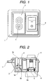
- Fig. 1 is a plan view of a switch device with AC inlet embodying the present invention
- Fig. 2 is a vertical sectional view thereof.
- Fig. 3 is an explanatory diagram showing a connected state of connecting strips
- Fig. 4 is a sectional view showing a mounting portion for an AC switch
- Fig. 5 is a bottom view of a bracket
- Fig. 6 is a vertical sectional view thereof
- Fig. 7 is a plan view of an insulating cover
- Fig. 8 is a vertical sectional view thereof
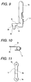
- Fig. 9 is a front view of an inlet terminal
- Fig. 10 is a bottom view thereof
- Fig. 11 is a plan view of a connecting strip
- Fig. 12 is a side view thereof
- Fig. 13 is a plan view of another connecting strip
- Fig. 14 is a side view thereof.
- a bracket 1 is formed in a generally box shape using an insulating material such as a synthetic resin.
- an insulating base 2 of an AC inlet into which is inserted an attachment plug (not shown) for the supply of an alternating current from an external power supply.
- the insulating base 2 is formed in a box shape having a bottom portion 2a whose upper side is open.
- An inlet terminal 3 formed of an electrically conductive metallic material such as brass and having a connecting pin 3a whose tip end is formed in a rod shape, is fixed into each through hole 2b by a suitable method such as press-fitting.
- a connecting piece 3b for connection with a connecting strip to be described later, the connecting piece 3b being extended outside of the bottom portion 2a.
- the connecting piece 3b is positioned so as to be offset outside relative to the position of each through hole 2b which position is the mounting position of the inlet terminal 3.
- the inlet terminal 3 is formed with an arm portion 3c extended in the shape of a strip from a base portion of the inlet terminal and having a flexible distal end. At the distal end of the arm portion 3c is formed a position restricting stepped portion 3d, with the connecting piece 3b as an upright piece being formed on the stepped portion 3d. At one end of the connecting pin 3a the arm portion 3c extends in a direction orthogonal to the axis of the connecting pin. The arm portion 3c is brought into abutment against a lower side of the bottom 2a of the bracket 1 to prevent dislodgment in the projecting direction of the connecting pin 3a.
- a slot 2c contiguously to each through hole 2b.
- An inner width of the slot 2c is set somewhat wide so that the arm portion 3c is movable within the range of the slot 2c.
- the arm portion 3c is restricted its position by the slot 2c, whereby it becomes easy to effect the mounting.
- a free end of the arm portion moves within the range of the slot 2c and therefore any excessive external force is exerted on the connection with the connecting strip to be described later, that is, it is possible to prevent damage of the connection.
- the inlet terminal 3 is integrally formed into a generally L shape by cutting or bending with use of an electrically conductive metallic material.
- the connecting pin 3a is formed in a rod shape of a round section and is press-fitted into a connecting terminal (not shown) of an attachment plug such as a cord for the supply of electric power from an external power supply.
- an AC switch receptacle portion 1a On the right-hand side of the bracket 1 in the figures is formed an AC switch receptacle portion 1a in an opposed relation to the insulating base 2 of the AC inlet, the AC switch receptacle portion 1a being open to an upper surface of the bracket 1.
- an AC switch 4 of a seesaw type Within the AC switch receptacle portion 1a is mounted an AC switch 4 of a seesaw type.
- the AC switch 4 is mounted to the bracket 1 by snap-in fitting through a pair of mounting pieces 4a formed respectively on both sides of the AC switch 4.
- the AC switch 4 is an existing seesaw type power switch and is formed in a box shape using an insulating material such as a synthetic resin.
- the AC switch 4 is made up of a case 4b having the mounting pieces 4a on both sides thereof, an operating knob 4c disposed on an upper surface of the case 4b and adapted to be operated in a seesaw fashion, a movable contact (not shown) received within the case 4b and operated by the operating knob 4c, a fixed contact (not shown) adapted for contact with and separation from the movable contact, connecting-side terminals 4d drawn out from the fixed contact, and output-side terminals 4e.
- Each connecting-side terminal 4d projects downward from a lower surface of the case 4b and a position restricting stepped portion 4f is formed halfway. Further, a connecting piece 4g whose distal end is thinner than its base portion is formed from the position restricting stepped portion 4f.
- Each output-side terminal 4e is formed of a Faston terminal so as to permit Faston connection to an external electronic device (not shown) .
- an opening 1b On a lower surface side of the bracket 1 is formed an opening 1b, in which are disposed the inlet terminals 3 extended from the insulating base 2 of the AC inlet and are also disposed the connecting-side terminals 4d of the AC switch 4.
- a plurality of connecting strips 5 each formed of an electrically conductive metallic strip such as steel or brass strip are connected between the inlet terminals 3 and the connecting-side terminals 4d.
- Connecting holes 5a formed in the connecting strips 5 and the connecting pieces 4g of the connecting-side terminals 4d are connected with each other, whereby the inlet terminals 3 and the AC switch 4 are connected together electrically.
- the connecting strips 5 are restricted their positions by the position restricting stepped portions 3d and 4f and can thereby be installed so as to be generally parallel to the plane of the opening 1b of the bracket 1, i.e., the plane of an insulating cover to be described later.
- the connecting strips 5 can be installed stably and it is possible to ensure the reliability of connection.
- a pair of holding portions 1c for holding the connecting strips 5 respectively, and when the connecting strips 5 are installed for connection with the connecting pieces 3b of the connecting terminals 3 and also for connection with the connecting pieces 4g of the connecting-side terminals 4d of the AC switch, the holding portions 1c come into abutment against lower surfaces of the connecting strips 5, so that the connecting strips are held firmly and the mounting stability and the reliability of connection are improved.
- the inlet terminals 3 are each provided with the flexible strip-like arm portion 3c and the presence of the arm portion 3c can afford flexibility in the connection between each connecting strip 5 and each inlet terminal 3, so, for example, even in the event the connecting pin 3a is wrenched when an attachment plug for the supply of an alternating current from an external power supply (not shown) is inserted, the arm portion 3c can bend following the wrenched motion, whereby each inlet terminal 3 can be prevented from being damaged.
- Each connecting strip 5 is formed with a bent portion 5b bent in a generally U shape in the thickness direction of the connecting strip at a position intermediate between the connecting holes 5a which are connected with the connecting pieces 3b of the inlet terminals 3 and also with the connecting pieces 4g of the connecting-side terminals 4d in the AC switch 4. Further, the bent portion 5b is crushed thin at the bottom and the vicinity thereof so as to become thinner than the thickness of the connecting strip to form a thin-wall portion 5c.
- the bottom of the U-shaped bent portion 5b and the vicinity thereof are crushed thinner than the thickness of each connecting strip 5 and so as to expand also in the strip thickness direction (not shown), to form the thin-wall portion 5c. Deflection of the thin-wall portion 5c makes the connecting strip 5 easier to expand and contract in the longitudinal direction. In addition, since the thin-wall portion 5c is formed so as to expand also in the strip thickness direction, it is possible to suppress the generation of heat when an electric current flows through the thin-wall portion 5c.
- connecting strips 5 are each provided with the U-shaped bent portion 5b, it is possible to eliminate the occurrence of a stress at the time of installing the connecting strips 5 for connection with the inlet terminals 3 and the connecting-side terminals 4d of the AC switch 4.
- An insulating cover 6 formed in a lid shape using an insulating material such as a synthetic resin is attached to the opening 1b of the bracket 1 so as to cover the connecting strips 5.
- the insulating cover 6 is integrally formed with a long projecting wall 6a for insulation which projects to the opening 1b side of the bracket 1.
- the projecting wall 6a is formed so as to be positioned between the connecting strips 5 when the insulating cover 6 is attached to the opening 1b of the bracket 1.
- the projecting wall 6a for insulation is formed on the insulating cover 6, it is possible to prevent the occurrence of such problems as short-circuiting of the connecting strips 5 with each other and insulation degradation which are caused by external vibrations and shocks or the deposition of dust.
- the insulating cover 6 is formed with an output-side terminal receptacle portion 6d comprising a pair of windows 6b and a wall portion 6c which surrounds the windows 6b.
- the output-side terminal receptacle portion 6d is formed so as to be positioned on the lower surface side of the AC switch receptacle portion 1a in the bracket 1.
- the output-side terminals 4e are disposed in the output-side terminals 4e.
- the output-side terminals 4e are formed of Faston terminals, whereby the connection to external electronic devices (not shown) can be done easily.
- the present invention is not limited thereto, but the insulating base 2 may be formed as a separate member like the AC switch 4. Also in this case there can be obtained the same effects as in the above embodiment.
- a connecting strip for electric connection between an AC inlet and an AC switch is formed using a flat metallic strip, and a bent portion is formed at an intermediate position of the connection between each inlet terminal and each connecting-side terminal in the AC switch, so that, even when a stress is imposed on the connection due to a difference in thermal expansion coefficient in a power ON condition, the connecting strip permits longitudinal expansion and contraction, thus making it possible to prevent the connection between the inlet terminal and the connecting-side terminal in the AC switch from being damaged by the stress.
- the bent portion is formed by bending the connecting strip in a generally U shape in the strip thickness direction and longitudinal expansion and contraction of the connecting strip are allowed by the generally U-shaped bent portion.
- Such a simple structure permits longitudinal expansion and contraction of the connecting strip.
- the bottom of the generally U-shaped bent portion and the vicinity thereof are formed as a thin-wall portion thinner than the thickness of each connecting strip, longitudinal expansion and contraction of the connecting strip can be allowed easily.
- the bracket is formed with holding portions which come into abutment against the lower sides of the connecting strips, the connecting strips can be held firmly and the mounting stability and the reliability of connection are improved.
Landscapes
- Physics & Mathematics (AREA)
- Electromagnetism (AREA)
- Switch Cases, Indication, And Locking (AREA)
- Push-Button Switches (AREA)
Applications Claiming Priority (4)
| Application Number | Priority Date | Filing Date | Title |
|---|---|---|---|
| JP21053699 | 1999-07-26 | ||
| JP11210533A JP2001035316A (ja) | 1999-07-26 | 1999-07-26 | スイッチ装置 |
| JP11210536A JP2001035291A (ja) | 1999-07-26 | 1999-07-26 | スイッチ装置 |
| JP21053399 | 1999-07-26 |
Publications (3)
| Publication Number | Publication Date |
|---|---|
| EP1073159A2 true EP1073159A2 (de) | 2001-01-31 |
| EP1073159A3 EP1073159A3 (de) | 2001-11-14 |
| EP1073159B1 EP1073159B1 (de) | 2004-03-17 |
Family
ID=26518106
Family Applications (1)
| Application Number | Title | Priority Date | Filing Date |
|---|---|---|---|
| EP00116030A Expired - Lifetime EP1073159B1 (de) | 1999-07-26 | 2000-07-26 | Schalteinrichtung mit einem Wechselstromeinlass und einem Wechselstromschalter |
Country Status (4)
| Country | Link |
|---|---|
| US (1) | US6215080B1 (de) |
| EP (1) | EP1073159B1 (de) |
| CN (1) | CN1134868C (de) |
| DE (1) | DE60008977T2 (de) |
Cited By (3)
| Publication number | Priority date | Publication date | Assignee | Title |
|---|---|---|---|---|
| EP1284490A3 (de) * | 2001-08-14 | 2004-04-21 | Illinois Tool Works Inc. | Leistungsschaltermodul |
| WO2012098870A1 (en) * | 2011-01-20 | 2012-07-26 | Yazaki Corporation | Electrical conduction path structure and wiring harness incorporating the same |
| RU2509395C1 (ru) * | 2012-12-14 | 2014-03-10 | Открытое акционерное общество "Научно-производственное объединение "Лианозовский электромеханический завод" | Контактный свч переключатель |
Families Citing this family (4)
| Publication number | Priority date | Publication date | Assignee | Title |
|---|---|---|---|---|
| US7394035B1 (en) * | 2007-06-18 | 2008-07-01 | Fsp Technology Inc. | Anti-switch on/off device |
| TWM359856U (en) * | 2009-01-09 | 2009-06-21 | Delta Electronics Inc | Electric power socket module |
| US8096825B2 (en) * | 2009-03-25 | 2012-01-17 | Belkin International Inc. | Electrical coupler system and method for manufacture thereof |
| CN106654720B (zh) * | 2016-12-22 | 2018-12-04 | 竹洪燕 | 插座的弹射脱离装置 |
Family Cites Families (10)
| Publication number | Priority date | Publication date | Assignee | Title |
|---|---|---|---|---|
| FR1513452A (fr) * | 1966-12-28 | 1968-02-16 | Comp Generale Electricite | Conducteur électrique de longueur invariable en fonction de la température |
| US3723679A (en) * | 1972-02-28 | 1973-03-27 | Porta Systems Corp | Switching apparatus |
| US4256935A (en) * | 1978-08-22 | 1981-03-17 | Murata Manufacturing Co., Ltd. | Coaxial cable connector receptacle |
| US4485282A (en) * | 1983-01-28 | 1984-11-27 | Lee Long River | Plug-in type of safety wall switch and wall outlet |
| US4930047A (en) * | 1988-09-12 | 1990-05-29 | The Toro Company | Apparatus for interconnecting components of a power outlet strip |
| US5429518A (en) * | 1994-03-07 | 1995-07-04 | Chen; Ken C. | Socket terminal |
| GB9409489D0 (en) * | 1994-05-12 | 1994-06-29 | Diamond H Controls Ltd | Energy regulator |
| JPH087559A (ja) | 1994-06-17 | 1996-01-12 | Ricoh Co Ltd | 外部記憶装置 |
| DE4431274C2 (de) * | 1994-09-02 | 1998-08-06 | Giersiepen Gira Gmbh | Verfahren zum Herstellen eines Elektro-Installationsgerätes sowie Elektro-Installationsgerät |
| US6062886A (en) * | 1999-05-21 | 2000-05-16 | Chen; Li-Wu | Waterproof AC power supply socket |
-
2000
- 2000-07-20 CN CNB001214101A patent/CN1134868C/zh not_active Expired - Fee Related
- 2000-07-21 US US09/621,016 patent/US6215080B1/en not_active Expired - Fee Related
- 2000-07-26 EP EP00116030A patent/EP1073159B1/de not_active Expired - Lifetime
- 2000-07-26 DE DE60008977T patent/DE60008977T2/de not_active Expired - Fee Related
Cited By (4)
| Publication number | Priority date | Publication date | Assignee | Title |
|---|---|---|---|---|
| EP1284490A3 (de) * | 2001-08-14 | 2004-04-21 | Illinois Tool Works Inc. | Leistungsschaltermodul |
| WO2012098870A1 (en) * | 2011-01-20 | 2012-07-26 | Yazaki Corporation | Electrical conduction path structure and wiring harness incorporating the same |
| US9358936B2 (en) | 2011-01-20 | 2016-06-07 | Yazaki Corporation | Electrical conduction path structure and wiring harness incorporating the same |
| RU2509395C1 (ru) * | 2012-12-14 | 2014-03-10 | Открытое акционерное общество "Научно-производственное объединение "Лианозовский электромеханический завод" | Контактный свч переключатель |
Also Published As
| Publication number | Publication date |
|---|---|
| EP1073159A3 (de) | 2001-11-14 |
| CN1282126A (zh) | 2001-01-31 |
| DE60008977D1 (de) | 2004-04-22 |
| CN1134868C (zh) | 2004-01-14 |
| EP1073159B1 (de) | 2004-03-17 |
| US6215080B1 (en) | 2001-04-10 |
| DE60008977T2 (de) | 2005-03-10 |
Similar Documents
| Publication | Publication Date | Title |
|---|---|---|
| US9455516B2 (en) | Contact socket for an electrical plug connector | |
| US8454397B2 (en) | Anti-wicking terminal and connector | |
| EP2690713B1 (de) | Leiter-zu-platine-steckverbinder | |
| CN109417251B (zh) | 屏蔽连接器 | |
| US9118131B2 (en) | Electrical terminal | |
| US20190013609A1 (en) | Connector | |
| KR20080110570A (ko) | 메이팅 커넥터에 축적된 정전하에 대한 보호부를 구비한 커넥터 | |
| KR20110103901A (ko) | 전기 커넥터 어셈블리, 플러그 커넥터 및 리셉터클 커넥터 | |
| JP2005050818A (ja) | 平らな雄端子用の雌端子 | |
| CN110617896B (zh) | 油温传感器 | |
| US6215080B1 (en) | Switch device with AC inlet and AC switch | |
| JP4599741B2 (ja) | コネクタ | |
| US20070054556A1 (en) | Electrical connector | |
| US4515422A (en) | Pin receptacle intended for mounting in a circuit board | |
| EP1073162B1 (de) | Schalteranordnung mit Wechselspannungseingangsstecker | |
| JPH087963A (ja) | 端 子 | |
| JP4289606B2 (ja) | コネクタ | |
| EP1744405A2 (de) | Elektrischer Verbinder und Herstellungsverfahren | |
| JP2003007401A (ja) | シールドコネクタ | |
| JPH06260238A (ja) | 接続端子 | |
| JP6908927B2 (ja) | 端子 | |
| JP6613129B2 (ja) | 金属端子 | |
| KR20170060912A (ko) | 커넥터조립체 | |
| KR200467487Y1 (ko) | 릴레이 장착구조 | |
| JP3060433U (ja) | 電子部品のためのシース付雌端子 |
Legal Events
| Date | Code | Title | Description |
|---|---|---|---|
| PUAI | Public reference made under article 153(3) epc to a published international application that has entered the european phase |
Free format text: ORIGINAL CODE: 0009012 |
|
| AK | Designated contracting states |
Kind code of ref document: A2 Designated state(s): AT BE CH CY DE DK ES FI FR GB GR IE IT LI LU MC NL PT SE Kind code of ref document: A2 Designated state(s): DE FR GB |
|
| AX | Request for extension of the european patent |
Free format text: AL;LT;LV;MK;RO;SI |
|
| PUAL | Search report despatched |
Free format text: ORIGINAL CODE: 0009013 |
|
| AK | Designated contracting states |
Kind code of ref document: A3 Designated state(s): AT BE CH CY DE DK ES FI FR GB GR IE IT LI LU MC NL PT SE |
|
| AX | Request for extension of the european patent |
Free format text: AL;LT;LV;MK;RO;SI |
|
| 17P | Request for examination filed |
Effective date: 20011128 |
|
| 17Q | First examination report despatched |
Effective date: 20020125 |
|
| AKX | Designation fees paid |
Free format text: DE FR GB |
|
| GRAH | Despatch of communication of intention to grant a patent |
Free format text: ORIGINAL CODE: EPIDOS IGRA |
|
| GRAS | Grant fee paid |
Free format text: ORIGINAL CODE: EPIDOSNIGR3 |
|
| GRAA | (expected) grant |
Free format text: ORIGINAL CODE: 0009210 |
|
| AK | Designated contracting states |
Kind code of ref document: B1 Designated state(s): DE FR GB |
|
| REG | Reference to a national code |
Ref country code: GB Ref legal event code: FG4D |
|
| REF | Corresponds to: |
Ref document number: 60008977 Country of ref document: DE Date of ref document: 20040422 Kind code of ref document: P |
|
| ET | Fr: translation filed | ||
| PLBE | No opposition filed within time limit |
Free format text: ORIGINAL CODE: 0009261 |
|
| STAA | Information on the status of an ep patent application or granted ep patent |
Free format text: STATUS: NO OPPOSITION FILED WITHIN TIME LIMIT |
|
| 26N | No opposition filed |
Effective date: 20041220 |
|
| PGFP | Annual fee paid to national office [announced via postgrant information from national office to epo] |
Ref country code: GB Payment date: 20070730 Year of fee payment: 8 |
|
| PGFP | Annual fee paid to national office [announced via postgrant information from national office to epo] |
Ref country code: DE Payment date: 20070924 Year of fee payment: 8 |
|
| PGFP | Annual fee paid to national office [announced via postgrant information from national office to epo] |
Ref country code: FR Payment date: 20070718 Year of fee payment: 8 |
|
| GBPC | Gb: european patent ceased through non-payment of renewal fee |
Effective date: 20080726 |
|
| PG25 | Lapsed in a contracting state [announced via postgrant information from national office to epo] |
Ref country code: DE Free format text: LAPSE BECAUSE OF NON-PAYMENT OF DUE FEES Effective date: 20090203 |
|
| REG | Reference to a national code |
Ref country code: FR Ref legal event code: ST Effective date: 20090331 |
|
| PG25 | Lapsed in a contracting state [announced via postgrant information from national office to epo] |
Ref country code: GB Free format text: LAPSE BECAUSE OF NON-PAYMENT OF DUE FEES Effective date: 20080726 |
|
| PG25 | Lapsed in a contracting state [announced via postgrant information from national office to epo] |
Ref country code: FR Free format text: LAPSE BECAUSE OF NON-PAYMENT OF DUE FEES Effective date: 20080731 |