EP1070582B1 - Sheet guiding cylinder for a rotary press - Google Patents
Sheet guiding cylinder for a rotary press Download PDFInfo
- Publication number
- EP1070582B1 EP1070582B1 EP00114813A EP00114813A EP1070582B1 EP 1070582 B1 EP1070582 B1 EP 1070582B1 EP 00114813 A EP00114813 A EP 00114813A EP 00114813 A EP00114813 A EP 00114813A EP 1070582 B1 EP1070582 B1 EP 1070582B1
- Authority
- EP
- European Patent Office
- Prior art keywords
- cylinder
- sheet
- base body
- holding system
- gripper
- Prior art date
- Legal status (The legal status is an assumption and is not a legal conclusion. Google has not performed a legal analysis and makes no representation as to the accuracy of the status listed.)
- Expired - Lifetime
Links
Images

Classifications
-
- B—PERFORMING OPERATIONS; TRANSPORTING
- B41—PRINTING; LINING MACHINES; TYPEWRITERS; STAMPS
- B41F—PRINTING MACHINES OR PRESSES
- B41F21/00—Devices for conveying sheets through printing apparatus or machines
- B41F21/10—Combinations of transfer drums and grippers
Definitions
- the invention relates to a sheet guide cylinder for a Rotary printing machine with at least one arranged on the circumference Sheet holding system for a sheet-shaped printing material.
- a sheet guide cylinder of this type is known from DD 53711, which is an interchangeable one, as a bow holding system trained closed unit as a gripper device having.
- the gripper device is on a carrier angled profile arranged directly in the cylinder channel.
- the angled girders form a structural unit with the gripper device, which with the cylinder channel wall by means of fastening screws is connected and to the cylinder channel pit with Set screws and pressure plate is adjustable.
- the turning drum consists of a body with trunnions at the ends and each an adjoining full cylindrical flange.
- a gripper device supports the sheet holding system Bearings on the base body and penetrates the end full cylindrical flanges.
- the turning drum has a drum surface, which as a removable Sheath element is formed.
- the sheet guide cylinder according to DD 53711 is a single-sized sheet guide cylinder, which can only be used on a single faceplate Gripper bridge limited. Furthermore, by inserting the gripper bridge into the cylinder channel the necessary Space for assembly and disassembly work restricted.
- the sheet guide cylinder according to DE 36 14 565 A1 shows the Flanges penetrating gripper shaft ends, so that the Assembly or disassembly of the sheet holding systems is complex.
- a sheet guide cylinder as Turning drum formed which two diametrically on the circumference has opposite sheet holding systems.
- Any bow holding system is by a suction system and two on top of each other swinging gripper systems formed.
- the bow holding systems are arranged directly on the base body and are with a corresponding control for the movement sequences in operative connection.
- a gripper shaft is for operation with a gripper system with grippers and an elevator tension shaft in bearings at the end.
- the bearings are detachably connected to the trapezoidal cutout by means of screws.
- a sheet transfer drum designed as a supporting body is included several gripper rows arranged symmetrically on the circumference are known.
- the rows of grabs are stored in bearing bodies and by means of these with the support body by means of screws connected.
- the invention is based on the object of a sheet guiding cylinder to create the type described above, the avoids mentioned disadvantages of a simple Assembly or disassembly of at least one of the sheet guide cylinders assigned bow holding system allowed and one improved access allowed.
- the task is based on the training features of the main claim solved. Further training results from the subclaims.
- a first advantage is due to the fact that a bow holding system is mountable on a board and that the board detachable with a cylinder base body having a surface connected is. This makes the board with the bow holding system as a unit easily assembled or disassembled and Adjustment and maintenance work are significantly reduced Effort realizable.
- the on a board Bow holding system with at least one cam roller depending on Requirement as gripping device or suction device or in Combination can be arranged and with at least one on the machine frame and / or the sheet guiding cylinder Control cam (cam gear) is in functional connection.
- gripping or suction devices are on one and the same Can be arranged so that it can be used for face printing or can be used for perfecting. So that's a thus designed sheet guide cylinder universal, for Example as a system drum, transfer cylinder, impression cylinder or can also be used as a turning unit.
- the sheet guiding cylinder as a single-size (single-turn) as well as a multi-size sheet-guiding cylinder (1/2-turn, 1/3-turn, 1/4-turn) - based on a single-size plate cylinder or forme cylinder - with the corresponding Number of boards with sheet holding systems is executable.
- a single circuit board with a bow holding system is arranged on a cylinder base body, or several boards with bow holding systems are arranged symmetrically on the circumference on a cylinder base body.
- each circuit board has at least one surface for receiving at least one sheet holding system on the top and at least one surface on the underside, which is functionally connected by means of at least one surface arranged on the basic cylinder body. These surfaces can be designed as a full surface or at least a partial surface in one plane or in different planes on the cylinder base body or to match the circuit board.
- the sheet guiding cylinder has a basic cylinder body with a cylinder axis. Symmetrical to The cylinder axis is at least one plane-parallel surface / partial surface on the cylinder body in at least one plane arranged.
- This surface / partial surface is an arch support system having circuit board with at least one on the underside arranged area / sub-area assigned, the Detachable with the cylinder body inside the Cylinder circumference is connected and the circuit board with it arranged bow support system at the mating point of Cam roller (with roller lever) and assigned control cam is separable from a cylinder body.
- a sheet-fed offset rotary printing press in Series construction is a sheet guiding cylinder between two printing units 4 arranged as a turning device.
- the first printing unit is arranged upstream a printing cylinder 1 as a sheet guide cylinder, a blanket cylinder 2 and a plate cylinder 3 formed.
- Analogous is the sheet guide cylinder 4 in the direction of sheet travel downstream second printing unit by a printing cylinder 1 as a sheet guide cylinder, a blanket cylinder 2 and a plate cylinder 3 is formed.
- a sheet guide cylinder 4 acc. Fig. 2 consists of a a cylinder axis 13 symmetrical cylinder body 9, which is preferred as a one-piece drum body with journal is executed.
- Within the drum circumference of the sheet guide cylinder 4 are several in relation to the cylinder axis 13 plane-parallel partial surfaces 10 as a support in one plane arranged for each a board 11 described in more detail.
- the partial areas 10 can be replaced by a full one Surface 10 can be formed as a support. 2 are about Width of the basic cylinder body 9 distributed four Subareas 10 shown.
- the cylinder body 9 likewise with only one appropriately dimensioned Partial surface 10 may be formed per board 11.
- partial surfaces 10 are symmetrical on the circumference each half of the sheet guide cylinder 4 by 180 ° staggered. With multiple arrangement of the sub-areas 10 align these plane-parallel to the cylinder axis 13 in each Half (with double-sized training) in at least one Level. 2 and 3 is for reasons of clarity only one arranged on the cylinder body 9 Board 11 shown with a sheet holding system 5.
- the sheet guide cylinder 4 as a turning device supports on the circumference on each half two diametrically offset 180 ° arranged sheet holding systems 5.
- a sheet holding system 5 consists in the present example of a suction system 8 with swiveling suction tube, a first gripper system 6 (counter pressure gripper) and a second gripper system 7 (fine-pressure gripper) with corresponding gripper shafts 14 with roller levers and cam rollers 18 and gripper pads and associated Control curves for the gripper shaft control.
- Any bow holding system 5 also has pivot shafts 15 with control cams for the corresponding swivel shaft control of the gripper systems 6, 7 and a movement mechanism, e.g. on Cam or coupling gear, for the suction system 8 to the transfer of the sheets between the sheet-guiding cylinders as well as the inner sheet transfers on the sheet guide cylinder 4 to realize yourself.
- Each sheet holding system 5 is completely based on that already mentioned Board 11 arranged in bearings 16 so that this Combination represents an assembly.
- Each board 11 is with the underside releasably with the partial surfaces 10 connected to the cylinder base body 9 and carries on both sides (in Axis direction of the sheet holding systems 5) at each end Side part 12, which is fixed to the circuit board 11 and at least partially the bearing points of the roller levers Pick up cam roller 18.
- the ones that carry the gripper systems 6,7 Swivel shafts 15 are rotatably received in the bearings 16, which is arranged on the top of the circuit board 11 are.
- the side parts 12 are either not detachable Example cast or welded, or preferably detachable, for example screwed, connected to the circuit board 11 and carry the control of the gripper systems 6, 7 and Suction system 8 and the swivel shafts 15, inclusive Cam rollers 18, which are then in a known manner via control curves (Cam mechanism) are controllable.
- At least one is preferred on the underside of the circuit board 11 are arranged several sub-areas 10, which on Cylinder base 9 arranged partial areas 10 adjacent assigned. Depending on the training, there is also a combination of full area 10 and partial areas 10 or of two full areas Surfaces 10 on the cylinder base body 9 or circuit board 11 can be realized.
- the partial surfaces 10 of the basic cylinder body 9 and Bottom of the board 11 are at least in one plane arranged.
- the circuit board 11 and / or the corresponding side part 12 in another Can be stored on the cylinder base 9. This also applies plane-parallel to the cylinder axis 13 one or more additional surfaces 17 can be arranged (Fig. 2).
- the additional surface 17 is there on the cylinder base body 9 and on the adjacent associated
- the underside of the circuit board 11 or the side part 12 is arranged.
- the board 11 is always within the cylinder circumference arranged and supported on the additional surfaces 17 if necessary from.
- the design described is not a double size Sheet guiding cylinder 4 with two circumferentially arranged Boards 11 with sheet holding systems 5 limited.
- this solution is also suitable for a cylinder base body 9, for example a single-sized sheet guiding cylinder 4, with only one plate 11 and one sheet holding system 5 on the circumference.
- triple or quadruple-sized sheet guiding cylinders 4 with a corresponding number of plates 11 arranged symmetrically on the circumference can also be designed with sheet holding systems 5.
- a sheet guiding cylinder 4 with a board 11 with sheet holding system 5 at least one surface or partial surface 10 is arranged on the cylinder base body 9, so that the circuit board 11 with the underside (surface or partial surface 10) is detachably fixed within the drum circumference.
- a plurality of surfaces or partial surfaces 10 are arranged symmetrically on the cylinder base body 9 by 120 ° (with three plates 11) or by 90 ° (with four plates 11) on the circumference, so that the Boards 11 with the underside (surface or partial surface 10) are releasably fixable on the cylinder base body 9 within the drum circumference.
- only one gripper system 7, for example as a straight-pressure gripper, with a mounted gripper shaft 14 and at least one cam roller 18 can be arranged on a circuit board 11.
- a first and a second gripper system 6, 7, each with gripper shaft 14 and associated cam rollers 18 with swivel shafts 15 (or a comparable swivel mechanism) and associated cam rollers 18 can be arranged on a circuit board 11.
- at least one stored suction system 8 with a corresponding movement mechanism and associated cam roller 18 can be arranged.
- the cam rollers 18 are in turn functionally connected to control cams.
- the sheet holding system 5 is formed at least by a gripper system 6 and / or 7, at least one gripper system 6, 7 being separable from the cylinder base body 9 at the mating point of the associated cam roller 18 and associated control cam.
- this sheet holding system 5 has at least one suction system 8, the suction systems 8 being separable from the cylinder base body 9 at the mating points of the cam roller 18 and the associated control cam.
Abstract
Description
Die Erfindung betrifft einen Bogenführungszylinder für eine Rotationsdruckmaschine mit wenigstens einem am Umfang angeordneten Bogenhaltesystem für einen bogenförmigen Bedruckstoff.The invention relates to a sheet guide cylinder for a Rotary printing machine with at least one arranged on the circumference Sheet holding system for a sheet-shaped printing material.
Ein Bogenführungszylinder dieser Art ist aus DD 53711 bekannt, welcher eine austauschbare, als Bogenhaltesystem ausgebildete geschlossene Baueinheit als Greifervorrichtung aufweist. Die Greifervorrichtung ist auf einem Träger mit winkligem Profil direkt im Zylinderkanal angeordnet. Der winklige Träger bildet mit der Greifervorrichtung eine Baueinheit, welche mit der Zylinderkanalwand mittels Befestigungsschrauben verbunden ist und zur Zylinderkanalgrube mit Stellschrauben und Druckplatte justierbar ist.A sheet guide cylinder of this type is known from DD 53711, which is an interchangeable one, as a bow holding system trained closed unit as a gripper device having. The gripper device is on a carrier angled profile arranged directly in the cylinder channel. The angled girders form a structural unit with the gripper device, which with the cylinder channel wall by means of fastening screws is connected and to the cylinder channel pit with Set screws and pressure plate is adjustable.
Aus DE 36 14 565 A1 ist ein als Wendetrommel ausgebildeter Bogenführungszylinder bekannt. Die Wendetrommel besteht aus einem Grundkörper mit Lagerzapfen an den Enden sowie jeweils einem daran anschließenden vollzylindrischen Flansch. Als Bogenhaltesystem stützt sich eine Greifervorrichtung mit Lagerungen am Grundkörper ab und durchdringt endseitig die vollzylindrischen Flansche. Desweiteren weist die Wendetrommel eine Trommeloberfläche auf, welche als demontierbares Mantelelement ausgebildet ist.DE 36 14 565 A1 describes a turning drum Bow guide cylinder known. The turning drum consists of a body with trunnions at the ends and each an adjoining full cylindrical flange. As A gripper device supports the sheet holding system Bearings on the base body and penetrates the end full cylindrical flanges. Furthermore, the turning drum has a drum surface, which as a removable Sheath element is formed.
Von Nachteil ist hierbei, dass der Bogenführungszylinder gemäß DD 53711 ein einfachgroßer Bogenführungszylinder ist, der sich lediglich auf eine einzelne im Schöndruck einsetzbare Greiferbrücke beschränkt. Desweiteren ist durch das Einsetzen der Greiferbrücke in den Zylinderkanal der notwendige Freiraum für Montage- bzw. Demontagearbeiten eingeschränkt. Der Bogenführungszylinder gemäß DE 36 14 565 A1 zeigt die Flansche durchdringende Greiferwellenenden auf, so dass die Montage bzw. Demontage der Bogenhaltesysteme aufwendig ist.The disadvantage here is that the sheet guide cylinder according to DD 53711 is a single-sized sheet guide cylinder, which can only be used on a single faceplate Gripper bridge limited. Furthermore, by inserting the gripper bridge into the cylinder channel the necessary Space for assembly and disassembly work restricted. The sheet guide cylinder according to DE 36 14 565 A1 shows the Flanges penetrating gripper shaft ends, so that the Assembly or disassembly of the sheet holding systems is complex.
Gemäß DE 24 51 987 B2 ist ein Bogenführungszylinder als Wendetrommel ausgebildet, welcher zwei am Umfang diametral gegenüberliegende Bogenhaltesysteme aufweist. Jedes Bogenhaltesystem ist durch ein Saugersystem und zwei aufeinander zuschwingende Greifersysteme gebildet. Die Bogenhaltesysteme sind direkt am Grundkörper angeordnet und sind mit einer entsprechenden Steuerung für die Bewegungsabläufe in Wirkverbindung.According to DE 24 51 987 B2 is a sheet guide cylinder as Turning drum formed, which two diametrically on the circumference has opposite sheet holding systems. Any bow holding system is by a suction system and two on top of each other swinging gripper systems formed. The bow holding systems are arranged directly on the base body and are with a corresponding control for the movement sequences in operative connection.
Aus DE-C-191658 ist ein Druckzylinder für eine Rotationspresse mit einem in Längsrichtung trapezförmigen Ausschnitt bekannt. In diesem Ausschnitt ist abwechselnd ein Greifersystem für die Verarbeitung von Bogen oder ein Einsatz für die Verarbeitung von Rollenpapier anordenbar. Für die Betriebsweise mit einem Greifersystem ist eine Greiferwelle mit Greifern sowie eine Aufzugspannwelle in Lagern endseitig aufgenommen. Die Lager sind mittels Schrauben lösbar mit dem trapezförmigen Ausschnitt verbunden. Durch Lösen der Lager sind die Aufzugsspannwelle und die Greiferwelle mit Greifern als Ganzes in diesen Lagern aus dem Zylinderausschnitt entfernbar.From DE-C-191658 is a printing cylinder for a rotary press with one in the longitudinal direction known trapezoidal neckline. In this excerpt there is an alternating one Gripper system for processing sheets or an insert for processing Can be arranged on roll paper. A gripper shaft is for operation with a gripper system with grippers and an elevator tension shaft in bearings at the end. The bearings are detachably connected to the trapezoidal cutout by means of screws. By loosening the bearings, the elevator tension shaft and the gripper shaft with grippers are as The whole can be removed from the cylinder cutout in these bearings.
Gemäß EP-A-0230032 ist eine als Tragkörper ausgebildete Bogenüberführtrommel mit mehreren symmetrisch am Umfang angeordneten Greiferreihen bekannt. Die Greiferreihen sind in Lagerkörpern gelagert und über diese mit dem Tragkörper mittels Schrauben verbunden.According to EP-A-0230032, a sheet transfer drum designed as a supporting body is included several gripper rows arranged symmetrically on the circumference are known. The rows of grabs are stored in bearing bodies and by means of these with the support body by means of screws connected.
Der Erfindung liegt die Aufgabe zu Grunde, einen Bogenführungszylinder der eingangs beschriebenen Art zu schaffen, der die genannten Nachteile vermeidet, der eine einfache Montage bzw. Demontage wenigstens eines dem Bogenführungszylinder zugeordneten Bogenhaltesystemes gestattet und einen verbesserten Zugang erlaubt.The invention is based on the object of a sheet guiding cylinder to create the type described above, the avoids mentioned disadvantages of a simple Assembly or disassembly of at least one of the sheet guide cylinders assigned bow holding system allowed and one improved access allowed.
Erfindungsgemäß wird die Aufgabe durch die Ausbildungsmerkmale des Hauptanspruches gelöst. Weiterbildungen ergeben sich aus den Unteransprüchen.According to the invention, the task is based on the training features of the main claim solved. Further training results from the subclaims.
Ein erster Vorteil ist darin begründet, dass ein Bogenhaltesystem auf einer Platine montierbar ist und dass die Platine mit einem eine Fläche aufweisenden Zylindergrundkörper lösbar verbunden ist. Damit ist die Platine mit Bogenhaltesystem als eine Baueinheit leicht montierbar bzw. demontierbar und Justier- sowie Wartungsarbeiten sind mit spürbar reduziertem Aufwand realisierbar.A first advantage is due to the fact that a bow holding system is mountable on a board and that the board detachable with a cylinder base body having a surface connected is. This makes the board with the bow holding system as a unit easily assembled or disassembled and Adjustment and maintenance work are significantly reduced Effort realizable.
Es ist weiterhin vorteilhaft, dass auf einer Platine das Bogenhaltesystem mit wenigstens einer Kurvenrolle je nach Anforderung als Greifeinrichtung oder Saugeinrichtung bzw. in Kombination anordbar ist und mit wenigstens einer am Maschinengestell und/oder dem Bogenführungszylinder angeordneten Steuerkurve (Kurvengetriebe) in Funktionsverbindung ist. Diese Greif- bzw. Saugeinrichtungen sind auf ein und derselben Platine anordbar, so dass diese für den Schöndruck oder für den Schön- und Widerdruck einsetzbar sind. Damit ist ein derart ausgebildeter Bogenführungszylinder universell, zum Beispiel als Anlagetrommel, Transferzylinder, Gegendruckzylinder oder auch als Wendeeinheit, einsetzbar.It is also advantageous that the on a board Bow holding system with at least one cam roller depending on Requirement as gripping device or suction device or in Combination can be arranged and with at least one on the machine frame and / or the sheet guiding cylinder Control cam (cam gear) is in functional connection. These gripping or suction devices are on one and the same Can be arranged so that it can be used for face printing or can be used for perfecting. So that's a thus designed sheet guide cylinder universal, for Example as a system drum, transfer cylinder, impression cylinder or can also be used as a turning unit.
Von Vorteil ist ebenso, dass der Bogenführungszylinder als
einfachgroßer (eintourig) als auch als mehrfachgroßer Bogenführungszylinder
(1/2 -tourig, 1/3 -tourig, 1/4 -tourig) -
bezogen auf einen einfachgroßen Plattenzylinder bzw. Formzylinder
- mit der entsprechenden Anzahl von Platinen mit
Bogenhaltesystemen ausführbar ist. Hierzu ist eine einzelne
Platine mit einem Bogenhaltesystem an einem Zylindergrundkörper
oder es sind mehrere Platinen mit Bogenhaltesystemen
symmetrisch umfangseitig an einem Zylindergrundkörper angeordnet.
Vorteilhaft ist es auch, dass jede Platine wenigstens eine
Fläche zur Aufnahme zumindest eines Bogenhaltesystemes an der
Oberseite und wenigstens eine Fläche an der Unterseite aufweist,
welche mittels wenigstens einer am Zylindergrundkörper
angeordneten Fläche in Funktionsverbindung ist. Diese Flächen
sind dabei als volle Fläche oder wenigstens eine Teilfläche
in einer Ebene oder in unterschiedlichen Ebenen am Zylindergrundkörper
bzw. passend zu der Platine ausführbar.It is also an advantage that the sheet guiding cylinder as a single-size (single-turn) as well as a multi-size sheet-guiding cylinder (1/2-turn, 1/3-turn, 1/4-turn) - based on a single-size plate cylinder or forme cylinder - with the corresponding Number of boards with sheet holding systems is executable. For this purpose, a single circuit board with a bow holding system is arranged on a cylinder base body, or several boards with bow holding systems are arranged symmetrically on the circumference on a cylinder base body.
It is also advantageous that each circuit board has at least one surface for receiving at least one sheet holding system on the top and at least one surface on the underside, which is functionally connected by means of at least one surface arranged on the basic cylinder body. These surfaces can be designed as a full surface or at least a partial surface in one plane or in different planes on the cylinder base body or to match the circuit board.
Schließlich ist von Vorteil, dass bei der Fertigung in einem Schritt auf einer Platine ein Bogenhaltesystem komplett vormontierbar ist und danach in einem zweiten Schritt die Platine mit dem Zylindergrundkörper über die Fläche bzw. Flächen mittels lösbarer Verbindungsmittel befestigbar ist, um den Montage- bzw. Demontageaufwand an einem Bogenführungszylinder zu vereinfachen. Desweiteren sind - bei demontierter Platine (mit Bogenhaltesystem) - der Zylindergrundkörper sowie die dem Bogenführungszylinder in Abstand benachbarten Bogenleitelemente leichter zugänglich.Finally, it is an advantage that when manufacturing in one Complete a sheet holding system on a board is pre-assembled and then in a second step PCB with the cylinder body over the surface or Surfaces can be fastened by means of releasable connecting means, to the assembly or disassembly effort on a sheet guide cylinder to simplify. Furthermore are - with dismantled Circuit board (with bow support system) - the cylinder body as well as those adjacent to the sheet guide cylinder at a distance Sheet guide elements more easily accessible.
Zusammengefaßt weist der Bogenführungszylinder einen Zylindergrundkörper mit einer Zylinderachse auf. Symmetrisch zur Zylinderachse ist wenigstens eine planparallele Fläche/Teilfläche am Zylindergrundkörper in zumindest einer Ebene angeordnet. Dieser Fläche/Teilfläche ist eine ein Bogenhaltesystem aufweisende Platine mit wenigstens einer an der Unterseite angeordneten Fläche/Teilfläche zugeordnet, wobei die Platine lösbar mit dem Zylindergrundkörper innerhalb des Zylinderumfangs verbunden ist und die Platine mit dem daran angeordneten Bogenhaltesystem an der Paarungsstelle von Kurvenrolle (mit Rollenhebel) und zugeordneter Steuerkurve von einem Zylindergrundkörper trennbar ist.In summary, the sheet guiding cylinder has a basic cylinder body with a cylinder axis. Symmetrical to The cylinder axis is at least one plane-parallel surface / partial surface on the cylinder body in at least one plane arranged. This surface / partial surface is an arch support system having circuit board with at least one on the underside arranged area / sub-area assigned, the Detachable with the cylinder body inside the Cylinder circumference is connected and the circuit board with it arranged bow support system at the mating point of Cam roller (with roller lever) and assigned control cam is separable from a cylinder body.
Die Erfindung soll an einem Ausführungsbeispiel näher erläutert werden. Dabei zeigen:
- Fig. 1
- einen Bogenführungszylinder als Wendeeinrichtung zwischen zwei Druckwerken (Seitenansicht)
- Fig. 2
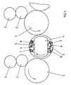
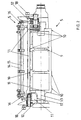
- einen Bogenführungszylinder (Vorderansicht)
- Fig. 3
- ein Bogenhaltesystem (Seitenansicht).
- Fig. 1
- a sheet guide cylinder as a turning device between two printing units (side view)
- Fig. 2
- a sheet guide cylinder (front view)
- Fig. 3
- a sheet retention system (side view).
In einer bogenverarbeitenden Offsetrotationsdruckmaschine in
Reihenbauweise ist zwischen zwei Druckwerken ein Bogenführungszylinder
4 als Wendeeinrichtung angeordnet. Das in
Bogenlaufrichtung vorgeordnete erste Druckwerk ist durch
einen Druckzylinder 1 als Bogenführungszylinder, einen Gummituchzylinder
2 und einen Plattenzylinder 3 gebildet. Analog
ist das in Bogenlaufrichtung dem Bogenführungszylinder 4
nachgeordnete zweite Druckwerk durch einen Druckzylinder 1
als Bogenführungszylinder, einen Gummituchzylinder 2 und
einen Plattenzylinder 3 gebildet.In a sheet-fed offset rotary printing press in
Series construction is a sheet guiding cylinder between two
Die Platten- und Gummituchzylinder 2, 3 sind einfachgroß
(Eintourenwelle) und die Druckzylinder 1 sowie der Bogenführungszylinder
4 als Wendetrommel sind doppeltgroß ausgebildet.
Ein Bogenführungszylinder 4 gem. Fig. 2 besteht aus einem in
einer Zylinderachse 13 symmetrischen Zylindergrundkörper 9,
welcher bevorzugt als einteiliger Trommelkörper mit Achszapfen
ausgeführt ist. Innerhalb des Trommelumfanges des Bogenführungszylinders
4 sind in Bezug zur Zylinderachse 13 mehrere
planparallele Teilflächen 10 als Auflage in einer Ebene
für je eine noch näher beschriebene Platine 11 angeordnet.
Alternativ können die Teilflächen 10 durch je eine volle
Fläche 10 als Auflage gebildet sein. In Fig. 2 sind über die
Breite des Zylindergrundkörpers 9 verteilt angeordnet vier
Teilflächen 10 gezeigt. Alternativ kann der Zylindergrundkörper
9 ebenso mit nur einer entsprechend dimensionierten
Teilfläche 10 pro Platine 11 ausgebildet sein.The plate and
In Fig. 2 sind Teilflächen 10 umfangsseitig symmetrisch auf
jeweils einer Hälfte des Bogenführungszylinders 4 um 180°
versetzt angeordnet. Bei mehrfacher Anordnung der Teilflächen
10 fluchten diese planparallel zur Zylinderachse 13 in jeder
Hälfte (bei doppeltgroßer Ausbildung) in zumindestens einer
Ebene. In den Fig. 2 und 3 ist aus Gründen der Übersichtlichkeit
lediglich eine am Zylindergrundkörper 9 angeordnete
Platine 11 mit einem Bogenhaltesystem 5 gezeigt.2,
Der Bogenführungzylinder 4 als Wendeeinrichtung trägt umfangseitig
auf jeweils einer Hälfte zwei diametral 180° versetzt
angeordnete Bogenhaltesysteme 5. Ein Bogenhaltesystem 5
besteht im vorliegenden Beispiel aus einem Saugersystem 8 mit
schwenkbarem Saugerrohr, einem ersten Greifersystem 6 (Widerdruckgreifer)
und einem zweiten Greifersystem 7 (Schöndruckgreifer)
mit entsprechenden Greiferwellen 14 mit Rollenhebeln
sowie Kurvenrollen 18 und Greiferauflagen und zugeordneten
Steuerkurven für die Greiferwellensteuerung auf. Jedes Bogenhaltesystem
5 weist weiterhin Schwenkwellen 15 mit Steuerkurven
für die entsprechende Schwenkwellensteuerung der Greifersysteme
6, 7 sowie einen Bewegungsmechanismus, z.B. ein
Kurven- oder Koppelgetriebe, für das Saugersystem 8 auf, um
die Übergabe der Bogen zwischen den bogenführenden Zylindern
sowie die inneren Bogenübergaben auf dem Bogenführungszylinder
4 selbst zu realisieren.The
Jedes Bogenhaltesystem 5 ist komplett auf der bereits erwähnten
Platine 11 in Lagerungen 16 angeordnet, so daß diese
Kombination eine Baugruppe darstellt. Jede Platine 11 ist mit
der Unterseite lösbar formschlüssig an den Teilflächen 10 mit
dem Zylindergrundkörper 9 verbunden und trägt beidseitig (in
Achsrichtung der Bogenhaltesysteme 5) jeweils endseitig ein
Seitenteil 12, welches an der Platine 11 fest angeordnet ist
und zumindest teilweise die Lagerstellen der Rollenhebel mit
Kurvenrolle 18 aufnehmen. Die die Greifersysteme 6,7 tragenden
Schwenkwellen 15 sind in den Lagerungen 16 drehbar aufgenommen,
welche auf der Oberseite der Platine 11 angeordnet
sind. Die Seitenteile 12 sind entweder nicht lösbar, zum
Beispiel angegosssen bzw. angeschweißt, oder bevorzugt lösbar,
zum Beispiel verschraubt, mit der Platine 11 verbunden
und tragen die Steuerung der Greifersysteme 6, 7 und des
Saugersystems 8 und der Schwenkwellen 15, einschließlich
Kurvenrollen 18, die dann in bekannter Weise über Steuerkurven
(Kurvengetriebe) steuerbar sind.Each
An der Unterseite der Platine 11 ist wenigstens eine, bevorzugt
sind mehrere Teilflächen 10 angeordnet, welche den am
Zylindergrundkörper 9 angeordneten Teilflächen 10 benachbart
zugeordnet sind. Je nach Ausbildung ist auch eine Kombination
von voller Fläche 10 und Teilflächen 10 bzw. von zwei vollen
Flächen 10 am Zylindergrundkörper 9 bzw. Platine 11 realisierbar.
Die Teilflächen 10 von Zylindergrundkörper 9 und
Unterseite der Platine 11 sind zumindest in einer Ebene
angeordnet. In einer bevorzugten Ausbildung ist die Platine
11 und/oder das entsprechende Seitenteil 12 in einer weiteren
Ebene am Zylindergrundkörper 9 lagerbar. Hierzu sind ebenso
planparallel zur Zylinderachse 13 eine oder mehrere Zusatzflächen
17 anordbar (Fig. 2). Die Zusatzfläche 17 ist dabei
am Zylindergrundkörper 9 und an der benachbart zugeordneten
Unterseite der Platine 11 bzw. des Seitenteils 12 angeordnet.
Die Platine 11 ist stets innerhalb des Zylinderumfanges
angeordnet und stützt sich bei Bedarf an den Zusatzflächen 17
ab.At least one is preferred on the underside of the
Mit der erfingungsgemäßen Ausbildung sind somit auf einer
Platine 11 die Greifersysteme 6,7 und das Saugersystem 8
sowie die Schwenkwellen 15 mit Lagerungen 16, die zur Lagerung
erforderlichen Seitenteile 12 sowie die für die Steuerung
erforderlichen Kurvenrollen 18 mit Rollenhebel sowie
Rückholsysteme (Federn), Anschlagelemente, Schmierungsaggregate
und Axialführungselemente anordbar.
Bei einer Montage ist somit die derart bestückte Platine 11
mit dem Zylindergrundkörper 9 zum Bogenführungszylinder 4
komplettierbar. Bei einer Demontage lassen sich die einzelnen
Bauteile, zum Beispiel die Greiferwelle 14, von der Platine
11 austauschen oder die komplett bestückte Platine 11 wird
bevorzugt vom Zylindergrundkörper 9 getrennt. Die Schnittstelle
bezüglich der Trennung zwischen Platine 11 mit Bogenhaitesystemen
5 und der Steuerung ist dabei zwischen den noch
auf der Platine 11 angeordneten Kurvenrollen 18 (Teil des
Bogenhaltesystems 5) und den zugeordneten Steuerkurven definiert.With the training according to the invention are thus on one
Die beschriebene Ausführung ist nicht auf einen zweifachgroßen
Bogenführungszylinder 4 mit zwei umfangsseitig angeordneten
Platinen 11 mit Bogenhaltesystemen 5 beschränkt.The design described is not a double size
Vielmehr eignet sich diese Lösung auch für einen Zylindergrundkörper
9, beispielsweise einen einfachgroßen Bogenführungszylinder
4, mit nur einer Platine 11 und einem Bogenhaltesystem
5 am Umfang.
Alternativ sind auch drei- oder vierfachgroße Bogenführungszylinder
4 mit entsprechender Anzahl von symmetrisch am
Umfang angeordenten Platinen 11 mit Bogenhaltesystemen 5
ausführbar.
Bei einem Bogenführungszylinder 4 mit einer Platine 11 mit
Bogenhaltesystem 5 ist am Zylindergrundkörper 9 zumindest
eine Fläche bzw. Teilfläche 10 angeordnet, so daß die Platine
11 mit der Unterseite (Fläche bzw. Teilfläche 10) lösbar
innerhalb des Trommelumfanges fixiert ist.
Bei einem Bogenführungszylinder 4 mit mehreren Platinen 11
mit je einem Bogenhaltesystem 5 sind am Zylindergrundkörper 9
mehrere Flächen bzw. Teilflächen 10 symmetrisch um 120° (bei
drei Platinen 11) bzw. um 90° (bei vier Platinen 11) umfangseitig
angeordnet, so daß die Platinen 11 mit der Unterseite
(Fläche bzw. Teilfläche 10) lösbar am Zylindergrundkörper 9
innerhalb des Trommelumfanges fixierbar sind.Rather, this solution is also suitable for a
Alternatively, triple or quadruple-sized
In a
In a
Beispielsweise kann auf einer Platine 11 lediglich ein, z.B.
als Schöndruckgreifer, ausgebildetes Greifersystem 7 mit
einer gelagerten Greiferwelle 14 und wenigstens einer Kurvenrolle
18 angeordnet sein. Alternativ kann auf einer Platine
11 ein erstes und ein zweites Greifersystem 6,7 jeweils mit
Greiferwelle 14 und zugeordneten Kurvenrollen 18 mit Schwenkwellen
15 (oder einem vergleichbaren Schwenkmechanismus) und
zugeordneten Kurvenrollen 18 angeordnet sein.
Ebenso kann zusätzlich zu den Greifersystemen 6,7 (einschließlich
Schwenkmechanismus) zumindest ein gelagertes
Saugersystem 8 mit entsprechendem Bewegungsmechanismus und
zugeordnter Kurvenrolle 18 angeordnet sein. Die Kurvenrollen
18 sind wiederum mit Steuerkurven in Funktionsverbindung.For example, only one
Likewise, in addition to the
Das Bogenhaltesystem 5 ist zumindest durch ein Greifersystem
6 und/oder 7 gebildet, wobei wenigstens ein Greifersystem 6,7
an der Paarungsstelle von zugehöriger Kurvenrolle 18 und
zugeordneter Steuerkurve vom Zylindergrundkörper 9 trennbar
ist.
In Weiterbildung weist dieses Bogenhaltesystem 5 zumindest
ein Saugersystem 8 auf, wobei die Saugersysteme 8 an den
Paarungsstellen von Kurvenrolle 18 und zugeordneter Steuerkurve
vom Zylindergrundkörper 9 trennbar sind. The
In a further development, this
- 1 -1 -
- Druckzylinderpressure cylinder
- 2 -2 -
- GummituchzylinderBlanket cylinder
- 3 -3 -
- Plattenzylinderplate cylinder
- 4 -4 -
- BogenführungszylinderSheet guiding cylinder
- 5 -5 -
- BogenhaltesystemSheet holding system
- 6 -6 -
- erstes Greifersystemfirst gripper system
- 7 -7 -
- zweites Greifersystemsecond gripper system
- 8 -8th -
- Saugersystemsuction system
- 9 -9 -
- ZylindergrundkörperCylinder body
- 10 -10 -
- Fläche/TeilflächeSurface / partial surface
- 11 -11 -
- Platinecircuit board
- 12 -12 -
- Seitenteilside panel
- 13 -13 -
- Zylinderachsecylinder axis
- 14 -14 -
- Greiferwellegripper shaft
- 15 -15 -
- Schwenkwellepivot shaft
- 16 -16 -
- Lagerungstorage
- 17 -17 -
- Zusatzflächeadditional area
- 18 -18 -
- Kurvenrollefollower
Claims (6)
- Sheet guiding cylinder (4) for a rotary printing press with an exchangeable sheet holding system (5) arranged at the periphery with cam roller (18) and fitted control cam for the movement sequence, wherein the sheet guiding cylinder (4) has a cylinder base body (9) with a cylinder axis (13) and relative to the cylinder axis (13) a plane parallel surface/partial surface (10) arranged in a plane, wherein on this surface/partial surface (10) is releasably arranged a platen (11) having on its upper side at least one sheet holding system (5) with the lower side within the cylinder periphery and wherein each sheet holding system (5) is separable at the pairing position of cam roller (18) and fitted control cam from the cylinder base body (9).
- Sheet guiding cylinder according to Claim 1, characterised in that the cylinder base body (9) has on its periphery symmetrically relative to the cylinder axis (13) several plane parallel surfaces/partial surfaces (10) and that against each surface/partial surface (10) there is releasably arranged in each case a platen (11) having at least a sheet holding system (5) with the underside within the cylinder periphery.
- Sheet guiding cylinder according to Claim 1, characterised in that the sheet holding system (5) has at least one gripper system (6, 7) wherein the gripper systems (6, 7) are separable at in each case a pairing position of cam roller (18) and coordinated control cam from the cylinder base body (9).
- Sheet guiding cylinder according to Claim 1, characterised in that the sheet holding system (5) has at least one sucker system (8), wherein the sucker systems (8) are separable at in each case a pairing position of cam roller (18) and coordinated control cam from the cylinder base body (9).
- Sheet guiding cylinder according to at least Claim 1, characterised in that on the platen (11) on both sides in each case in the axial direction of the sheet holding systems on the end sides, side parts (12) are arranged which receive the bearing positions of the roller levers with cam roller (18).
- Sheet guiding cylinder according to at least Claim 1 and 5, characterised in that the cylinder base body (9) has at least one additional surface (17) arranged in plane parallel to the cylinder axis (13) against which the underside of the platen (11) and/or of the side part (12) can be supported additionally within the cylinder periphery.
Applications Claiming Priority (2)
| Application Number | Priority Date | Filing Date | Title |
|---|---|---|---|
| DE19934526 | 1999-07-22 | ||
| DE19934526A DE19934526A1 (en) | 1999-07-22 | 1999-07-22 | Sheet guide cylinder for a rotary printing machine |
Publications (2)
| Publication Number | Publication Date |
|---|---|
| EP1070582A1 EP1070582A1 (en) | 2001-01-24 |
| EP1070582B1 true EP1070582B1 (en) | 2003-05-21 |
Family
ID=7915763
Family Applications (1)
| Application Number | Title | Priority Date | Filing Date |
|---|---|---|---|
| EP00114813A Expired - Lifetime EP1070582B1 (en) | 1999-07-22 | 2000-07-11 | Sheet guiding cylinder for a rotary press |
Country Status (4)
| Country | Link |
|---|---|
| EP (1) | EP1070582B1 (en) |
| JP (1) | JP3410066B2 (en) |
| AT (1) | ATE240836T1 (en) |
| DE (2) | DE19934526A1 (en) |
Family Cites Families (8)
| Publication number | Priority date | Publication date | Assignee | Title |
|---|---|---|---|---|
| DD53711A (en) * | ||||
| DE191658C (en) * | ||||
| DD110452A1 (en) * | 1974-03-21 | 1974-12-20 | ||
| EP0073955B1 (en) * | 1981-09-04 | 1985-11-13 | Motter Printing Press Co. | Gripper for sheet handling equipment |
| DE3428668A1 (en) * | 1984-08-03 | 1986-02-13 | Heidelberger Druckmaschinen Ag, 6900 Heidelberg | DEVICE DRUM FOR SHEET PRINTING MACHINES, ESPECIALLY CARDBOARD MACHINES |
| DE3602084A1 (en) * | 1986-01-24 | 1987-07-30 | Heidelberger Druckmasch Ag | BOW TRANSFER DRUM BETWEEN THE PRINTING UNITS OF ROTATIONAL PRINTING MACHINES |
| DE3614565A1 (en) * | 1986-04-29 | 1987-11-05 | Roland Man Druckmasch | REVERSE DRUM IN ARC ROTATION PRINTING MACHINES |
| DE19650012A1 (en) * | 1996-12-03 | 1998-06-04 | Kba Planeta Ag | Gripper actuation system |
-
1999
- 1999-07-22 DE DE19934526A patent/DE19934526A1/en not_active Ceased
-
2000
- 2000-07-11 AT AT00114813T patent/ATE240836T1/en not_active IP Right Cessation
- 2000-07-11 EP EP00114813A patent/EP1070582B1/en not_active Expired - Lifetime
- 2000-07-11 DE DE50002241T patent/DE50002241D1/en not_active Expired - Lifetime
- 2000-07-21 JP JP2000221417A patent/JP3410066B2/en not_active Expired - Fee Related
Also Published As
| Publication number | Publication date |
|---|---|
| JP3410066B2 (en) | 2003-05-26 |
| ATE240836T1 (en) | 2003-06-15 |
| DE50002241D1 (en) | 2003-06-26 |
| DE19934526A1 (en) | 2001-02-08 |
| EP1070582A1 (en) | 2001-01-24 |
| JP2001063000A (en) | 2001-03-13 |
Similar Documents
| Publication | Publication Date | Title |
|---|---|---|
| EP3043994B1 (en) | Printing press for security printing as well as a method for exchanging a printing plate and for a press start-up | |
| DE10156800B4 (en) | printing unit | |
| EP3043997B1 (en) | Method and device for adjusting ink carrying rotary bodies of a printing press | |
| EP0290853A2 (en) | Bearing for a printing unit cylinder | |
| DE102013214784B4 (en) | Device for correcting trapezoidal register deviations | |
| EP1511631B1 (en) | Inking system for flexographic printing presses | |
| EP1710081A2 (en) | Printing machine, in particular sheet printing machine | |
| EP0924069B1 (en) | Sheet guiding device in a printing machine | |
| EP1070582B1 (en) | Sheet guiding cylinder for a rotary press | |
| DE3508699A1 (en) | HEIGHT-ADJUSTABLE GRIPPER PADS FOR REVERSE DRUM GRIPPERS IN REVERSIBLE DRUMS OF BEAUTIFUL AND REPRINTING MACHINES | |
| EP0243737A2 (en) | Sheet-turning cylinder for a rotary sheet-printing machine | |
| EP0085752B1 (en) | Printing unit for a rotary offset machine | |
| DE19954390C1 (en) | Pneumatic sheet feed to a printing press has an outer tube section and a rotating concentric inner tubular section both fitted with control openings which are opened and closed by the rotation of the inner part to allow air through | |
| DE4433999C2 (en) | Sheet guiding drum for rotary printing machines | |
| EP1732760B1 (en) | Printing mechanism of a printing machine having a pressure roller | |
| DE2926765A1 (en) | DEVICE FOR SUPPRESSING BENDING VIBRATIONS IN ROTATIONAL OFFSET PRINTING MACHINES | |
| DE2945192C2 (en) | Offset printing machine | |
| DE19854053A1 (en) | Sheet guiding unit for a printing press that incorporates a support bearing set on an interior wall of a side frame, the unit is set in a releasable or frictionally interlocked fashion | |
| DE10119140A1 (en) | Printing and coating machine for processing printed sheets uses a modular run, a counter-pressure cylinder, a cylinder to adjust to it with tools to handle sheets of printed material and a circumferential register adjuster. | |
| DE19941633A1 (en) | Method for fitting and changing suction rings on suction roller in printing machine is carried out in a preinstallation section after which roller is fitted back into position in machine | |
| DE1159471B (en) | Device for setting different sheet thicknesses in a rotary sheet printing machine for multi-color printing | |
| EP1005982A1 (en) | Device for exchanging rollers and cylinders in a printing press | |
| EP1088655A1 (en) | Actuatable gripper system for a sheet guiding cylinder in a rotary press | |
| DE102022102028A1 (en) | Processing unit and method for operating a processing unit of a processing machine | |
| DE102014115870A1 (en) | Decoupled gripper control |
Legal Events
| Date | Code | Title | Description |
|---|---|---|---|
| PUAI | Public reference made under article 153(3) epc to a published international application that has entered the european phase |
Free format text: ORIGINAL CODE: 0009012 |
|
| AK | Designated contracting states |
Kind code of ref document: A1 Designated state(s): AT BE CH CY DE DK ES FI FR GB GR IE IT LI LU MC NL PT SE |
|
| AX | Request for extension of the european patent |
Free format text: AL;LT;LV;MK;RO;SI |
|
| 17P | Request for examination filed |
Effective date: 20001206 |
|
| 17Q | First examination report despatched |
Effective date: 20010802 |
|
| AKX | Designation fees paid |
Free format text: AT BE CH CY DE DK ES FI FR GB GR IE IT LI LU MC NL PT SE |
|
| GRAH | Despatch of communication of intention to grant a patent |
Free format text: ORIGINAL CODE: EPIDOS IGRA |
|
| GRAH | Despatch of communication of intention to grant a patent |
Free format text: ORIGINAL CODE: EPIDOS IGRA |
|
| GRAA | (expected) grant |
Free format text: ORIGINAL CODE: 0009210 |
|
| AK | Designated contracting states |
Designated state(s): AT BE CH CY DE DK ES FI FR GB GR IE IT LI LU MC NL PT SE |
|
| PG25 | Lapsed in a contracting state [announced via postgrant information from national office to epo] |
Ref country code: IT Free format text: LAPSE BECAUSE OF FAILURE TO SUBMIT A TRANSLATION OF THE DESCRIPTION OR TO PAY THE FEE WITHIN THE PRESCRIBED TIME-LIMIT;WARNING: LAPSES OF ITALIAN PATENTS WITH EFFECTIVE DATE BEFORE 2007 MAY HAVE OCCURRED AT ANY TIME BEFORE 2007. THE CORRECT EFFECTIVE DATE MAY BE DIFFERENT FROM THE ONE RECORDED. Effective date: 20030521 Ref country code: IE Free format text: LAPSE BECAUSE OF NON-PAYMENT OF DUE FEES Effective date: 20030521 Ref country code: NL Free format text: LAPSE BECAUSE OF FAILURE TO SUBMIT A TRANSLATION OF THE DESCRIPTION OR TO PAY THE FEE WITHIN THE PRESCRIBED TIME-LIMIT Effective date: 20030521 Ref country code: FI Free format text: LAPSE BECAUSE OF FAILURE TO SUBMIT A TRANSLATION OF THE DESCRIPTION OR TO PAY THE FEE WITHIN THE PRESCRIBED TIME-LIMIT Effective date: 20030521 Ref country code: FR Free format text: LAPSE BECAUSE OF NON-PAYMENT OF DUE FEES Effective date: 20030521 |
|
| REG | Reference to a national code |
Ref country code: GB Ref legal event code: FG4D Free format text: NOT ENGLISH |
|
| REG | Reference to a national code |
Ref country code: CH Ref legal event code: EP |
|
| GBT | Gb: translation of ep patent filed (gb section 77(6)(a)/1977) |
Effective date: 20030521 |
|
| REG | Reference to a national code |
Ref country code: IE Ref legal event code: FG4D Free format text: GERMAN |
|
| REF | Corresponds to: |
Ref document number: 50002241 Country of ref document: DE Date of ref document: 20030626 Kind code of ref document: P |
|
| PG25 | Lapsed in a contracting state [announced via postgrant information from national office to epo] |
Ref country code: LU Free format text: LAPSE BECAUSE OF NON-PAYMENT OF DUE FEES Effective date: 20030711 Ref country code: CY Free format text: LAPSE BECAUSE OF FAILURE TO SUBMIT A TRANSLATION OF THE DESCRIPTION OR TO PAY THE FEE WITHIN THE PRESCRIBED TIME-LIMIT Effective date: 20030711 |
|
| PG25 | Lapsed in a contracting state [announced via postgrant information from national office to epo] |
Ref country code: BE Free format text: LAPSE BECAUSE OF NON-PAYMENT OF DUE FEES Effective date: 20030731 Ref country code: MC Free format text: LAPSE BECAUSE OF NON-PAYMENT OF DUE FEES Effective date: 20030731 |
|
| PG25 | Lapsed in a contracting state [announced via postgrant information from national office to epo] |
Ref country code: DK Free format text: LAPSE BECAUSE OF FAILURE TO SUBMIT A TRANSLATION OF THE DESCRIPTION OR TO PAY THE FEE WITHIN THE PRESCRIBED TIME-LIMIT Effective date: 20030821 Ref country code: SE Free format text: LAPSE BECAUSE OF FAILURE TO SUBMIT A TRANSLATION OF THE DESCRIPTION OR TO PAY THE FEE WITHIN THE PRESCRIBED TIME-LIMIT Effective date: 20030821 Ref country code: PT Free format text: LAPSE BECAUSE OF FAILURE TO SUBMIT A TRANSLATION OF THE DESCRIPTION OR TO PAY THE FEE WITHIN THE PRESCRIBED TIME-LIMIT Effective date: 20030821 Ref country code: GR Free format text: LAPSE BECAUSE OF FAILURE TO SUBMIT A TRANSLATION OF THE DESCRIPTION OR TO PAY THE FEE WITHIN THE PRESCRIBED TIME-LIMIT Effective date: 20030821 |
|
| PG25 | Lapsed in a contracting state [announced via postgrant information from national office to epo] |
Ref country code: ES Free format text: LAPSE BECAUSE OF FAILURE TO SUBMIT A TRANSLATION OF THE DESCRIPTION OR TO PAY THE FEE WITHIN THE PRESCRIBED TIME-LIMIT Effective date: 20030901 |
|
| NLV1 | Nl: lapsed or annulled due to failure to fulfill the requirements of art. 29p and 29m of the patents act | ||
| REG | Reference to a national code |
Ref country code: IE Ref legal event code: FD4D Ref document number: 1070582E Country of ref document: IE |
|
| BERE | Be: lapsed |
Owner name: *MAN ROLAND DRUCKMASCHINEN A.G. Effective date: 20030731 |
|
| PLBE | No opposition filed within time limit |
Free format text: ORIGINAL CODE: 0009261 |
|
| STAA | Information on the status of an ep patent application or granted ep patent |
Free format text: STATUS: NO OPPOSITION FILED WITHIN TIME LIMIT |
|
| 26N | No opposition filed |
Effective date: 20040224 |
|
| EN | Fr: translation not filed | ||
| PG25 | Lapsed in a contracting state [announced via postgrant information from national office to epo] |
Ref country code: GB Free format text: LAPSE BECAUSE OF NON-PAYMENT OF DUE FEES Effective date: 20040711 |
|
| PG25 | Lapsed in a contracting state [announced via postgrant information from national office to epo] |
Ref country code: CH Free format text: LAPSE BECAUSE OF NON-PAYMENT OF DUE FEES Effective date: 20040731 Ref country code: LI Free format text: LAPSE BECAUSE OF NON-PAYMENT OF DUE FEES Effective date: 20040731 |
|
| GBPC | Gb: european patent ceased through non-payment of renewal fee |
Effective date: 20040711 |
|
| REG | Reference to a national code |
Ref country code: CH Ref legal event code: PL |
|
| PGFP | Annual fee paid to national office [announced via postgrant information from national office to epo] |
Ref country code: AT Payment date: 20080715 Year of fee payment: 9 |
|
| PG25 | Lapsed in a contracting state [announced via postgrant information from national office to epo] |
Ref country code: AT Free format text: LAPSE BECAUSE OF NON-PAYMENT OF DUE FEES Effective date: 20090711 |
|
| PGFP | Annual fee paid to national office [announced via postgrant information from national office to epo] |
Ref country code: DE Payment date: 20110722 Year of fee payment: 12 |
|
| REG | Reference to a national code |
Ref country code: DE Ref legal event code: R081 Ref document number: 50002241 Country of ref document: DE Owner name: MANROLAND SHEETFED GMBH, DE Free format text: FORMER OWNER: MANROLAND AG, 63075 OFFENBACH, DE Effective date: 20120509 |
|
| PG25 | Lapsed in a contracting state [announced via postgrant information from national office to epo] |
Ref country code: DE Free format text: LAPSE BECAUSE OF NON-PAYMENT OF DUE FEES Effective date: 20130201 |
|
| REG | Reference to a national code |
Ref country code: DE Ref legal event code: R119 Ref document number: 50002241 Country of ref document: DE Effective date: 20130201 |