EP1070165B1 - Verfahren zum Ansteuern des Antriebsmotors eines Kondensationswäschetrockners - Google Patents
Verfahren zum Ansteuern des Antriebsmotors eines Kondensationswäschetrockners Download PDFInfo
- Publication number
- EP1070165B1 EP1070165B1 EP00909131A EP00909131A EP1070165B1 EP 1070165 B1 EP1070165 B1 EP 1070165B1 EP 00909131 A EP00909131 A EP 00909131A EP 00909131 A EP00909131 A EP 00909131A EP 1070165 B1 EP1070165 B1 EP 1070165B1
- Authority
- EP
- European Patent Office
- Prior art keywords
- rotation
- cooling air
- fan
- drive motor
- process air
- Prior art date
- Legal status (The legal status is an assumption and is not a legal conclusion. Google has not performed a legal analysis and makes no representation as to the accuracy of the status listed.)
- Expired - Lifetime
Links
- 238000000034 method Methods 0.000 title claims abstract description 62
- 238000009833 condensation Methods 0.000 title abstract description 15
- 230000005494 condensation Effects 0.000 title abstract description 15
- 238000001816 cooling Methods 0.000 claims abstract description 39
- 238000001035 drying Methods 0.000 claims abstract description 33
- 238000010438 heat treatment Methods 0.000 claims abstract description 15
- 238000005259 measurement Methods 0.000 claims 5
- 238000005452 bending Methods 0.000 claims 1
- 238000005265 energy consumption Methods 0.000 abstract description 3
- 238000010276 construction Methods 0.000 abstract 1
- 238000005406 washing Methods 0.000 abstract 1
- 238000001595 flow curve Methods 0.000 description 3
- 238000010792 warming Methods 0.000 description 3
- 230000002441 reversible effect Effects 0.000 description 2
- 230000015572 biosynthetic process Effects 0.000 description 1
- 238000007791 dehumidification Methods 0.000 description 1
- 238000011161 development Methods 0.000 description 1
- 230000018109 developmental process Effects 0.000 description 1
- 238000010409 ironing Methods 0.000 description 1
- 238000004519 manufacturing process Methods 0.000 description 1
Images
Classifications
-
- D—TEXTILES; PAPER
- D06—TREATMENT OF TEXTILES OR THE LIKE; LAUNDERING; FLEXIBLE MATERIALS NOT OTHERWISE PROVIDED FOR
- D06F—LAUNDERING, DRYING, IRONING, PRESSING OR FOLDING TEXTILE ARTICLES
- D06F58/00—Domestic laundry dryers
- D06F58/20—General details of domestic laundry dryers
-
- D—TEXTILES; PAPER
- D06—TREATMENT OF TEXTILES OR THE LIKE; LAUNDERING; FLEXIBLE MATERIALS NOT OTHERWISE PROVIDED FOR
- D06F—LAUNDERING, DRYING, IRONING, PRESSING OR FOLDING TEXTILE ARTICLES
- D06F2103/00—Parameters monitored or detected for the control of domestic laundry washing machines, washer-dryers or laundry dryers
- D06F2103/02—Characteristics of laundry or load
- D06F2103/08—Humidity
-
- D—TEXTILES; PAPER
- D06—TREATMENT OF TEXTILES OR THE LIKE; LAUNDERING; FLEXIBLE MATERIALS NOT OTHERWISE PROVIDED FOR
- D06F—LAUNDERING, DRYING, IRONING, PRESSING OR FOLDING TEXTILE ARTICLES
- D06F2103/00—Parameters monitored or detected for the control of domestic laundry washing machines, washer-dryers or laundry dryers
- D06F2103/02—Characteristics of laundry or load
- D06F2103/08—Humidity
- D06F2103/10—Humidity expressed as capacitance or resistance
-
- D—TEXTILES; PAPER
- D06—TREATMENT OF TEXTILES OR THE LIKE; LAUNDERING; FLEXIBLE MATERIALS NOT OTHERWISE PROVIDED FOR
- D06F—LAUNDERING, DRYING, IRONING, PRESSING OR FOLDING TEXTILE ARTICLES
- D06F2103/00—Parameters monitored or detected for the control of domestic laundry washing machines, washer-dryers or laundry dryers
- D06F2103/28—Air properties
- D06F2103/32—Temperature
-
- D—TEXTILES; PAPER
- D06—TREATMENT OF TEXTILES OR THE LIKE; LAUNDERING; FLEXIBLE MATERIALS NOT OTHERWISE PROVIDED FOR
- D06F—LAUNDERING, DRYING, IRONING, PRESSING OR FOLDING TEXTILE ARTICLES
- D06F2103/00—Parameters monitored or detected for the control of domestic laundry washing machines, washer-dryers or laundry dryers
- D06F2103/28—Air properties
- D06F2103/36—Flow or velocity
-
- D—TEXTILES; PAPER
- D06—TREATMENT OF TEXTILES OR THE LIKE; LAUNDERING; FLEXIBLE MATERIALS NOT OTHERWISE PROVIDED FOR
- D06F—LAUNDERING, DRYING, IRONING, PRESSING OR FOLDING TEXTILE ARTICLES
- D06F2105/00—Systems or parameters controlled or affected by the control systems of washing machines, washer-dryers or laundry dryers
- D06F2105/16—Air properties
- D06F2105/24—Flow or velocity
-
- D—TEXTILES; PAPER
- D06—TREATMENT OF TEXTILES OR THE LIKE; LAUNDERING; FLEXIBLE MATERIALS NOT OTHERWISE PROVIDED FOR
- D06F—LAUNDERING, DRYING, IRONING, PRESSING OR FOLDING TEXTILE ARTICLES
- D06F2105/00—Systems or parameters controlled or affected by the control systems of washing machines, washer-dryers or laundry dryers
- D06F2105/32—Air flow control means
-
- D—TEXTILES; PAPER
- D06—TREATMENT OF TEXTILES OR THE LIKE; LAUNDERING; FLEXIBLE MATERIALS NOT OTHERWISE PROVIDED FOR
- D06F—LAUNDERING, DRYING, IRONING, PRESSING OR FOLDING TEXTILE ARTICLES
- D06F2105/00—Systems or parameters controlled or affected by the control systems of washing machines, washer-dryers or laundry dryers
- D06F2105/46—Drum speed; Actuation of motors, e.g. starting or interrupting
-
- D—TEXTILES; PAPER
- D06—TREATMENT OF TEXTILES OR THE LIKE; LAUNDERING; FLEXIBLE MATERIALS NOT OTHERWISE PROVIDED FOR
- D06F—LAUNDERING, DRYING, IRONING, PRESSING OR FOLDING TEXTILE ARTICLES
- D06F58/00—Domestic laundry dryers
- D06F58/02—Domestic laundry dryers having dryer drums rotating about a horizontal axis
- D06F58/04—Details
- D06F58/08—Driving arrangements
-
- D—TEXTILES; PAPER
- D06—TREATMENT OF TEXTILES OR THE LIKE; LAUNDERING; FLEXIBLE MATERIALS NOT OTHERWISE PROVIDED FOR
- D06F—LAUNDERING, DRYING, IRONING, PRESSING OR FOLDING TEXTILE ARTICLES
- D06F58/00—Domestic laundry dryers
- D06F58/32—Control of operations performed in domestic laundry dryers
- D06F58/34—Control of operations performed in domestic laundry dryers characterised by the purpose or target of the control
- D06F58/36—Control of operational steps, e.g. for optimisation or improvement of operational steps depending on the condition of the laundry
- D06F58/38—Control of operational steps, e.g. for optimisation or improvement of operational steps depending on the condition of the laundry of drying, e.g. to achieve the target humidity
-
- D—TEXTILES; PAPER
- D06—TREATMENT OF TEXTILES OR THE LIKE; LAUNDERING; FLEXIBLE MATERIALS NOT OTHERWISE PROVIDED FOR
- D06F—LAUNDERING, DRYING, IRONING, PRESSING OR FOLDING TEXTILE ARTICLES
- D06F58/00—Domestic laundry dryers
- D06F58/32—Control of operations performed in domestic laundry dryers
- D06F58/34—Control of operations performed in domestic laundry dryers characterised by the purpose or target of the control
- D06F58/48—Control of the energy consumption
-
- Y—GENERAL TAGGING OF NEW TECHNOLOGICAL DEVELOPMENTS; GENERAL TAGGING OF CROSS-SECTIONAL TECHNOLOGIES SPANNING OVER SEVERAL SECTIONS OF THE IPC; TECHNICAL SUBJECTS COVERED BY FORMER USPC CROSS-REFERENCE ART COLLECTIONS [XRACs] AND DIGESTS
- Y02—TECHNOLOGIES OR APPLICATIONS FOR MITIGATION OR ADAPTATION AGAINST CLIMATE CHANGE
- Y02B—CLIMATE CHANGE MITIGATION TECHNOLOGIES RELATED TO BUILDINGS, e.g. HOUSING, HOUSE APPLIANCES OR RELATED END-USER APPLICATIONS
- Y02B40/00—Technologies aiming at improving the efficiency of home appliances, e.g. induction cooking or efficient technologies for refrigerators, freezers or dish washers
Definitions
- the invention relates to a method for controlling the drive motor Condensation clothes dryer with a rotatably mounted drying drum for taking up the laundry to be dried and a blower to promote the drying process required process air and a blower for generating a cooling air flow a heat exchanger for dehumidifying the process air and with a sensor arrangement for Acquisition of measured values in the drying process, the drive motor for changing Rotation directions for the drum drive and the drive of process and cooling air blowers is switchable and the program control device with a device for Control of the drive motor is formed and a condensation dryer for Execution of the procedure.
- So-called single-motor drives are used in condensation tumble dryers. This means that the drum drive as well as the operation of the cooling air and process air blower via a common motor. as a rule, the blowers are straight-bladed or forward-curved impellers that run in spiral casings, realized.
- a condensation clothes dryer is known from EP 328 250 A1, which has two fan wheels with curved fan blades.
- a single drive motor is provided for driving the fan wheels and the drum, which is designed for changing directions of rotation. The direction of rotation is reversed periodically throughout the entire drying process to prevent the laundry items from becoming tangled. Both fan wheels thus promote the optimal volume flow over 90% of the drying time and 10% of the drying time over the entire drying process the reduced volume flow due to the blade design.
- DE 30 39 685 A1 discloses a tumble dryer with a reversible drive Laundry drum known in which a straight-bladed fan for production of the process air volume flow is stored in a symmetrical fan housing is.
- DE 31 35 289 A1 also discloses a condensation tumble dryer with a blower unit known for a cooling air and a process air blower with a single motor.
- the rotary movement of the drum is driven by a separately arranged one Drive motor.
- the fan wheels of cooling air and process air blowers are included in the shown example formed straight-bladed.
- a disadvantage of this known design is that the cooling air blower by the arrangement of the fan blades in the Warming phase when the drying program starts is operated at full power. Thereby is in the heating phase, in which there is still no high moisture discharge from the laundry, a lot of heat is removed from the process air circuit. As a result, the Warming phase and the entire drying process extended and energy consumption is increased.
- the invention therefore presents the problem of a method for controlling the drive motor to design a condensation dryer in such a way that the heating phase in Drying process is shortened and thereby the energy consumption of the whole Drying process is reduced.
- the drive motor is operated for the duration of the heating phase until a predetermined process air temperature value is reached in the wrong direction of rotation for the cooling air blower due to the forwardly curved impeller blades.
- a lower cooling air volume flow is conducted over the heat exchanger. This means that less heat energy is removed from the process air and the heating phase and thus the drying process is shortened overall. This advantageously results in an energy-reduced dry operation.
- condensation tumble dryer according to the invention and the method according to the invention for controlling the drive motor it is also possible to avoid laundry roll-ups, which occur increasingly in single-motor drives with a drive motor mainly operated in the preferred direction of rotation. If the set residual moisture in the laundry is sensed at an early point in the drying program via the device for recording the laundry resistance or the residual moisture in the laundry, it can be concluded that a laundry reel is present or that the laundry does not reach a uniform degree of dryness in the entire laundry item Has. According to the method according to the invention, the preferred direction of rotation of the drive motor is then switched over to the initial direction of rotation.
- the fan design of the process air blower with a straight-bladed fan wheel achieves a uniform process air volume flow when the drive motor runs left or right.
- the cooling air blower is advantageously designed with forward-curved fan blades, as a result of which an optimal volume flow in the direction of rotation correct for the impeller and a reduced volume flow in the direction of rotation incorrect for the impeller is achieved. If the drive motor is operated in the heating phase in the wrong direction of rotation for the cooling air blower (initial direction of rotation), there is less heat discharge from the process air circuit at the heat exchanger. The operation of the cooling air fan in the wrong direction of rotation also enables considerably quieter operation in the heating phase.
- the fan design according to the invention and the control of the drive motor accordingly enable a shorter heating-up phase and thus an energy-reduced and an acoustically quieter drying process.
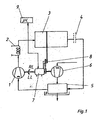
- FIG. 1 shows a schematic representation of the process air circuit and cooling air duct in FIG shown a condensation dryer.
- the process air is generated using a process air blower (1) over the heating device (2) to the rotatably mounted drum (3). Then the Process air flow via a fluff filter (4) to the heat exchanger (5) Condensation device.
- the process air blower (1) and the cooling air blower (6) is provided with a single drive motor (7).
- the high speed of the drive motor (7) is used to drive the drum (3) via an intermediate drive (8) reduced.
- the speed at the process and cooling air blower (1, 6) corresponds to the motor speed.
- the drive motor (7) is controlled with respect to the speed and direction of rotation Microcomputer (9) of the program control device.
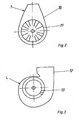
- FIG. 2 shows the process air blower (1) with a symmetrical blower housing (10) and with a blower wheel (11) with a straight blade design.
- This fan design ensures a uniformly high volume flow V ° in both directions of rotation of the drive motor (7).
- FIG. 3 shows the cooling air fan (6) with a spiral fan housing (12) and Fan wheel (13) with forward-curved fan blades.
- This fan formation causes a different volume flow in the directions of rotation of the drive motor (7), because only in one direction of rotation (or in the correct direction of rotation for the cooling air blower (6)) optimal volume flow is generated.
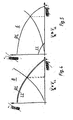
- the volume flow curve is shown in FIG. 5.
- the control of the drive motor to reverse the direction of rotation takes place via the microcomputer (9) of the program control device either time-controlled or depending on temperature. With the time-controlled control, the Reversal of the direction of rotation after a time stored in the non-volatile memory for the Heating phase. There can be several time values for the heating phase in the memory for the Different program selection options (easy-care, colored crockery, etc.) and Drying levels (ironing moisture, cupboard dry, etc.) must be stored.
- the temperature-controlled control for reversing the direction of rotation is the achievement of a Process air temperature values evaluated as a signal to control the direction of rotation reversal.
- the sensors for recording the process air temperature values are in the process air duct arranged at the drum inlet and / or drum outlet for the process air. It will be the Process air temperature value shortly before reaching the so-called equilibrium phase in Drying process used as a threshold.
- the equilibrium phase in the drying process is the phase at which the process air temperature remains almost the same Moisture is discharged from the laundry. This process air temperature value characterizes this End of warming up.
- the drive motor (7) is in this phase in the for Cooling air blower (6) operated in the correct direction of rotation, so that the maximum dehumidification of the Process air takes place via the heat exchanger (5).
- the control of the drive motor (7) for Reversal of the direction of rotation can also depend on the residual moisture content in the Main dry phase or the equilibrium phase take place. Becomes one at this stage senses the set or desired residual moisture content in the laundry at an early stage, it can be concluded that a laundry reel has formed.
- a winder a laundry item referred to, in which the laundry items as laundry bales in the drum be moved.
- the edge area of the laundry item already has that Desired residual moisture content is reached while the core is not yet the desired Has reached the degree of dryness.
- the Drive motor (7) in the opposite direction to the preferred direction of rotation.
Landscapes
- Engineering & Computer Science (AREA)
- Textile Engineering (AREA)
- Control Of Washing Machine And Dryer (AREA)
- Detail Structures Of Washing Machines And Dryers (AREA)
- Control Of Motors That Do Not Use Commutators (AREA)
- Drying Of Solid Materials (AREA)
Description
Für den Antrieb der Gebläseräder und der Trommel ist ein einziger Antriebsmotor vorgesehen, der für wechselnde Drehrichtungen ausgebildet ist. Die Drehrichtungsumkehr erfolgt periodisch im Verlauf des gesamten Trockenprozesses, um ein Verknäulen der Wäschestücke zu verhindern. Beide Gebläseräder fördern dadurch über den gesamten Trockenprozess zu 90% der Trockenzeit den optimalen Volumenstrom und zu 10% der Trockenzeit den durch die Schaufelausbildung bedingten verringerten Volumenstrom.
Bei dem erfindungsgemäß ausgebildeten Kondensationswäschetrockner bestehen weitere Vorteile insbesondere darin, dass durch die Gebläseausbildung des Prozessluftgebläses mit geradschaufligen Gebläserad ein gleichmäßiger Prozessluftvolumenstrom bei Links- oder Rechtslauf des Antriebsmotors erreicht wird. Das Kühlluftgebläse ist vorteilhaft mit vorwärtsgekrümmten Gebläseschaufeln ausgebildet, wodurch ein optimaler Volumenström in der für das Gebläserad richtigen Drehrichtung und ein verringerter Volumenstrom in der für das Gebläserad falschen Drehrichtung erreicht wird. Betreibt man den Antriebsmotor in der Erwärmungshase in der für das Kühlluftgebläse falschen Drehrichtung (Anfangsdrehrichtung), erfolgt ein geringerer Wärmeaustrag aus dem Prozessluftkreislauf am Wärmetauscher. Durch den Betrieb des Kühlluftgebläses in der falschen Drehrichtung wird außerdem ein wesentlich geräuschärmerer Betrieb in der Erwärmungsphase ermöglicht. Durch die erfindungsgemäße Gebläseausbildung sowie die Ansteuerung des Antriebsmotors wird demnach eine kürzere Aufheizphase und damit ein energiereduzierter sowie ein akustisch leiserer Trockenprozess ermöglicht.
- Figur 1
- eine schematische Darstellung von Prozessluftkreislauf und Kühlluftführung in einem Kondensationswäschetrockner,
- Figur 2
- eine schematische Darstellung des Prozessluftgebläses (1) mit geradschaufligem Gebläserad (11) und symmetrischem Gebläsegehäuse (10),
- Figur 3
- eine schematische Darstellung des Kühlluftgebläses (6) mit vorwärtsgekrümmten Gebläseschaufeln am Gebläserad (13) und spiralförmigen Gebläsegehäuse (12),
- Figur 4
- den Volumenstromverlauf bei Rechts- und Linkslauf des Antriebsmotors (7) am Prozessluftgebläse (1),
- Figur 5
- den Volumenstromverlauf bei Rechts- und Linkslauf des Antriebsmotors (7) am Kühlluftgebläse (6).
Claims (8)
- Verfahren zum Ansteuern des Antriebsmotors eines Kondensationswäschetrockners mit einer drehbar gelagerten Trockentrommel (3) zur Aufnahme der zu trocknenden Wäsche und einem Gebläse (1) zur Förderung der für den Trockenvorgang erforderlichen Prozessluft sowie einem Gebläse (6) zur Erzeugung eines Kühlluftstromes über einen Wärmetauscher (5) zum Entfeuchten der Prozessluft sowie mit einer Sensoranordnung zur Erfassung von Messwerten im Trockenprozess, wobei der Antriebsmotor (7) für wechselnde Drehrichtungen für den Trommelantrieb sowie den Antrieb von Prozess- und Kühlluftgebläse umschaltbar ausgebildet ist und die Programmsteuereinrichtung mit einer Einrichtung zur Ansteuerung des Antriebsmotors (7) ausgebildet ist,
dadurch gekennzeichnet, dass der Trockenprozess in der Erwärmphase mit einer Anfangsdrehrichtung des Antriebsmotors (7), welche einen durch die Konstruktion des Kühlluftgebläses (6) bestimmten geringeren Kühlluftvolumenstrom über den Wärmetauscher (5) bewirkt, startet
und dass die Ansteuerung des Antriebsmotors (7) zur Drehrichtungsumkehr von der Anfangsdrehrichtung auf die Vorzugsdrehrichtung mit maximalen Kühlluftvolumenstrom in Abhängigkeit eines in einem nichtflüchtigen Speicher der Programmsteuereinrichtung hinterlegten Zeitwertes und/oder eines von der Sensoranordnung erfassten Messwertes erfolgt. - Verfahren zum Ansteuern des Antriebsmotors nach Anspruch 1,
dadurch gekennzeichnet, dass die Ansteuerung zur Drehrichtungsumkehr in Abhängigkeit eines von der Sensoreinrichtung zur Erfassung der Prozesslufttemperatur erfassten Signals erfolgt, welches das Ende der Erwärmungsphase für den Trockenprozess kennzeichnet. - Verfahren zum Ansteuern des Antriebsmotors nach Anspruch 1,
dadurch gekennzeichnet, dass die Ansteuerung zur Drehrichtungsumkehr zeitgesteuert über die Programmsteuereinrichtung in Abhängigkeit von in einem nichtflüchtigen Speicher hinterlegten Zeitwerten erfolgt. - Verfahren zum Ansteuern des Antriebsmotors nach Anspruch 1 und 3,
dadurch gekennzeichnet, dass die Ansteuerung zur Drehrichtungsumkehr in Abhängigkeit eines von der Sensoreinrichtung zur Erfassung des Widerstandes der Wäsche erfassten Signals in Abhängigkeit der Restfeuchte in der Wäsche erfolgt. - Kondensationswäschetrockner zur Durchführung des Verfahrens zum Ansteuern des Antriebsmotors für den Trockenprozess nach mindestens einem der Ansprüche 1 bis 4, mit einer drehbar gelagerten Trockentrommel (3) zur Aufnahme der zu trocknenden Wäsche und einem Gebläse (1) zur Förderung der für den Trockenvorgang erforderlichen Prozeßluft sowie einem Gebläse (6) zur Erzeugung eines Kühlluftstromes über einen Wärmetauscher (5) zum Entfeuchten der Prozeßluft sowie mit einer Sensoranordnung zur Erfassung von Meßwerten im Trockenprozeß, wobei der Antriebsmotor (7) für wechselnde Drehrichtungen für den Trommelantrieb sowie den Antrieb von Prozeßund Kühlluftgeblase umschaltbar ausgebildet ist und die Programmsteuereinrichtung mit einer Einrichtung zur Ansteuerung des Antriebsmotors (7) ausgebildet ist,
dadurch gekennzeichnet, dass das Prozessluftgebläsegehäuse (10), in dem ein geradschaufliges Gebläserad (11) gelagert ist, symmetrisch ausgebildet ist,
dass das Kühlluftgebläsegehäuse (12), in dem ein Gebläserad (13) mit vorwärtsgekrümmten Gebläseschaufeln gelagert ist, spiralförmig ausgebildet ist,
dass die Vorwärtskrümmung der Gebläseschaufeln sowie das spiralförmige
Gebläsegehäuse (12) die Vorzugsdrehrichtung des Antriebsmotors (7) für einen maximalen Volumenstrom des Kühlluftgebläses (6) bestimmt
und dass die Programmsteuereinrichtung für die temperaturgesteuerte oder zeitgesteuerte und/oder restfeuchtegesteuerte Ansteuerung zur Drehrichtungsumkehr ausgebildet ist,
und dass die Programmiersteuereinrichtung so ausgebildet ist, dass der Trockenprozeß in der Erwärmphase mit einer Anfangsdrehrichtung, welche einen durch die Konstruktion des Kühiluftgebläses (6) bestimmten geringeren Kühlluftvolumenstrom über den Wärmetauscher (5) bewirkt, startet. - Kondensationswäschetrockner nach Anspruch 5,
dadurch gekennzeichnet, dass als Sensoranordnung zur Erfassung von Messwerten im Trockenprozess für die Ansteuerung zur Drehrichtungsumkehr eine Einrichtung zur Erfassung der Prozesslufttemperatur im Prozessluftkanal angeordnet ist. - Kondensationswäschetrockner nach Anspruch 5,
dadurch gekennzeichnet, dass als Sensoranordnung Sensoren zur Erfassung der Prozesslufttemperaturwerte im Prozessluftkanal am Trommeleintritt und Trommelausgang für die Prozessluft angeordnet sind. - Kondensationswäschetrockner nach Anspruch 5,
dadurch gekennzeichnet, dass als Sensoranordnung zur Erfassung von Messwerten im Trockenprozess für die Ansteuerung zur Drehrichtungsumkehr eine Einrichtung zur Erfassung des Widerstandes der Wäsche in Abhängigkeit der Restfeuchte in der Wäsche vorgesehen ist.
Applications Claiming Priority (3)
| Application Number | Priority Date | Filing Date | Title |
|---|---|---|---|
| DE19904993 | 1999-02-08 | ||
| DE19904993A DE19904993C2 (de) | 1999-02-08 | 1999-02-08 | Kondensationswäschetrockner |
| PCT/EP2000/000794 WO2000047810A1 (de) | 1999-02-08 | 2000-02-01 | Kondensationswäschetrockner |
Publications (2)
| Publication Number | Publication Date |
|---|---|
| EP1070165A1 EP1070165A1 (de) | 2001-01-24 |
| EP1070165B1 true EP1070165B1 (de) | 2003-07-09 |
Family
ID=7896737
Family Applications (1)
| Application Number | Title | Priority Date | Filing Date |
|---|---|---|---|
| EP00909131A Expired - Lifetime EP1070165B1 (de) | 1999-02-08 | 2000-02-01 | Verfahren zum Ansteuern des Antriebsmotors eines Kondensationswäschetrockners |
Country Status (6)
| Country | Link |
|---|---|
| EP (1) | EP1070165B1 (de) |
| AT (1) | ATE244787T1 (de) |
| DE (2) | DE19904993C2 (de) |
| ES (1) | ES2199785T3 (de) |
| PL (1) | PL191154B1 (de) |
| WO (1) | WO2000047810A1 (de) |
Cited By (1)
| Publication number | Priority date | Publication date | Assignee | Title |
|---|---|---|---|---|
| US9605375B2 (en) | 2014-03-14 | 2017-03-28 | Whirlpool Corporation | Method for treating clothes in a dryer |
Families Citing this family (23)
| Publication number | Priority date | Publication date | Assignee | Title |
|---|---|---|---|---|
| DE19959977A1 (de) * | 1999-12-13 | 2001-06-21 | Bsh Bosch Siemens Hausgeraete | Haushaltkondenswäschetrockner und Verfahren zu seinem Betrieb |
| DE20202782U1 (de) * | 2002-02-21 | 2002-04-25 | Blum, Theodor, 79241 Ihringen | Wäschetrockner |
| ITPN20030015U1 (it) * | 2003-05-09 | 2004-11-10 | Electrolux Home Products Corporatio N N V | Asciugabiancheria domestica con ventola perfezionata. |
| EP1541744A1 (de) * | 2003-12-11 | 2005-06-15 | Electrolux Home Products Corporation N.V. | Haushalt-Wäschetrockner mit verbessertem Kondensator |
| EP1564324A1 (de) * | 2004-02-10 | 2005-08-17 | Electrolux Home Products Corporation N.V. | Rauscharmer Haushaltswäschetrockner mit veränderbarer Drehzahl |
| DE602004007240T2 (de) * | 2004-04-28 | 2008-03-06 | Electrolux Home Products Corporation N.V. | Haushaltswäschetrockner mit zweistufigem Kondensator |
| DE102005013051A1 (de) * | 2005-03-18 | 2006-09-21 | BSH Bosch und Siemens Hausgeräte GmbH | Kondensations-Wäschetrockner |
| CA2505565C (en) * | 2005-04-28 | 2008-09-16 | Camco Inc. | Apparatus and method for controlling a clothes dryer |
| US8015726B2 (en) * | 2005-06-23 | 2011-09-13 | Whirlpool Corporation | Automatic clothes dryer |
| DE102007013997A1 (de) * | 2007-03-23 | 2008-09-25 | BSH Bosch und Siemens Hausgeräte GmbH | Kondensationstrockner und Verfahren zum Betreiben eines Kondensationstrockners |
| DE102008004457A1 (de) * | 2008-01-15 | 2009-07-16 | BSH Bosch und Siemens Hausgeräte GmbH | Trockner mit einer Wärmepumpe und einem Gebläse |
| DE102008004459A1 (de) | 2008-01-15 | 2009-07-16 | BSH Bosch und Siemens Hausgeräte GmbH | Ablufttrockner mit einem Gebläse |
| DE102008018356A1 (de) | 2008-04-11 | 2009-10-15 | Diehl Ako Stiftung & Co. Kg | Wäschetrockner |
| DE102008019921A1 (de) | 2008-04-21 | 2009-10-22 | BSH Bosch und Siemens Hausgeräte GmbH | Hausgerät zur Trocknung von Wäschestücken und Verfahren zum Betreiben eines derartigen Hausgeräts |
| US20120030959A1 (en) * | 2010-08-09 | 2012-02-09 | Tai-Her Yang | Rotary drum dryer with heat recycling and water collecting function |
| DE102012207742A1 (de) | 2012-05-09 | 2013-11-14 | BSH Bosch und Siemens Hausgeräte GmbH | Verfahren zum Betrieb eines Trockners mit variabler Drehzahl eines Antriebsmotors sowie hierfür geeigneter Trockner |
| DE102012223437B4 (de) | 2012-12-17 | 2023-05-11 | BSH Hausgeräte GmbH | Wäschetrockner mit einem Gehäuse und mit einer Gebläseeinrichtung |
| DE102013108061A1 (de) * | 2013-07-29 | 2015-01-29 | Miele & Cie. Kg | Wäschetrockner mit einem Einmotorenantrieb für die Wäschetrommel und das Prozessluftgebläse |
| US10662575B2 (en) * | 2015-06-19 | 2020-05-26 | Lg Electronics Inc. | Clothes dryer and method for controlling same |
| CN106637872B (zh) * | 2015-10-28 | 2021-06-11 | 青岛胶南海尔洗衣机有限公司 | 干衣机 |
| CN107805927A (zh) * | 2016-09-09 | 2018-03-16 | 青岛海尔洗衣机有限公司 | 干衣机 |
| CN107805928A (zh) * | 2016-09-09 | 2018-03-16 | 青岛海尔洗衣机有限公司 | 干衣机 |
| CN107869033B (zh) * | 2016-09-26 | 2020-10-02 | 青岛胶南海尔洗衣机有限公司 | 一种干衣机用正反转风扇及干衣机 |
Family Cites Families (6)
| Publication number | Priority date | Publication date | Assignee | Title |
|---|---|---|---|---|
| DE3039685A1 (de) * | 1980-10-21 | 1982-06-09 | Bosch-Siemens Hausgeräte GmbH, 7000 Stuttgart | Waeschetrockner mit einem radial-geblaese |
| DE3135289A1 (de) * | 1981-09-05 | 1983-03-24 | Licentia Patent-Verwaltungs-Gmbh, 6000 Frankfurt | "waeschetrockner" |
| GB2214623B (en) * | 1988-01-13 | 1991-09-11 | Creda Ltd | Tumble driers |
| JP2742351B2 (ja) * | 1992-03-03 | 1998-04-22 | シャープ株式会社 | ドラム式衣類乾燥機 |
| DE4216106C2 (de) * | 1992-05-15 | 1996-04-18 | Aeg Hausgeraete Gmbh | Wäschetrockner mit einem Wärmepumpenkreis |
| US5887456A (en) * | 1995-08-30 | 1999-03-30 | Sharp Kabushiki Kaisha | Drum type drying/washing machine |
-
1999
- 1999-02-08 DE DE19904993A patent/DE19904993C2/de not_active Expired - Fee Related
-
2000
- 2000-02-01 WO PCT/EP2000/000794 patent/WO2000047810A1/de not_active Ceased
- 2000-02-01 EP EP00909131A patent/EP1070165B1/de not_active Expired - Lifetime
- 2000-02-01 PL PL343405A patent/PL191154B1/pl unknown
- 2000-02-01 DE DE50002805T patent/DE50002805D1/de not_active Expired - Lifetime
- 2000-02-01 ES ES00909131T patent/ES2199785T3/es not_active Expired - Lifetime
- 2000-02-01 AT AT00909131T patent/ATE244787T1/de not_active IP Right Cessation
Cited By (1)
| Publication number | Priority date | Publication date | Assignee | Title |
|---|---|---|---|---|
| US9605375B2 (en) | 2014-03-14 | 2017-03-28 | Whirlpool Corporation | Method for treating clothes in a dryer |
Also Published As
| Publication number | Publication date |
|---|---|
| DE19904993A1 (de) | 2000-08-10 |
| ES2199785T3 (es) | 2004-03-01 |
| PL191154B1 (pl) | 2006-03-31 |
| DE50002805D1 (de) | 2003-08-14 |
| PL343405A1 (en) | 2001-08-13 |
| DE19904993C2 (de) | 2003-04-17 |
| ATE244787T1 (de) | 2003-07-15 |
| EP1070165A1 (de) | 2001-01-24 |
| WO2000047810A1 (de) | 2000-08-17 |
Similar Documents
| Publication | Publication Date | Title |
|---|---|---|
| DE19904993C2 (de) | Kondensationswäschetrockner | |
| DE102007048249B4 (de) | Heizsystem und Verfahren zum Steuern des Heizsystems | |
| DE60210577T2 (de) | Trockengradsensor für abluft?trockenautomat und entsprechendes regelverfahren | |
| DE69630567T2 (de) | Trommelwaschtrockner | |
| DE4243594C2 (de) | Verfahren zum Steuern eines kombinierten Wäschetrockners der Sensorbauart | |
| DE102007017587A1 (de) | Wäschetrockner und Steuerungsverfahren für einen solchen | |
| EP1682715B1 (de) | Verfahren zum trocknen von wä sche und wäschetrockner zur durchführung des verfahrens | |
| DE112009000144B4 (de) | Wäschemaschine | |
| DE202010018225U1 (de) | Wäschetrockner und Waschtrockner | |
| DE102007046066B4 (de) | Trockner und Verfahren zum Steuern desselben | |
| EP1699971B1 (de) | Verfahren und vorrichtung zum trocken von wäsche | |
| EP3255204B1 (de) | Verfahren zur ermittlung der endrestfeuchte in einem kondensationstrockner sowie hierfür geeigneter kondensationstrockner | |
| DE69711137T2 (de) | Waschtrockner | |
| DE102006053379A1 (de) | Wäschetrockner und Verfahren zur Steuerung seines Trockengangs | |
| DE102013108783A1 (de) | Verfahren zum Erkennen einer wenigstens teilweisen Verstopfung eines Prozessluftkanals in einem Trockner | |
| DE102006037239A1 (de) | Verfahren und Wäschetrockner bzw. Waschtrockner zum Steuern des Trocknens von feuchter Wäsche | |
| WO2014067797A2 (de) | Wäschetrocknungsgerät mit wärmepumpe | |
| EP1108812B1 (de) | Haushalt-Kondensations-Wäschetrockner und Verfahren zu seinem Betrieb | |
| DE19613310C2 (de) | Verfahren zum Trocknen von Wäsche | |
| DE2220425C3 (de) | Verfahren und Vorrichtung zum Trocknen von Wäsche | |
| DE4032079C2 (de) | Verfahren zum Trocknen von Wäsche in einem programmgesteuerten Trommeltrockner | |
| EP0358849B1 (de) | Verfahren zum Trocknen von Wäschestücken | |
| KR102585175B1 (ko) | 건조기의 제어 방법 | |
| EP0424781B1 (de) | Haushalt-Wäschetrockner | |
| DE102006056419A1 (de) | Verfahren zum Steuern einer Waschmaschine mit einer Trocknungsfunktion |
Legal Events
| Date | Code | Title | Description |
|---|---|---|---|
| PUAI | Public reference made under article 153(3) epc to a published international application that has entered the european phase |
Free format text: ORIGINAL CODE: 0009012 |
|
| 17P | Request for examination filed |
Effective date: 20000914 |
|
| AK | Designated contracting states |
Kind code of ref document: A1 Designated state(s): AT BE CH CY DE DK ES FI FR GB GR IE IT LI LU MC NL PT SE |
|
| 17Q | First examination report despatched |
Effective date: 20020705 |
|
| RTI1 | Title (correction) |
Free format text: PROCESS FOR CONTROLLING A DRIVE ENGINE OF A CONDENSATION CLOTHES DRIER |
|
| GRAH | Despatch of communication of intention to grant a patent |
Free format text: ORIGINAL CODE: EPIDOS IGRA |
|
| RTI1 | Title (correction) |
Free format text: PROCESS FOR CONTROLLING A DRIVE ENGINE OF A CONDENSATION CLOTHES DRIER |
|
| GRAH | Despatch of communication of intention to grant a patent |
Free format text: ORIGINAL CODE: EPIDOS IGRA |
|
| GRAA | (expected) grant |
Free format text: ORIGINAL CODE: 0009210 |
|
| AK | Designated contracting states |
Designated state(s): AT BE CH CY DE DK ES FI FR GB GR IE IT LI LU MC NL PT SE |
|
| PG25 | Lapsed in a contracting state [announced via postgrant information from national office to epo] |
Ref country code: IE Free format text: LAPSE BECAUSE OF FAILURE TO SUBMIT A TRANSLATION OF THE DESCRIPTION OR TO PAY THE FEE WITHIN THE PRESCRIBED TIME-LIMIT Effective date: 20030709 Ref country code: FI Free format text: LAPSE BECAUSE OF FAILURE TO SUBMIT A TRANSLATION OF THE DESCRIPTION OR TO PAY THE FEE WITHIN THE PRESCRIBED TIME-LIMIT Effective date: 20030709 Ref country code: CY Free format text: LAPSE BECAUSE OF FAILURE TO SUBMIT A TRANSLATION OF THE DESCRIPTION OR TO PAY THE FEE WITHIN THE PRESCRIBED TIME-LIMIT Effective date: 20030709 |
|
| RAP1 | Party data changed (applicant data changed or rights of an application transferred) |
Owner name: MIELE & CIE. KG |
|
| REG | Reference to a national code |
Ref country code: GB Ref legal event code: FG4D Free format text: NOT ENGLISH |
|
| REG | Reference to a national code |
Ref country code: CH Ref legal event code: EP |
|
| REF | Corresponds to: |
Ref document number: 50002805 Country of ref document: DE Date of ref document: 20030814 Kind code of ref document: P |
|
| REG | Reference to a national code |
Ref country code: IE Ref legal event code: FG4D Free format text: GERMAN |
|
| PG25 | Lapsed in a contracting state [announced via postgrant information from national office to epo] |
Ref country code: DK Free format text: LAPSE BECAUSE OF FAILURE TO SUBMIT A TRANSLATION OF THE DESCRIPTION OR TO PAY THE FEE WITHIN THE PRESCRIBED TIME-LIMIT Effective date: 20031009 Ref country code: GR Free format text: LAPSE BECAUSE OF FAILURE TO SUBMIT A TRANSLATION OF THE DESCRIPTION OR TO PAY THE FEE WITHIN THE PRESCRIBED TIME-LIMIT Effective date: 20031009 |
|
| REG | Reference to a national code |
Ref country code: SE Ref legal event code: TRGR |
|
| GBT | Gb: translation of ep patent filed (gb section 77(6)(a)/1977) |
Effective date: 20031110 |
|
| PG25 | Lapsed in a contracting state [announced via postgrant information from national office to epo] |
Ref country code: PT Free format text: LAPSE BECAUSE OF FAILURE TO SUBMIT A TRANSLATION OF THE DESCRIPTION OR TO PAY THE FEE WITHIN THE PRESCRIBED TIME-LIMIT Effective date: 20031209 |
|
| PG25 | Lapsed in a contracting state [announced via postgrant information from national office to epo] |
Ref country code: LU Free format text: LAPSE BECAUSE OF NON-PAYMENT OF DUE FEES Effective date: 20040201 |
|
| REG | Reference to a national code |
Ref country code: IE Ref legal event code: FD4D |
|
| PG25 | Lapsed in a contracting state [announced via postgrant information from national office to epo] |
Ref country code: MC Free format text: LAPSE BECAUSE OF NON-PAYMENT OF DUE FEES Effective date: 20040228 |
|
| PG25 | Lapsed in a contracting state [announced via postgrant information from national office to epo] |
Ref country code: LI Free format text: LAPSE BECAUSE OF NON-PAYMENT OF DUE FEES Effective date: 20040229 Ref country code: CH Free format text: LAPSE BECAUSE OF NON-PAYMENT OF DUE FEES Effective date: 20040229 |
|
| REG | Reference to a national code |
Ref country code: ES Ref legal event code: FG2A Ref document number: 2199785 Country of ref document: ES Kind code of ref document: T3 |
|
| PLBE | No opposition filed within time limit |
Free format text: ORIGINAL CODE: 0009261 |
|
| STAA | Information on the status of an ep patent application or granted ep patent |
Free format text: STATUS: NO OPPOSITION FILED WITHIN TIME LIMIT |
|
| ET | Fr: translation filed | ||
| 26N | No opposition filed |
Effective date: 20040414 |
|
| REG | Reference to a national code |
Ref country code: CH Ref legal event code: PL |
|
| REG | Reference to a national code |
Ref country code: GB Ref legal event code: 746 Effective date: 20061019 |
|
| PGFP | Annual fee paid to national office [announced via postgrant information from national office to epo] |
Ref country code: NL Payment date: 20080220 Year of fee payment: 9 Ref country code: SE Payment date: 20080225 Year of fee payment: 9 |
|
| PGFP | Annual fee paid to national office [announced via postgrant information from national office to epo] |
Ref country code: AT Payment date: 20080222 Year of fee payment: 9 |
|
| PGFP | Annual fee paid to national office [announced via postgrant information from national office to epo] |
Ref country code: BE Payment date: 20080222 Year of fee payment: 9 |
|
| BERE | Be: lapsed |
Owner name: *MIELE & CIE. K.G. Effective date: 20090228 |
|
| EUG | Se: european patent has lapsed | ||
| PG25 | Lapsed in a contracting state [announced via postgrant information from national office to epo] |
Ref country code: AT Free format text: LAPSE BECAUSE OF NON-PAYMENT OF DUE FEES Effective date: 20090201 |
|
| NLV4 | Nl: lapsed or anulled due to non-payment of the annual fee |
Effective date: 20090901 |
|
| PG25 | Lapsed in a contracting state [announced via postgrant information from national office to epo] |
Ref country code: NL Free format text: LAPSE BECAUSE OF NON-PAYMENT OF DUE FEES Effective date: 20090901 |
|
| PG25 | Lapsed in a contracting state [announced via postgrant information from national office to epo] |
Ref country code: BE Free format text: LAPSE BECAUSE OF NON-PAYMENT OF DUE FEES Effective date: 20090228 |
|
| PG25 | Lapsed in a contracting state [announced via postgrant information from national office to epo] |
Ref country code: SE Free format text: LAPSE BECAUSE OF NON-PAYMENT OF DUE FEES Effective date: 20090202 |
|
| REG | Reference to a national code |
Ref country code: FR Ref legal event code: PLFP Year of fee payment: 16 |
|
| PGFP | Annual fee paid to national office [announced via postgrant information from national office to epo] |
Ref country code: DE Payment date: 20150228 Year of fee payment: 16 Ref country code: IT Payment date: 20150225 Year of fee payment: 16 Ref country code: ES Payment date: 20150223 Year of fee payment: 16 |
|
| PGFP | Annual fee paid to national office [announced via postgrant information from national office to epo] |
Ref country code: FR Payment date: 20150217 Year of fee payment: 16 Ref country code: GB Payment date: 20150223 Year of fee payment: 16 |
|
| REG | Reference to a national code |
Ref country code: DE Ref legal event code: R119 Ref document number: 50002805 Country of ref document: DE |
|
| GBPC | Gb: european patent ceased through non-payment of renewal fee |
Effective date: 20160201 |
|
| REG | Reference to a national code |
Ref country code: FR Ref legal event code: ST Effective date: 20161028 |
|
| PG25 | Lapsed in a contracting state [announced via postgrant information from national office to epo] |
Ref country code: IT Free format text: LAPSE BECAUSE OF NON-PAYMENT OF DUE FEES Effective date: 20160201 |
|
| PG25 | Lapsed in a contracting state [announced via postgrant information from national office to epo] |
Ref country code: GB Free format text: LAPSE BECAUSE OF NON-PAYMENT OF DUE FEES Effective date: 20160201 Ref country code: DE Free format text: LAPSE BECAUSE OF NON-PAYMENT OF DUE FEES Effective date: 20160901 Ref country code: FR Free format text: LAPSE BECAUSE OF NON-PAYMENT OF DUE FEES Effective date: 20160229 |
|
| PG25 | Lapsed in a contracting state [announced via postgrant information from national office to epo] |
Ref country code: ES Free format text: LAPSE BECAUSE OF NON-PAYMENT OF DUE FEES Effective date: 20160202 |