EP1069589B1 - Elektrische Entladungsröhre - Google Patents
Elektrische Entladungsröhre Download PDFInfo
- Publication number
- EP1069589B1 EP1069589B1 EP00305943A EP00305943A EP1069589B1 EP 1069589 B1 EP1069589 B1 EP 1069589B1 EP 00305943 A EP00305943 A EP 00305943A EP 00305943 A EP00305943 A EP 00305943A EP 1069589 B1 EP1069589 B1 EP 1069589B1
- Authority
- EP
- European Patent Office
- Prior art keywords
- electrical discharge
- electrical
- discharge tube
- discharge trigger
- airtight cylinder
- Prior art date
- Legal status (The legal status is an assumption and is not a legal conclusion. Google has not performed a legal analysis and makes no representation as to the accuracy of the status listed.)
- Expired - Lifetime
Links
- 239000011810 insulating material Substances 0.000 claims description 7
- 238000009751 slip forming Methods 0.000 claims 1
- 229920005989 resin Polymers 0.000 description 14
- 239000011347 resin Substances 0.000 description 14
- OKTJSMMVPCPJKN-UHFFFAOYSA-N Carbon Chemical compound [C] OKTJSMMVPCPJKN-UHFFFAOYSA-N 0.000 description 12
- 229910052799 carbon Inorganic materials 0.000 description 12
- 230000018109 developmental process Effects 0.000 description 9
- 230000032683 aging Effects 0.000 description 6
- 238000010586 diagram Methods 0.000 description 6
- 238000002474 experimental method Methods 0.000 description 6
- 238000000034 method Methods 0.000 description 6
- 238000004804 winding Methods 0.000 description 6
- 238000007599 discharging Methods 0.000 description 5
- 230000005674 electromagnetic induction Effects 0.000 description 5
- 238000010292 electrical insulation Methods 0.000 description 4
- 239000003989 dielectric material Substances 0.000 description 3
- 230000000694 effects Effects 0.000 description 3
- 230000002542 deteriorative effect Effects 0.000 description 2
- 239000007789 gas Substances 0.000 description 2
- 239000002184 metal Substances 0.000 description 2
- 229910052751 metal Inorganic materials 0.000 description 2
- VYZAMTAEIAYCRO-UHFFFAOYSA-N Chromium Chemical compound [Cr] VYZAMTAEIAYCRO-UHFFFAOYSA-N 0.000 description 1
- 229910001030 Iron–nickel alloy Inorganic materials 0.000 description 1
- 229910045601 alloy Inorganic materials 0.000 description 1
- 239000000956 alloy Substances 0.000 description 1
- 239000000919 ceramic Substances 0.000 description 1
- 230000003247 decreasing effect Effects 0.000 description 1
- 239000003822 epoxy resin Substances 0.000 description 1
- 239000011261 inert gas Substances 0.000 description 1
- 239000004973 liquid crystal related substance Substances 0.000 description 1
- 238000004519 manufacturing process Methods 0.000 description 1
- 239000002245 particle Substances 0.000 description 1
- 229920000647 polyepoxide Polymers 0.000 description 1
- 230000000630 rising effect Effects 0.000 description 1
- 238000005476 soldering Methods 0.000 description 1
- 238000004544 sputter deposition Methods 0.000 description 1
- 229920002803 thermoplastic polyurethane Polymers 0.000 description 1
Images


Classifications
-
- H—ELECTRICITY
- H01—ELECTRIC ELEMENTS
- H01J—ELECTRIC DISCHARGE TUBES OR DISCHARGE LAMPS
- H01J5/00—Details relating to vessels or to leading-in conductors common to two or more basic types of discharge tubes or lamps
-
- H—ELECTRICITY
- H01—ELECTRIC ELEMENTS
- H01T—SPARK GAPS; OVERVOLTAGE ARRESTERS USING SPARK GAPS; SPARKING PLUGS; CORONA DEVICES; GENERATING IONS TO BE INTRODUCED INTO NON-ENCLOSED GASES
- H01T1/00—Details of spark gaps
- H01T1/20—Means for starting arc or facilitating ignition of spark gap
-
- H—ELECTRICITY
- H01—ELECTRIC ELEMENTS
- H01J—ELECTRIC DISCHARGE TUBES OR DISCHARGE LAMPS
- H01J17/00—Gas-filled discharge tubes with solid cathode
- H01J17/02—Details
- H01J17/30—Igniting arrangements
-
- H—ELECTRICITY
- H01—ELECTRIC ELEMENTS
- H01J—ELECTRIC DISCHARGE TUBES OR DISCHARGE LAMPS
- H01J17/00—Gas-filled discharge tubes with solid cathode
- H01J17/38—Cold-cathode tubes
- H01J17/40—Cold-cathode tubes with one cathode and one anode, e.g. glow tubes, tuning-indicator glow tubes, voltage-stabiliser tubes, voltage-indicator tubes
- H01J17/44—Cold-cathode tubes with one cathode and one anode, e.g. glow tubes, tuning-indicator glow tubes, voltage-stabiliser tubes, voltage-indicator tubes having one or more control electrodes
- H01J17/46—Cold-cathode tubes with one cathode and one anode, e.g. glow tubes, tuning-indicator glow tubes, voltage-stabiliser tubes, voltage-indicator tubes having one or more control electrodes for preventing and then permitting ignition but thereafter having no control
-
- H—ELECTRICITY
- H01—ELECTRIC ELEMENTS
- H01T—SPARK GAPS; OVERVOLTAGE ARRESTERS USING SPARK GAPS; SPARKING PLUGS; CORONA DEVICES; GENERATING IONS TO BE INTRODUCED INTO NON-ENCLOSED GASES
- H01T4/00—Overvoltage arresters using spark gaps
- H01T4/10—Overvoltage arresters using spark gaps having a single gap or a plurality of gaps in parallel
- H01T4/12—Overvoltage arresters using spark gaps having a single gap or a plurality of gaps in parallel hermetically sealed
Definitions
- the present invention relates to an electrical discharge tube in which electrical discharges are repeatedly induced between an electrical discharge face at a forward end of an upper discharge electrode and an electrical discharge face at a forward end of a lower discharge electrode which are opposed to each other at the center in an airtight cylinder.
- Japanese Unexamined Patent Publication No. 10-335042 discloses an electrical discharge tube used for a ballast circuit to ignite an HID (high intensity discharge) lamp of a vehicle and also used for an igniter circuit to ignite a back side lamp of a liquid crystal projector.
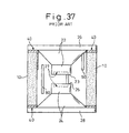
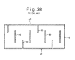
- this electrical discharge lamp is provided, in the traverse direction at the center of the inside wall of the airtight cylinder 10, with a plurality of main electrical discharge trigger wires 80 which are arranged at predetermined intervals, while the main electrical discharge trigger wires 80 rise in the vertical direction in parallel with the axis of the airtight cylinder 10.
- main electrical discharge trigger wires 80 On the upper inside wall of the airtight cylinder 10 between the main electrical discharge trigger wires 80, there are sub-electrical discharge trigger wires 90 which rise in the vertical direction in parallel with the axis of the airtight cylinder 10, and upper ends of these sub-electrical discharge trigger wires 90 are serially connected with the metalized face 40 formed on the upper end face of the airtight cylinder 10.
- sub-electrical discharge trigger wires 90 which rise in the vertical direction in parallel with the axis of the airtight cylinder 10, and the lower ends of these sub-electrical discharge trigger wires 90 are serially connected with the metalized face 40 formed on the lower end face of the airtight cylinder 10.
- this electrical discharge tube it is possible to prevent the electrical insulation between the main discharge trigger wires 80 and the sub-discharge trigger wires 90, which are arranged on the inner wall of the airtight cylinder 10, from being deteriorated by sputtering such as carbon particles which are created in the process of discharging from the electrical discharging face 23 at the forward end of the upper discharge electrode, the electrical discharging face 25 at the forward end of the lower discharge electrode, the main electrical discharge trigger wires 80 and the sub-electrical discharge trigger wires 90 and which adhere to the center of the inner wall of the airtight cylinder 10. Further, in this electrical discharge tube, it is possible to repeatedly and stably induce electrical discharges between the electrical discharging face 23 and the electrical discharging face 25 at a predetermined electrical potential over a long period of time.
- an electrical discharge gap is arranged at the side of the secondary coil opposite to the primary coil of the transformer.
- ballast circuits or igniter circuits including electrical resistors, coils, or the similar parts mounted at a high density, which are used for igniting the HID lamp or the like, as mentioned above.
- the electrical discharge tube constituting an electrical discharge gap is arranged close to the primary booster coil in the circuit, and the direction of the winding of the primary booster coil is substantially perpendicular to the direction of the main electrical discharge trigger wires 80 and the sub-electrical discharge trigger wires 90.
- the main electrical discharge trigger wires 80 and the sub-electrical discharge trigger wires 90 are affected by the magnetic field generated by the primary booster coil, and an electrical current is generated by the electromagnetic induction caused by the main electrical discharge trigger wires 80 and the sub-electrical discharge trigger wires 90. Being affected by the electrical current, the electrical potential of electrical discharges repeatedly induced between the electrical discharge face 23 and the electrical discharge face 25 cannot be stabilized, that is, the electrical potential of electrical discharges fluctuate and, further, the electrical discharge starting voltage initially generated between the electrical discharge face 23 and the electrical discharge face 25 is raised.
- the above ballast circuit used for igniting the HID lamp of a vehicle is embedded and fixed in resin such as urethane resin or epoxy resin so that the circuit can be protected from impact and vibration, and the electrical discharge tube composing the ballast circuit is surrounded by the dielectric resin.
- the electrical discharge tube is affected by the dielectric resin. Accordingly, it is impossible to effectively converge electrons of the corona discharge upon the sub-electrical discharge trigger wires 90 of the electrical discharge tube. Further, the electrical discharge starting voltage initially generated between the electrical discharge face 23 and the electrical discharge face 25 is raised.
- the present invention has been accomplished to solve the above problems. It is an object of the present invention to provide an electrical discharge tube which is not affected by the magnetic field generated by the primary booster coil in the ballast circuit or the igniter circuit and also which is not affected by the resin of the dielectric body surrounding the electrical discharge tube, so that electrical discharges at a predetermined electrical potential can be repeatedly induced and the electrical discharge starting voltage initially can be kept constant for a long time.
- a first electrical discharge tube which comprises: a cylindrical body, made of insulating material, having an inner surface and having upper and lower end faces defining respective upper and lower openings; upper and lower metallized layers formed on the respective upper and lower end faces of the cylindrical body, the upper and lower metallized layers being substantially parallel to each other; upper and lower electrodes for airtightly closing the respective upper and lower openings by means of the metallized layers, the upper and lower electrodes having respective electrical discharge faces between which an electrical discharge gap is defined; a first electrical discharge trigger wire formed as a loop on the inner surface of the cylindrical body and extending substantially parallel to the first and second metallized layers along a first surface located within a range of the electrical discharge gap; one or more second electrical discharge trigger wires formed on the inner surface of the cylindrical body and extending from the upper metallized layer to a fourth surface located between a second surface including the electrical discharge face of the upper electrode and the upper metallized layer; and one or more other second electrical discharge trigger wires formed on the inner surface
- a second electrical discharge tube which comprises: a cylindrical body, made of insulating material, having an inner surface, and having upper and lower end faces defining respective upper and lower openings; upper and lower metallized layers formed on the respective upper and lower end faces of the cylindrical body, the upper and lower metallized layers being substantially parallel to each other; upper, negative and lower, positive electrodes for airtightly closing the respective upper and lower openings by means of the metallized layers, the upper and lower electrodes having respective electrical discharge faces between which an electrical discharge gap is defined; a first electrical discharge trigger wire formed as a loop on the inner surface of the cylindrical body and extending substantially parallel to the first and second metallized layers along a first surface located within a range of the electrical discharge gap; and a plurality of electrical discharge trigger wires formed on the inner surface of the cylindrical body and extending from the upper metallized layer to a fourth surface located between a second surface including the electrical discharge face of the upper, negative electrode and the upper metallized layer.
- the first electrical discharge trigger wire arranged at the center of the inside wall of the airtight cylinder crosses the inside wall of the airtight cylinder substantially parallel with the metalized face and is formed into a loop-shape.
- the first discharge trigger wire is arranged in the traverse direction perpendicular to the axis of the airtight cylinder.
- the first electrical discharge trigger wire becomes substantially parallel with the direction of the winding of the primary booster coil in the above ballast circuit and others. Therefore, it is possible to prevent the generation of an electrical current in the first electrical discharge trigger wire by the electromagnetic induction being affected by the magnetic field of the primary booster coil.
- the second electrical discharge trigger wire is serially connected with the metalized face formed on the upper or the lower end face of the airtight cylinder. Therefore, this second electrical discharge trigger wire is electrically connected with the upper discharge electrode or the lower discharge electrode via the metalized face.
- the electrical discharge starting voltage generated at the first time by the second electrical discharge trigger wire can be stabilized without being raised.
- the first electrical discharge trigger wire is formed into a loop-shape in the traverse direction at the center of the inside wall of the airtight cylinder, as compared with the conventional electrical discharge tube in which a plurality of main electrical discharge trigger wires and sub-electrical discharge trigger wires are arranged in the traverse direction at predetermined intervals by being raised in the vertical direction of the inside wall of the airtight cylinder, it is possible to keep the distance between the first electrical discharge trigger wire and the second electrical discharge trigger wire arranged close to it on the inside wall of the airtight cylinder constant.
- the first electrical discharge trigger wire and the second electrical discharge trigger wire which are arranged at a constant distance, are used, electrical discharges at a predetermined electrical potential can be repeatedly and stably induced.
- the first electrical discharge trigger wire is formed into a loop-shape in the traverse direction at the center of the inside wall of the airtight cylinder. Therefore, as compared with the conventional electrical discharge tube in which the main electrical discharge trigger wires are divided into a plurality of pieces on the inside wall of the airtight cylinder and arranged in the traverse direction while they are directed vertically, the first electrical discharge trigger wire can be easily and quickly formed on the inside wall of the airtight cylinder.
- the inside wall portion of the airtight cylinder composed of insulating material, in which no trigger wires exist is widely arranged between the first electrical discharge trigger wire, which is formed at the center of the inside wall of the airtight cylinder, and the metalized face on the positive electrode side formed on the lower end face of the airtight cylinder.
- the aging treatment to activate the electrical discharge faces can be conducted only when a DC over-voltage is impressed between the negative electrode and the positive electrode only in one direction. Therefore, the process of the aging treatment, which is complicated, can be reduced by half.
- the aging treatment is defined as a treatment in which an over-voltage is repeatedly impressed between the upper discharge electrode and the lower discharge electrode in the case of manufacturing an electrical discharge tube, so that electrical discharges are repeatedly induced so as to activate the electrical discharge faces. After this aging treatment has been completed, electrical discharges can be smoothly and appropriately induced.
- one piece of the second electrical discharge trigger wire or a plurality of second electrical discharge trigger wires are arranged in the traverse direction on the upper inside wall and the lower inside wall of the airtight cylinder at predetermined intervals while being alternately shifted.
- the second electrical discharge trigger wires which are formed on the upper inside wall and the lower inside wall of the airtight cylinder while being adjacent to each other, are not arranged opposed to each other in the vertical direction but are arranged in the traverse direction at predetermined intervals. Therefore, it is possible to appropriately prevent the electrical insulation of the second electrical discharge trigger wires, which are formed on the upper inside wall and the lower inside wall of the airtight cylinder, from being deteriorated by the spatters adhering to the center of the inside wall of the airtight cylinder in the process of electrical discharge.
- the second electrical discharge trigger wires are composed of a plurality of the sub-second electrical discharge trigger wires which are arranged close to each other substantially in parallel with each other.
- the electrical discharge tube of the present invention when electrical discharges are repeatedly induced, it is possible to not raise the electrical discharge starting voltage at the first time, so that the electrical discharge starting voltage at the first time can be stabilized at a constant value over a long period of time.
- the above effect is remarkable especially when the electrical discharge tube is placed in a dark place and electrical discharges are repeatedly induced in a gas in which electrons in the space of the airtight cylinder of the electrical discharge tube are not excited.
- the electrical discharge starting voltage at the first time can be kept constant and the life of the electrical discharge tube can be greatly extended.
- the distance from the forward end of a single, second electrical discharge trigger wire, to the electrical discharge face of the upper discharge electrode or the electrical discharge face of the lower discharge electrode is gradually extended.
- the forward ends of the plurality of sub-second electrical discharge trigger wires of the second electrical discharge trigger wire which remains long, is not separated from the electrical discharge face of the forward end of the upper discharge electrode arranged close to it or the electrical discharge face of the forward end of the lower electrical discharge electrode.
- each of the plurality of the sub-second electrical discharge trigger wires composing the second electrical discharge trigger wires has the same function as that of the second electrical discharge trigger wire, the number of which is one. Therefore, when the plurality of the sub-second electrical discharge trigger wires, which are arranged too distant from each other, are used, the electrical discharge starting voltage of the electrical discharge tube at the first time is gradually raised at a dark place in its early stages.
- the second electrical discharge trigger wire is oblique with respect to the axis of the airtight cylinder.
- the second electrical discharge trigger wire is oblique with respect to the axis of the airtight cylinder. Further, the second electrical discharge trigger wire is obliquely directed in the upward and downward direction which is close to the direction of the windings of the primary booster coil of the ballast circuit and the igniter circuit.
- first or the second electrical discharge tubes of the present invention it is possible to adopt the following structure.
- a plurality of the first electrical discharge trigger wires are symmetrically arranged on both sides of the first plane in parallel with the metalized face while the plurality of the first electrical discharge trigger wires cross the inside wall of the airtight cylinder in a loop-shape being arranged in the vertical direction at predetermined intervals.
- a plurality of the first electrical discharge trigger wires are arranged in the traverse direction on the inside wall of the airtight cylinder so that the plurality of the first electrical discharge trigger wires can be substantially parallel with the direction of the windings of the primary booster coils of the ballast circuit and the igniter circuit. Therefore, it is possible to prevent an electrical current to be generated in the plurality of the first electrical discharge trigger wires by the electromagnetic induction being affected by the magnetic field of the primary booster coil. Further, it is possible to prevent the electrical discharge potential, which is repeatedly generated, and the electrical discharge starting voltage at the first time from fluctuating by being affected by the electrical current.
- the fist electrical discharge tube may have one or a plurality of interruptions in its intermediate portion.
- the electrons of the corona electrical discharge can be effectively converged so that electrical discharges can be induced.
- electrical discharges at a predetermined electrical potential can be repeatedly and stably induced.
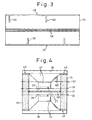
- reference numeral 10 is an airtight cylinder made of insulating material such as ceramics.
- the upper end opening and the lower end opening of the airtight cylinder 10 are respectively covered with the upper electrical discharge electrode 22 and the lower electrical discharge electrode 24 made of metal such as 42 alloy (iron-nickel alloy).
- the outside end portions of the upper electrical discharge electrode 22 and the lower electrical discharge electrode 24 are formed into disk-shaped covers 26, 28, and the upper end opening and the lower end opening of the airtight cylinder 10 are covered with the covers 26, 28.
- the upper electrical discharge electrode 22 and the lower electrical discharge electrode 24 are airtightly joined to the metalized faces 40 by means of soldering which are formed on the upper end face and the lower end face of the airtight cylinder 10 and made of metal such as chrome.
- soldering are formed on the upper end face and the lower end face of the airtight cylinder 10 and made of metal such as chrome.
- the inside space of the airtight cylinder 10, into which a mixed inert gas is charged, is airtightly sealed by the upper electrical discharge electrode 22 and the lower electrical discharge electrode 24.
- a forward end of the upper electrical discharge electrode 22 and a forward end of the lower electrical discharge electrode 24, which are housed inside the airtight cylinder 10, are respectively formed into a column-shape, the diameter of which is small.
- the forward end of the upper electrical discharge electrode 22 and the forward end of the lower electrical discharge electrode 24 are opposed to each other at the center of the airtight cylinder 10.
- a recess 27 is provided respectively on the electrical discharge face 23 at the forward end of the upper electrical discharge electrode and the electrical discharge face 25 at the forward end of the lower electrical discharge electrode, so that electrical discharges can be stably induced between the electrical discharge faces 23, 25.
- the above structure is the same as that of the conventional electrical discharge tube, the following structure of the first electrical discharge tube shown in the drawing is different from the structure of the conventional electrical discharge tube.
- the first electrical discharge tube shown in the drawing at the center of the inside wall of the airtight cylinder 10 located on the first plane (shown by one-dotted chain line in the drawing) which crosses the center of the electrical discharge gap between the electrical discharge face 23 and the electrical discharge face 25 opposed to each other at the center in the airtight cylinder 10, as shown in Fig.
- one piece of the first electrical discharge trigger wire 50 composed of a carbon wire, the width of which is about 0.5 mm, is arranged substantially in parallel with the metalized face 40 in a loop-shape in such a manner that the first electrical discharge trigger wire 50 crosses the inside wall of the airtight cylinder 10.
- one piece of, or a plurality of, the second electrical discharge trigger wires 60 which are composed of carbon wires, the wire width of which is about 0.5 mm, are arranged in such a manner that their forward end portions are located on the substantially same face as the fourth plane 37 which crosses the center between the second plane 33 including the electrical discharge face 23 and the metalized face 40 on the upper electrical discharge electrode 22 side while one piece or the plurality of the second electrical discharge trigger wires 60 are arranged in parallel with the axial direction of the airtight cylinder 10 in the traverse direction being raised.
- the rear end of one piece of the second electrical discharge trigger wire 60 or rear ends of a plurality pieces of the second electrical discharge trigger wires 60, which are formed on the upper inside wall of the airtight cylinder 10, are serially connected with the metalized face 40 formed on the upper end face of the airtight cylinder 10 close to it.
- one piece or a plurality of the second electrical discharge trigger wires 60 which are composed of carbon wires, the wire width of which is about 0.5 mm, are arranged in such a manner that their forward end portions are located on substantially the same face as the fifth plane 39 which crosses the center between the third plane 35 including the electrical discharge face 25 and the metalized face 40 on the lower electrical discharge electrode 24 side while one piece of or the plurality of the second electrical discharge trigger wires 60 are arranged in parallel with the axial direction of the airtight cylinder 10 in the traverse direction being raised.
- one piece or a plurality of pieces of the second electric discharge trigger wires 60 are arranged on the upper inside wall and the lower inside wall at predetermined intervals in the traverse direction being alternately shifted from each other.
- the second electrical discharge trigger wires 60 which are formed on the upper inside wall and the lower inside wall of the airtight cylinder 10 being adjacent to each other, are not arranged being opposed to each other in the vertical direction but are arranged in the traverse direction at predetermined intervals.
- the second electrical discharge trigger wires 60 which are formed on the upper inside wall and the lower inside wall of the airtight cylinder, from being caused by the spatters adhering to the center of the inside wall of the airtight cylinder 10 in the case of electrical discharge conducted by the electrical discharge face 23, the electrical discharge face 25, the first electrical discharge trigger wire 50 and the second electrical discharge trigger wire 60.
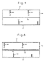
- a plurality of pieces of the first electrical discharge trigger wires 50 (two pieces of the first electrical discharge trigger wires 50 are shown in the drawing) made of carbon, the wire width of which is about 0.2 mm, are symmetrically arranged on both sides of the first plane 31 substantially in parallel with the metalized face 40 in a loop-shape at predetermined intervals in the vertical direction while the first electrical discharge trigger wires 50 cross the inside wall of the airtight cylinder 10.
- FIG. 6 Another preferable embodiment of the second electrical discharge tube is shown in Fig. 6 .
- a plurality of the first electrical discharge trigger wires 50 (the two electrical discharge trigger wires 50 are shown in the drawing) made of carbon, the wire width of which is 0.2 mm, are symmetrically arranged on both sides of the first plane 31 and cross the center of the electrical discharge gap formed between the electrical discharge face 23 and the electrical discharge face 25, in the traverse direction in a loop-shape at predetermined intervals while the plurality of the first electrical discharge trigger wires 50 cross the inside wall of the airtight cylinder 10 substantially parallel with the metalized face 40.
- the first electrical discharge trigger wire 50 of the electrical discharge tube is arranged in the traverse direction perpendicular to the axis of the airtight cylinder 10 and substantially parallel with the direction of the winding of the primary side booster coil in the ballast circuit into which this electrical discharge tube is incorporated. Therefore, it is possible to prevent the generation of an electrical current caused by the electromagnetic induction of the first electrical discharge trigger wire 50 being affected by the magnetic field of the primary side booster coil. As a result, it is possible to prevent the fluctuation of the electrical potential of electrical discharge repeatedly induced being affected by the magnetic field of the primary booster coil. Also, it is possible to keep the electrical discharge starting voltage at the first time constant.
- the second electrical discharge trigger wire 60 is composed in such a manner that the length of the second electrical discharge trigger wire 60 is short and substantially the same as the distance from the metalized face 40 to the fourth plane 37 or the fifth plane 39 located close to it. Therefore, electrons for the use of creeping corona discharge can be effectively converged upon the second electrical discharge trigger wires 60 without being affected by the resin. As a result, the electrical discharge starting voltage generated at the first time by the second electrical discharge trigger wire 60 can be stabilized without being raised.
- the forward end of the second electrical discharge trigger wire 60 is arranged substantially on the same face as the fourth plane 37 or the fifth plane 39, it is possible to prevent the forward end of the second electrical discharge trigger wire 60 from being located too distant from the electrical discharge face 23 or the electrical discharge face 25. Further, it is possible to prevent the electrical discharge starting voltage generated at the first time from being raised.
- first electrical discharge trigger wire 50 is formed into a loop-shape in the traverse direction at the center of the inside wall of the airtight cylinder 10, it is possible to keep constant the distance from the first electrical discharge trigger wire 50 to the second electrical discharge trigger wire 60, which is formed on the inside wall of the airtight cylinder 10 close to it.
- first electrical discharge trigger wire 50 and second electrical discharge trigger wire 60 which are separated by a constant distance, are used, electrical discharges of the electrical discharge tube induced at a predetermined electrical potential can be repeatedly and stably conducted.
- the first electrical discharge trigger wire 50 is serially formed into a loop-shape in the traverse direction at the center of the inside wall of the airtight cylinder 10. Therefore, the first electrical discharge trigger wire 50 can be easily and quickly formed without taking time and labor.
- the second electrical discharge trigger wires 60 which are formed on the upper inside wall and the lower inside wall of the airtight cylinder 10 and adjacent to each other, are arranged in the traverse direction at predetermined intervals. Accordingly, it is possible to prevent the occurrence of electrical shorts caused by spatters, which are created in the process of electrical discharge from the electrical discharge face 23, the electrical discharge face 25, the first trigger wire 50 and the second trigger wire 60, and which adhere to the center of the inside wall of the airtight cylinder 10, between the second electrical discharge trigger wires 60 disposed adjacent to each other.
- the inside wall portion of the airtight cylinder 10 composed of insulating material, in which no trigger wires exist, is widely arranged between the first electrical discharge trigger wire 50, which is formed at the center of the inside wall of the airtight cylinder 10, and the metalized face 40 on the positive electrode side formed on the lower end face of the airtight cylinder 10.
- the aging treatment to activate the electrical discharge faces 23, 25 can be conducted only when an over-voltage of DC is impressed between the upper electrical discharge electrode 22 on the negative electrode side and the lower electrical discharge electrode 24 on the positive electrode side only in one direction. Therefore, the process of the aging treatment, which is complicated, can be reduced by half.
- a plurality of pieces of the first electrical discharge trigger wires 50 are arranged at the center of the inside wall of the airtight cylinder 10 located between the second plane 33 and the third plane 35. Therefore, the plurality of pieces of the first electrical discharge trigger wires 50 are not protruded from the upper portion of the inside wall of the airtight cylinder 10 outside the second plane 33 and the lower portion of the inside wall of the airtight cylinder 10 outside the third plane 35 but formed at the center of the inside wall of the airtight cylinder 10 located inside it. Therefore, it is possible to prevent the plurality of pieces of the first electrical discharge trigger wires 50 from coming too close to the upper electrical discharge electrode 22 and the lower electrical discharge electrode 24. Accordingly, it is possible to prevent the electrical potential of electrical discharge from decreasing to lower than a predetermined value.
- the second electrical discharge trigger wires 60 are composed of a plurality of pieces of the second electrical discharge trigger wires 62 which are arranged close to each other substantially in parallel with each other.
- the electrical discharge starting voltage at the first time can be stabilized at a constant voltage, over a long period of time, without raising it.
- the above effect is remarkable especially when the electrical discharge tube is used for the ballast circuit and placed at a dark place surrounded by resin and electrical discharges are repeatedly induced in gas in which electrons in the space of the airtight cylinder 10 of the electrical discharge tube are not excited.
- the electrical discharge starting voltage at the first time can be kept constant and the life of the electrical discharge tube can be greatly extended, for the reason described before.
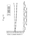
- Fig. 11 is a graph showing the result of a life test of the first electrical discharge tube conducted at a dark place, wherein the first electrical discharge tube is composed in such a manner that one piece of the first electrical discharge trigger wire 50 is provided at the center of the inside wall of the airtight cylinder 10, and the second electrical discharge trigger wires 60, in which two pieces of the sub-second electrical discharge trigger wires 62 are respectively arranged close to each other, and substantially parallel with each other, on the upper inside wall and the lower inside wall of the airtight cylinder 10, are shifted from each other one by one in the traverse direction by a distance corresponding to half of the circumferential length of the inside wall of the airtight cylinder 10.
- Fig. 12 is a graph showing the result of a life test of the first electrical discharge tube conducted at a dark place, wherein the first electrical discharge tube is composed in such a manner that one piece of the first electrical discharge trigger wire 50 is provided at the center of the inside wall of the airtight cylinder 10, and three pieces of the sub-second electrical discharge trigger wires 62 are respectively arranged close to each other substantially in parallel with each other on the upper inside wall and the lower inside wall, and the second electrical discharge trigger wires 60 are shifted from each other in the traverse direction by a distance corresponding to half of the circumferential length of the inside wall of the airtight cylinder 10.
- Fig. 13 is a graph showing the result of a life test of the first electrical discharge tube conducted at a dark place, wherein the first electrical discharge tube is composed in such a manner that one piece of the first electrical discharge trigger wire 50 is provided at the center of the inside wall of the airtight cylinder 10, and one piece of the sub-second electrical discharge trigger wire 60 is arranged on each of the upper inside wall and the lower inside wall, and the second electrical discharge trigger wire 60 is shifted from each other in the traverse direction by a distance corresponding to half of the circumferential length of the inside wall of the airtight cylinder 10.
- the second electrical discharge trigger wires 60 are composed of two pieces of the sub-second electrical discharge trigger wires 62, it is possible to stably and repeatedly induce electrical discharges of the electrical discharge operation voltage of 3,000 V about 900,000 times.
- the second electrical discharge trigger wires 60 are composed of three pieces trigger wires, it is possible to repeatedly and stably induce electrical discharges at the voltage of about 2,900 V not less than 1,000,000 times over a long period of time.
- the second electrical discharge trigger wires 60 are composed of one piece of trigger wire, it is only possible to induce electrical discharges, at the voltage of about 2,900 V, 200,000 times.
- Fig. 14 is a graph showing the result of a life test of the second electrical discharge tube conducted at a dark place, wherein the second electrical discharge tube is composed in such a manner that one piece of the first electrical discharge trigger wire 50 is provided at the center of the inside wall of the airtight cylinder 10, and two pieces of the second electrical discharge trigger wires 60, in which two pieces of the sub-second electrical discharge trigger wires 62 are respectively arranged close to each other and substantially in parallel with each other on the upper inside wall of the airtight cylinder 10, are shifted from each other in the traverse direction by a distance corresponding to half of the circumferential length of the inside wall of the airtight cylinder 10.
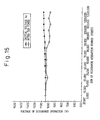
- Fig. 15 is a graph showing the result of a life test of the second electrical discharge tube conducted at a dark place, wherein the second electrical discharge tube is composed in such a manner that one piece of the first electrical discharge trigger wire 50 is provided at the center of the inside wall of the airtight cylinder 10, and two pieces of the second electrical discharge trigger wires 60, in which three pieces of the sub-second electrical discharge trigger wires 62 are respectively arranged close to each other and substantially in parallel with each other on the upper inside wall of the airtight cylinder 10, are shifted from each other in the traverse direction by a distance corresponding to half of the circumferential length of the inside wall of the airtight cylinder 10.
- Fig. 16 is a graph showing the result of a life test of the second electrical discharge tube conducted at a dark place, wherein the second electrical discharge tube is composed in such a manner that one piece of the first electrical discharge trigger wire 50 is provided at the center of the inside wall of the airtight cylinder 10, and two pieces of the second electrical discharge trigger wires 60, in which one piece of the sub-second electrical discharge trigger wire 60 is arranged on the upper inside wall of the airtight cylinder 10, are shifted from each other in the traverse direction by a distance corresponding to half of the circumferential length of the inside wall of the airtight cylinder 10.
- the second electrical discharge trigger wire 60 is composed of two pieces of the sub-second electrical discharge trigger wires 62, it is possible to repeatedly and stably induce electrical discharges, at a voltage of about 1,100 V, about 50,000 times.
- the second electrical discharge trigger wire 60 is composed of three pieces of the sub-second electrical discharge trigger wires 62, it is possible to repeatedly and stably induce electrical discharges, at the voltage of about 1,050 V, about 1,500,000 times.
- the second electrical discharge trigger wire 60 is composed of only one piece of the second sub-electrical discharge trigger wire 62, it is only possible to repeatedly induce electrical discharges, at the voltage of about 1,100 V, 20,000 times.
- the outer diameter of the airtight cylinder 10 was about 8 mm, and the gap in which the sub-electrical discharge trigger wire 62 is opposed to the side edge was 0.2 mm.
- the gap in which two or three pieces of the sub-electrical discharge trigger wires 62 composing the second electrical discharge trigger wire 60 were opposed to the side edge was preferably 0.1 to 0.25 mm.
- the function of the two or three pieces of the sub-electrical discharge trigger wires 62 becomes the same as the function of the second electrical discharge trigger wire 60 composed of one piece of the sub-electrical discharge trigger wire 62.
- the electrical discharge starting voltage at the first time of the electrical discharge tube at a dark place was gradually raised in its early stages.
- the function of the two or three pieces of the sub-second electrical discharge trigger wires 62 becomes the same as the function of the second electrical discharge trigger wire 60 composed of one piece of the sub-second electrical discharge trigger wire 62.
- the electrical discharge starting voltage at the first time of the electrical discharge tube at a dark place was gradually raised in its early stages.
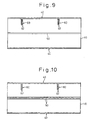
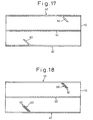
- one piece or a plurality of pieces of the second electrical discharge trigger wires 60 (in the case shown in the drawings, one piece of the second electrical discharge trigger wire 60 is shown) composed of a carbon wire, the width of which is about 0.5 mm, are arranged in such a manner that the second electrical discharge trigger wires 60 are inclined with respect to the axis of the airtight cylinder 10 in the same direction or alternately in the opposite direction being raised in the upward and downward direction.
- This second electrical discharge trigger wire 60 is composed of two pieces of the sub-electrical discharge trigger wires 62 or one piece of the second electrical discharge trigger wire 60.
- the forward end of the second electrical discharge trigger wire 60 is located substantially on the same plane as the fourth plane 37, and the backward end of the second electrical discharge trigger wire 60 is serially connected with the metalized face 40 formed on the upper end face of the airtight cylinder 10 located close to it.
- one piece of or a plurality of pieces of the second electrical discharge trigger wires 60 (in the case shown in the drawings, one piece of the second electrical discharge trigger wire 60 is shown) composed of a carbon wire, the width of which is about 0.5 mm, are arranged in such a manner that the second electrical discharge trigger wires 60 are inclined with respect to the axis of the airtight cylinder 10 in the same direction or alternately in the opposite direction being raised in the upward and downward direction.
- This second electrical discharge trigger wire 60 is composed of two pieces of the sub-electrical discharge trigger wires 62 or one piece of the second electrical discharge trigger wire 60.
- the forward end of the second electrical discharge trigger wire 60 is located substantially on the same plane as the fifth plane 39, and the backward end of the second electrical discharge trigger wire 60 is serially connected with the metalized face 40 formed on the lower end face of the airtight cylinder 10 located close to it.
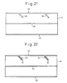
- not less than two pieces of the second electrical discharge trigger wires 60 (in the case shown in the drawings, two pieces of the second electrical discharge trigger wires 60 are shown) composed of a carbon wire, the width of which is about 0.5 mm, are arranged in such a manner that the second electrical discharge trigger wires 60 are inclined with respect to the axis of the airtight cylinder 10 in the same direction or alternately in the opposite direction by being raised in the upward and downward direction.
- This second electrical discharge trigger wire 60 is composed of two pieces of the sub-electrical discharge trigger wires 62 or one piece of the second electrical discharge trigger wire 60.
- the forward end of the second electrical discharge trigger wire 60 is located substantially on the same plane as the fourth plane 37, and the backward end of the second electrical discharge trigger wire 60 is serially connected with the metalized face 40 formed on the upper end face of the airtight cylinder 10 located close to it.
- the second electrical discharge trigger wire 60 is inclined with respect to the axis of the airtight cylinder 10, so that the second electrical discharge trigger wire 60 is formed in an oblique direction which is close to the direction of the winding of the primary booster coil of the ballast circuit or the igniter circuit. Therefore, it is possible to prevent an electrical current from being generated in a plurality of pieces of the second electrical discharge trigger wires 60 by the effect of electromagnetic induction being affected by the magnetic field of the primary side booster coil. Further, it is possible to prevent the electrical discharge starting voltage at the first time from being unstabilized being affected by the electrical current.
- the second electrical discharge trigger wire 60 is inclined with respect to the axis of the airtight cylinder 10 by not less than 45°. In this case, it is possible to appropriately prevent an electrical current, which is generated by the magnetic field of the primary side booster coil, from being generated in the second electrical discharge trigger wire 60. This was confirmed by an experiment made by the present inventors.
- the second electrical discharge trigger wire 60 is inclined with respect to the axis of the airtight cylinder 10, even if the electrical discharge tube is surrounded by a resin made of dielectric material, electrical discharges can be induced in the second electrical discharge trigger wire 60, so that electrons of the corona discharge can be effectively converged. Therefore, it is possible to prevent the electrical discharge starting voltage, at the first time, from being raised by using the second electrical discharge trigger wire 60.
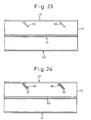
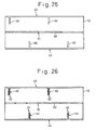
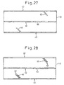
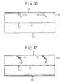
- one or a plurality of break portions 52 are formed in the middle portion of the first electrical discharge trigger wire 50, as shown in Figs. 25 to 32 .
- a total of the lengths of the break portions 52 of the first electrical discharge trigger wire 50 is smaller than the electrical discharge gap distance.
- Fig. 33 is the electrical discharge characteristic data of the conventional electrical discharge tube before it is incorporated into the ballast circuit.
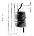
- Fig. 34 is the electrical discharge characteristic data of the conventional electrical discharge tube which is incorporated close to the primary side booster coil in the ballast circuit and embedded in resin.
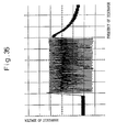
- Fig. 35 is the electrical discharge characteristic data of the first electrical discharge tube before it is incorporated into the ballast circuit.
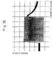
- Fig. 36 is the electrical discharge characteristic data of the first electrical discharge tube which is incorporated close to the primary side booster coil in the ballast circuit and embedded in the resin.
- the vertical axis represents the electrical discharge voltage
- the unit scale represents 1000 V.
- the horizontal axis represents the electrical discharge frequency, and the unit scale represents 200 msec.
- the first electrical discharge tube shown in Figs. 1 and 2 is advantageous in that even if the first electrical discharge tube is incorporated into a portion close to the primary side booster coil in the ballast circuit and embedded in a resin, the first electrical discharge tube is not affected by the primary side booster coil and the resin, so that electrical discharges at a predetermined voltage can be stably and repeatedly induced and the electrical discharge starting voltage at the first time can be kept constant without being raised.
Landscapes
- Testing Relating To Insulation (AREA)
- Discharge Lamps And Accessories Thereof (AREA)
- Lasers (AREA)
- Ignition Installations For Internal Combustion Engines (AREA)
Claims (10)
- Elektrische Entladungsröhre, mit:• einem zylindrischen Körper (10) aus Isoliermaterial, der eine Innenfläche aufweist und der obere und untere Endseiten aufweist, die jeweilige obere und untere Öffnungen definieren;• oberen und unteren metallisierten Schichten (40), die an den jeweiligen oberen und unteren Endseiten des zylindrischen Körpers gebildet sind, wobei die oberen und unteren metallisierten Schichten (40) im Wesentlichen parallel zueinander verlaufen;• oberen und unteren Elektroden (26, 28) zum luftdichten Verschließen der jeweiligen oberen und unteren Öffnungen durch die metallisierten Schichten (40), wobei die oberen und unteren Elektroden (26, 28) jeweilige elektrische Entladungsseiten (23, 25) aufweisen, zwischen denen ein elektrischer Entladungsspalt definiert ist;• einem ersten Zünddraht (50) für elektrische Entladung, der an der Innenfläche des zylindrischen Körpers (10) als eine Schlaufe ausgebildet ist und im Wesentlichen parallel zur ersten und zweiten metallisierten Schicht (40) entlang einer ersten Fläche (31) verläuft, die innerhalb eines Bereichs des elektrischen Entladungsspalts angeordnet ist; und• einem oder mehreren zweiten Zünddrähten (60) für elektrische Entladung, die an der Innenfläche des zylindrischen Körpers (10) ausgebildet sind und von der oberen metallisierten Schicht (40) zu einer vierten Fläche (37) verlaufen, die zwischen einer zweiten Fläche (33), die die elektrische Entladungsseite der oberen Elektrode (26) enthält, und der oberen metallisierten Schicht (40) angeordnet ist.
- Elektrische Entladungsröhre nach Anspruch 1, wobei die erste Fläche (31) durch eine Zwischenstellung im elektrischen Entladungsspalt läuft und wobei die vierte Fläche (37) durch eine Zwischenstellung zwischen der zweiten Fläche (33) und der oberen metallisierten Schicht (40) läuft.
- Elektrische Entladungsröhre nach Anspruch 1 oder 2, die ferner eine oder mehrere weitere zweite Zünddrähte (60) für elektrische Entladung enthält, die auf der Innenfläche des zylindrischen Körpers (10) ausgebildet sind und von der unteren metallisierten Schicht (40) zu einer fünften Fläche (39) verlaufen, die zwischen einer dritten Fläche (35), die die elektrische Entladungsseite der unteren Elektrode enthält, und der unteren metallisierten Schicht (40) angeordnet sind.
- Elektrische Entladungsröhre nach Anspruch 3, wobei die fünfte Fläche (39) durch eine Zwischenstellung zwischen der dritten Fläche (35) und der unteren metallisierten Schicht (40) läuft.
- Elektrische Entladungsröhre nach Anspruch 3 oder 4, wobei der eine oder die mehreren zweiten Zünddrähte (60) für elektrische Entladung, die von der oberen metallisierten Schicht (40) verlaufen, und der eine oder die mehreren zweiten Zünddrähte (60) für elektrische Entladung, die von der unteren metallisierten Schicht (40) verlaufen, einander gegenüber in einer Umfangsrichtung versetzt angeordnet sind.
- Elektrische Entladungsröhre nach jedem der vorhergehenden Ansprüche, wobei der erste Zünddraht (50) für elektrische Entladung kontinuierlich in einer Umfangsrichtung ausgebildet ist.
- Elektrische Entladungsröhre nach jedem der Ansprüche 1 bis 5, wobei der erste Zünddraht (50) für elektrische Entladung wenigstens einen diskontinuierlichen Bereich (52) aufweist.
- Elektrische Entladungsröhre nach jedem der vorhergehenden Ansprüche, wobei der erste Zünddraht für elektrische Entladung wenigstens zwei erste Teilzünddrähte (50) aufweist, die parallel und nebeneinander angeordnet sind.
- Elektrische Entladungsröhre nach jedem der vorhergehenden Ansprüche, wobei der bzw. jeder zweite Zünddraht für elektrische Entladung gerade und parallel zu einer Achse des zylindrischen Körpers (10) verläuft oder gerade und geneigt in einem Winkel bezüglich einer Achse des zylindrischen Körpers (10) verläuft.
- Elektrische Entladungsröhre nach jedem der vorhergehenden Ansprüche, wobei der bzw. jeder zweite Zünddraht (60) für elektrische Entladung wenigstens zwei zweite Teilzünddrähte (62) aufweist, die parallel und nebeneinander angeordnet sind.
Applications Claiming Priority (4)
| Application Number | Priority Date | Filing Date | Title |
|---|---|---|---|
| JP20318499 | 1999-07-16 | ||
| JP20318499 | 1999-07-16 | ||
| JP2000110213 | 2000-04-12 | ||
| JP2000110213A JP2001093644A (ja) | 1999-07-16 | 2000-04-12 | 放電管 |
Publications (3)
| Publication Number | Publication Date |
|---|---|
| EP1069589A2 EP1069589A2 (de) | 2001-01-17 |
| EP1069589A3 EP1069589A3 (de) | 2002-07-31 |
| EP1069589B1 true EP1069589B1 (de) | 2008-03-26 |
Family
ID=26513784
Family Applications (1)
| Application Number | Title | Priority Date | Filing Date |
|---|---|---|---|
| EP00305943A Expired - Lifetime EP1069589B1 (de) | 1999-07-16 | 2000-07-13 | Elektrische Entladungsröhre |
Country Status (5)
| Country | Link |
|---|---|
| US (1) | US6313581B1 (de) |
| EP (1) | EP1069589B1 (de) |
| JP (1) | JP2001093644A (de) |
| KR (1) | KR100813932B1 (de) |
| DE (1) | DE60038416T2 (de) |
Families Citing this family (4)
| Publication number | Priority date | Publication date | Assignee | Title |
|---|---|---|---|---|
| JP2002270329A (ja) * | 2001-03-09 | 2002-09-20 | Shinko Electric Ind Co Ltd | ガス封入スイッチング放電管 |
| JP2004220808A (ja) | 2003-01-09 | 2004-08-05 | Shinko Electric Ind Co Ltd | 放電管及びその配設構造 |
| JP4410527B2 (ja) * | 2003-10-06 | 2010-02-03 | 新光電気工業株式会社 | 放電管 |
| DE112006002464T5 (de) | 2005-09-14 | 2008-07-24 | Littelfuse, Inc., Des Plaines | Gasgefüllter Überspannungsableiter, aktivierende Verbindung, Zündstreifen und Herstellungsverfahren dafür |
Family Cites Families (8)
| Publication number | Priority date | Publication date | Assignee | Title |
|---|---|---|---|---|
| CH600630A5 (de) * | 1977-01-27 | 1978-06-30 | Cerberus Ag | |
| JPS607183U (ja) * | 1983-06-25 | 1985-01-18 | 株式会社サンコ−シャ | 過電圧保護素子 |
| JPS6055091U (ja) * | 1983-09-22 | 1985-04-17 | 株式会社サンコ−シャ | 放電形避雷器 |
| US4680665A (en) | 1985-12-03 | 1987-07-14 | Reliance Comm/Tec Corporation | Gas discharge arrester |
| DE4318994C2 (de) * | 1993-05-26 | 1995-04-20 | Siemens Ag | Gasgefüllter Überspannungsableiter |
| US5739637A (en) * | 1995-09-28 | 1998-04-14 | Sandia Corporation | Cold cathode vacuum discharge tube |
| CH691245A5 (de) * | 1996-01-12 | 2001-05-31 | Epcos Ag | Gasgefüllte Entladungsstrecke. |
| JPH10335042A (ja) * | 1997-03-31 | 1998-12-18 | Shinko Electric Ind Co Ltd | 放電管 |
-
2000
- 2000-04-12 JP JP2000110213A patent/JP2001093644A/ja active Pending
- 2000-07-12 US US09/614,747 patent/US6313581B1/en not_active Expired - Lifetime
- 2000-07-13 EP EP00305943A patent/EP1069589B1/de not_active Expired - Lifetime
- 2000-07-13 DE DE60038416T patent/DE60038416T2/de not_active Expired - Lifetime
- 2000-07-14 KR KR1020000040582A patent/KR100813932B1/ko not_active Expired - Fee Related
Also Published As
| Publication number | Publication date |
|---|---|
| EP1069589A3 (de) | 2002-07-31 |
| DE60038416D1 (de) | 2008-05-08 |
| US6313581B1 (en) | 2001-11-06 |
| KR100813932B1 (ko) | 2008-03-14 |
| DE60038416T2 (de) | 2009-04-30 |
| EP1069589A2 (de) | 2001-01-17 |
| JP2001093644A (ja) | 2001-04-06 |
| KR20010029945A (ko) | 2001-04-16 |
Similar Documents
| Publication | Publication Date | Title |
|---|---|---|
| US8278807B2 (en) | Radiofrequency plasma generation device | |
| EP0585108B1 (de) | Fluoreszenz Lampe | |
| GB2170038A (en) | Gas laser | |
| US4253047A (en) | Starting electrodes for solenoidal electric field discharge lamps | |
| WO2000058998A1 (en) | Lighting arrangement | |
| KR100467877B1 (ko) | 유전성 임피디드 방전을 포함하는 방전 램프용 전자식 안정기 | |
| US20040232847A1 (en) | Electromagnetic pulse device | |
| EP1069589B1 (de) | Elektrische Entladungsröhre | |
| US7915828B2 (en) | High-voltage pulse generator, and lighting apparatus and vehicle having the same | |
| KR20010062136A (ko) | 자외선을 방출하는 가스 레이저 장치 | |
| US7842907B2 (en) | Microwave generator | |
| US4959592A (en) | Starting electrodes for HID lamps | |
| EP0869529B1 (de) | Entladungsröhre | |
| US7218051B2 (en) | Discharge tube | |
| JP3995339B2 (ja) | 放電管 | |
| JPH0260048A (ja) | 高光度放電ランプ用始動電極 | |
| US6297583B1 (en) | Gas discharge lamp assembly with improved r.f. shielding | |
| JPS5811065B2 (ja) | 交叉磁場使用のスイッチ装置 | |
| US4035683A (en) | High voltage electric switch with trigger electrodes integral with main discharge electrodes | |
| EP1443539B1 (de) | Entladungsröhre | |
| JP3627909B2 (ja) | 放電管 | |
| US7102289B2 (en) | Discharge tube | |
| JPH0697628B2 (ja) | シリーズギャップ付点火装置 | |
| US5032423A (en) | Method of forming conductor pattern on dielectric | |
| CA2000523A1 (en) | Starting electrodes for hid lamps |
Legal Events
| Date | Code | Title | Description |
|---|---|---|---|
| PUAI | Public reference made under article 153(3) epc to a published international application that has entered the european phase |
Free format text: ORIGINAL CODE: 0009012 |
|
| AK | Designated contracting states |
Kind code of ref document: A2 Designated state(s): AT BE CH CY DE DK ES FI FR GB GR IE IT LI LU MC NL PT SE |
|
| AX | Request for extension of the european patent |
Free format text: AL;LT;LV;MK;RO;SI |
|
| PUAL | Search report despatched |
Free format text: ORIGINAL CODE: 0009013 |
|
| AK | Designated contracting states |
Kind code of ref document: A3 Designated state(s): AT BE CH CY DE DK ES FI FR GB GR IE IT LI LU MC NL PT SE |
|
| AX | Request for extension of the european patent |
Free format text: AL;LT;LV;MK;RO;SI |
|
| RIC1 | Information provided on ipc code assigned before grant |
Free format text: 7H 01T 1/22 A |
|
| 17P | Request for examination filed |
Effective date: 20020801 |
|
| AKX | Designation fees paid |
Designated state(s): DE FR GB |
|
| GRAP | Despatch of communication of intention to grant a patent |
Free format text: ORIGINAL CODE: EPIDOSNIGR1 |
|
| GRAS | Grant fee paid |
Free format text: ORIGINAL CODE: EPIDOSNIGR3 |
|
| GRAA | (expected) grant |
Free format text: ORIGINAL CODE: 0009210 |
|
| AK | Designated contracting states |
Kind code of ref document: B1 Designated state(s): DE FR GB |
|
| REG | Reference to a national code |
Ref country code: GB Ref legal event code: FG4D |
|
| REF | Corresponds to: |
Ref document number: 60038416 Country of ref document: DE Date of ref document: 20080508 Kind code of ref document: P |
|
| ET | Fr: translation filed | ||
| PLBE | No opposition filed within time limit |
Free format text: ORIGINAL CODE: 0009261 |
|
| STAA | Information on the status of an ep patent application or granted ep patent |
Free format text: STATUS: NO OPPOSITION FILED WITHIN TIME LIMIT |
|
| 26N | No opposition filed |
Effective date: 20081230 |
|
| REG | Reference to a national code |
Ref country code: FR Ref legal event code: PLFP Year of fee payment: 17 |
|
| PGFP | Annual fee paid to national office [announced via postgrant information from national office to epo] |
Ref country code: FR Payment date: 20160613 Year of fee payment: 17 |
|
| PGFP | Annual fee paid to national office [announced via postgrant information from national office to epo] |
Ref country code: DE Payment date: 20160705 Year of fee payment: 17 Ref country code: GB Payment date: 20160713 Year of fee payment: 17 |
|
| REG | Reference to a national code |
Ref country code: DE Ref legal event code: R119 Ref document number: 60038416 Country of ref document: DE |
|
| GBPC | Gb: european patent ceased through non-payment of renewal fee |
Effective date: 20170713 |
|
| REG | Reference to a national code |
Ref country code: FR Ref legal event code: ST Effective date: 20180330 |
|
| PG25 | Lapsed in a contracting state [announced via postgrant information from national office to epo] |
Ref country code: GB Free format text: LAPSE BECAUSE OF NON-PAYMENT OF DUE FEES Effective date: 20170713 Ref country code: DE Free format text: LAPSE BECAUSE OF NON-PAYMENT OF DUE FEES Effective date: 20180201 |
|
| PG25 | Lapsed in a contracting state [announced via postgrant information from national office to epo] |
Ref country code: FR Free format text: LAPSE BECAUSE OF NON-PAYMENT OF DUE FEES Effective date: 20170731 |