EP1069442B1 - Systèmes de prismes pour inversion d'image dans un trajet d'observation visuel - Google Patents
Systèmes de prismes pour inversion d'image dans un trajet d'observation visuel Download PDFInfo
- Publication number
- EP1069442B1 EP1069442B1 EP00112829A EP00112829A EP1069442B1 EP 1069442 B1 EP1069442 B1 EP 1069442B1 EP 00112829 A EP00112829 A EP 00112829A EP 00112829 A EP00112829 A EP 00112829A EP 1069442 B1 EP1069442 B1 EP 1069442B1
- Authority
- EP
- European Patent Office
- Prior art keywords
- prism
- face
- gable
- bottom face
- roof
- Prior art date
- Legal status (The legal status is an assumption and is not a legal conclusion. Google has not performed a legal analysis and makes no representation as to the accuracy of the status listed.)
- Expired - Lifetime
Links
- 230000000007 visual effect Effects 0.000 title description 2
- 238000005259 measurement Methods 0.000 claims description 9
- 230000005540 biological transmission Effects 0.000 claims description 8
- 230000003595 spectral effect Effects 0.000 claims description 8
- 230000007935 neutral effect Effects 0.000 claims description 5
- 239000011248 coating agent Substances 0.000 claims description 4
- 238000000576 coating method Methods 0.000 claims description 4
- 238000003384 imaging method Methods 0.000 abstract description 5
- 239000011521 glass Substances 0.000 description 6
- 230000005855 radiation Effects 0.000 description 6
- 210000001747 pupil Anatomy 0.000 description 5
- 230000003287 optical effect Effects 0.000 description 4
- 230000008878 coupling Effects 0.000 description 3
- 238000010168 coupling process Methods 0.000 description 3
- 238000005859 coupling reaction Methods 0.000 description 3
- 238000003780 insertion Methods 0.000 description 3
- 230000037431 insertion Effects 0.000 description 3
- 230000007423 decrease Effects 0.000 description 2
- 230000004075 alteration Effects 0.000 description 1
- 201000009310 astigmatism Diseases 0.000 description 1
- 230000033228 biological regulation Effects 0.000 description 1
- 239000004568 cement Substances 0.000 description 1
- 238000006073 displacement reaction Methods 0.000 description 1
- 230000000694 effects Effects 0.000 description 1
- 238000005562 fading Methods 0.000 description 1
- 230000002349 favourable effect Effects 0.000 description 1
- 230000001678 irradiating effect Effects 0.000 description 1
- 230000000873 masking effect Effects 0.000 description 1
- 238000012634 optical imaging Methods 0.000 description 1
- 238000005457 optimization Methods 0.000 description 1
- 229910000679 solder Inorganic materials 0.000 description 1
- 238000001429 visible spectrum Methods 0.000 description 1
Images


Classifications
-
- G—PHYSICS
- G02—OPTICS
- G02B—OPTICAL ELEMENTS, SYSTEMS OR APPARATUS
- G02B23/00—Telescopes, e.g. binoculars; Periscopes; Instruments for viewing the inside of hollow bodies; Viewfinders; Optical aiming or sighting devices
- G02B23/02—Telescopes, e.g. binoculars; Periscopes; Instruments for viewing the inside of hollow bodies; Viewfinders; Optical aiming or sighting devices involving prisms or mirrors
- G02B23/10—Telescopes, e.g. binoculars; Periscopes; Instruments for viewing the inside of hollow bodies; Viewfinders; Optical aiming or sighting devices involving prisms or mirrors reflecting into the field of view additional indications, e.g. from collimator
Definitions
- the invention relates to a prism system for image reversal in a visual observation beam path, which consists of a roof prism with roof surface inclined to the base surface and an inclined to the base surface gable surface to which a reflection prism is added, said reflection prism has a parallel to the base surface of the roof prism beam passing surface.
- Such a prism system is known from DE-PS 518 143 and is referred to there as a parallel reversing prism system. It has only two airborne, parallel beam passing surfaces and six mirror surfaces which are arranged so that all reflections occur in one plane and are all totally reflecting. The picture rays enter the base area of the roof prism. The angle between the base surface of the roof prism and the cemented next reflection surface should be less than 110 °.
- Such prism systems are commonly used in afocal optical imaging systems, e.g. used in telescopes.
- the additional functions such as laser distance measurement or inclination and direction measurement (compass) have.
- the measurement results are preferably displayed so that they can be read when looking into the eyepiece.
- This variant is to be preferred as the ergonomically favorable, since the fade in at the edge of the field when reading to a Twisting the eye leads, in which the pupil of the eye initially moved out of the exit pupil of the binoculars, since the eye pivot is typically more than an inch behind the pupil. By parallel displacement of the binoculars, therefore, the exit pupil must each be newly searched.
- a beam splitter for image superimposition offers the additional possibility of sharing the observation beam path for transmitting or receiving the laser radiation, for example when used as combined binoculars with a laser distance meter.
- dichroic splitters are particularly suitable for the beam splitters since the display wavelength of a display usually emits at the red edge of the visible spectrum, but a possible diode laser preferably emits in the near infrared.
- the reflection surface is not only stressed at an angle of 45 °, but due to the finite aperture and the extended image field, for example at an angle of 45 ⁇ 5 °. this leads to especially with dichroic beam splitters to a color cast course over both the field of view and the pupil.
- the reflection of the beam splitter at the edge of the angular range due to the Brewster effect, especially for higher-refractive glasses such as BaK4, which are now used for reverse prisms in binoculars mainly decreases sharply, resulting in a decrease in brightness.
- a Porro prism system of the first type is known, to which a further prism for masking an image recording beam path from the observation beam path, or for glaring an image reproduction beam path is cemented into the observation beam path.
- the cement surface serving to reflect the observation beam path and to emit or fade in the further beam paths is designed as a beam splitter.
- the observation beam path is straight with an axis offset.
- a roof prism is known, on whose gable surface a rectangular prism is cemented with its Hypothenusenthesis.
- One of the catheter surfaces is aligned parallel to the base surface of the roof prism.
- the cemented surface is designed as a beam splitter.
- the observation beam entering the roof prism is reflected parallel to the base surface at the edge of the roof and, after reflection on the gable surface, emerges parallel and opposite to the entering observation beam path from the base surface.
- About the surface parallel to the base surface of the cemented prism can be superimposed on the emerging observation beam path, a further beam path.
- the invention therefore an object of the invention to provide a possibility of reflection of additional beam paths in the observation beam path in a straight prism system, which does not affect the imaging quality of the observation beam path and can be realized with low component complexity.
- the gable surface (10) is assigned a beam-dividing coating (10 ').
- the sloping gable surface of the roof prism should form an angle of 22.5 to 30 ° with the base surface.
- a reflection prism a rectangular prism is preferably selected.
- the reflective surfaces forming a right angle may face the gable surface.
- Observation beam is suitably chosen the beam passing surface of the reflection prism.
- An essential step in the solution of the problem underlying the invention consists in the selection of the constructed only of two glass parts reversing system, which leads to a significant cost savings. Another key feature is that the reflection on the inverting system could be maintained, eliminating the need for a separate beam splitter element. For the reflection, however, now an area is used, which is claimed by the actual telescope beam path in transmission and not in reflection.
- the selected inclination of the gable surface of the roof prism results in a much steeper angle of incidence at which this surface is penetrated by the beam path, namely typically in a range of 60 to 67.5 ° (corresponding to 22.5 to 30 ° to the solder on this surface).
- dichroic beam splitters with significantly lower color cast and uniformly high transmission in an angular range of ⁇ 5 °.
- a dichroic beam splitter e.g. metallic neutral divider can be used. Since the beam splitter ratio is chosen in favor of the binocular image in most applications, inevitably results in a little absorbing splitter layer, at the same time the remaining reflection still sufficient for a suitable reflection of the measured value display and eye-safe coupling of the laser radiation.
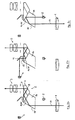
- Fig. 1a shows an afocal optical system which, in addition to a telescope with reiv1, prism system 2 and eyepiece 3 a deliberatelyaptnde display 4, and a light source 5 irradiating the observed object, e.g. a Laserdieode, as a transmitting element of a distance meter contains.
- the core element is the prism system 2, which consists of a roof prism 6 and a reflection prism 7.
- the roof edge 8 of the roof prism 6 is inclined relative to the base surface 9.
- the gable surface 10 is inclined.
- the reflection prism 7 is attached to the gable surface 10 with its reflecting surfaces 7 ', 7 "lying opposite one another at right angles to the gable surface 10.
- a beam-dividing coating 10' is applied to the gable surface 10.
- the two prisms are preferably cemented together
- Beam splitter 10 'and optical axis 11 is here 60 ° and is chosen so that the beam entrance of the observation beam path perpendicular to the glass / air surface 7' takes place on the reflection prism 7.
- the beam splitter 10 ' is used in transmission small axial offset between the beam path entering the prism system and the beam path exiting the eyepiece 3.
- Fig. 1 b shows the reflection of the display 4 in the optical path leading to the eyepiece 3.
- the imaging beams are also introduced perpendicular to the glass / air surface 9 of the roof prism 6 in the roof prism 6.
- the imaging beams are superimposed on the observation beam path. The reflection takes place at the same base surface 9 as for the exit of the observation beams to the eyepiece 3, but in one of them geometrically separate area.
- Fig. 1 c shows the coupling of the light source 5 in the lens-side beam path.
- the beam entry also takes place perpendicular to the glass / air surface 7 'on the reflection prism 7, again in a region which is geometrically separated from the entrance region of the observation beams.
- the beam splitter 10 also works here in reflection. Does it come to the Coupling efficiency of the light source, one will select high the reflection for the relevant (usually in the near infrared) wavelength, which generally leads to dichroic dividers.
- the embodiment shown in Fig. 2a to c differs from the embodiment shown in Figure 1 only in the design of the reflection prism 14, which is adjacent to the gable surface 10 in the region of the base surface 9 first reflection surface 14 'for the incoming observation beams perpendicular to the gable surface 10 stands. Although this results in a larger axial offset between the lens side and eyepiece beam paths, but for the number of deflections in the prism system is lower.
- the choice between the two embodiments will be based on the space available in the far-optical device to be set up.
- Fig. 3 shows a variant of the embodiment shown in Fig. 2, for which also the available space conditions are crucial.
- the display 4 is coupled via a made in front of the light source 5 divider mirror 15 in the laser beam path.
- the splitter mirror passes the laser wavelength, but reflects the display wavelength.
- the display wavelength is partially transmitted and directed via an additional concave mirror 16 again on the beam splitter 10 ⁇ and this time superimposed on the exiting observation beam path after partial reflection.
- a recording beam path is shown for the measuring radiation reflected by the observed object, from which a distance measuring signal is obtained and displayed on the display 4.
- the Recording beam path consists of an objective 17 and a receiving diode 18 and is aligned generally parallel to the observation beam path.
- a separate transmission beam path can also be provided.
- the light source 5 and the display 4 can be introduced without detour via the splitter mirror 15 in the prism system and further in the observation beam path.
Landscapes
- Physics & Mathematics (AREA)
- Astronomy & Astrophysics (AREA)
- General Physics & Mathematics (AREA)
- Optics & Photonics (AREA)
- Optical Elements Other Than Lenses (AREA)
- Telescopes (AREA)
- Investigating Or Analysing Materials By Optical Means (AREA)
- Instruments For Viewing The Inside Of Hollow Bodies (AREA)
- Microscoopes, Condenser (AREA)
Claims (9)
- Système de prismes (2) à vision directe pour inversion d'image qui se compose d'un prisme triangulaire (6) dont l'arête supérieure (8) est inclinée par rapport à la surface de base (9) et d'une surface frontale (10) en biais par rapport à la surface de base (9), l'inclinaison de l'arête supérieure (8) étant choisie de telle sorte qu'un rayon qui pénètre perpendiculairement à travers la surface de base (9) est reflétée de l'arête supérieure (8) sur la surface de base (9), et un prisme à réflexion (7 ; 14) étant accolé à la surface frontale (10), ce prisme à réflexion (7 ; 14) présentant au moins une surface de réflexion (7'' ; 14') pour le rayon réfléchi sur la surface de base (9) et qui traverse la surface frontale (10) ainsi qu'une surface (7') parallèle à la surface de base (9) destinée à être traversée perpendiculairement par le rayon, caractérisé en ce que- l'inclinaison de la surface frontale (10) par rapport à la surface de base (9) est choisie de telle sorte que le premier rayon qui est réfléchi sur la surface de base (9) est incident sur la surface frontale (10) sous un angle compris dans la plage de 60° à 67,5°,- un revêtement séparateur de rayons (10') est associé à la surface frontale (10),- la surface de base (9) du prisme triangulaire (6) et la surface (7') du prisme à réflexion (7 ; 14) qui lui est parallèle présentent respectivement une deuxième zone de traversée de rayon séparée géométriquement de la zone de traversée de rayon du premier rayon pour la traversée perpendiculaire d'un deuxième et/ou troisième rayon, et- les deuxièmes zones de traversée de rayon de la surface de base (9) du prisme triangulaire (6) et la surface (7') du prisme à réflexion (7 ; 14) qui est parallèle à la surface de base sont à l'opposé de la surface frontale (10) de telle sorte que les deuxièmes et/ou les troisièmes rayons peuvent être superposés au premier rayon au niveau de la surface frontale.
- Système de prismes selon la revendication 1, caractérisé en ce que le séparateur de rayons (10') est transmetteur pour la plage spectrale des rayons d'observation et réfléchissant pour la plage spectrale de l'indicateur de valeur mesurée et de la mesure de distance.
- Système de prismes selon la revendication 1, caractérisé en ce que le séparateur de rayons (10') est réalisé sous la forme d'un séparateur neutre diélectrique ou métallique avec une réflexion comprise entre 10 et 40 %.
- Système de prismes selon la revendication 1, caractérisé en ce que le séparateur de rayons (10') est réalisé sous la forme d'un séparateur dichroïque avec une bonne transmission dans la plage spectrale visible et une bonne réflexion dans la plage spectrale des infrarouges.
- Système de prismes selon la revendication 1, caractérisé en ce que la surface frontale (10) en biais du prisme triangulaire (6) forme un angle de 22,5 à 30° avec la surface de base (9).
- Système de prismes selon la revendication 1, caractérisé en ce que le prisme à réflexion (7) est un prisme rectangulaire.
- Système de prismes selon la revendication 6, caractérisé en ce que les surfaces de réflexion du prisme rectangulaire qui forment ensemble un angle droit sont à l'opposé de la surface frontale (10).
- Système de prismes selon la revendication 6, caractérisé en ce que l'une des surfaces de réflexion du prisme rectangulaire forme un angle droit avec la zone de la surface frontale (10) dirigée vers la surface de base (9) du prisme triangulaire (6).
- Système de prismes selon la revendication 1, caractérisé en ce que la surface de traversée du rayon du prisme à réflexion (7) forme le côté entrée du trajet de rayon d'observation.
Applications Claiming Priority (2)
| Application Number | Priority Date | Filing Date | Title |
|---|---|---|---|
| DE19933172 | 1999-07-15 | ||
| DE19933172A DE19933172C1 (de) | 1999-07-15 | 1999-07-15 | Prismensystem zur Bildumkehr in einem visuellen Beobachtungsstrahlengang |
Publications (3)
| Publication Number | Publication Date |
|---|---|
| EP1069442A2 EP1069442A2 (fr) | 2001-01-17 |
| EP1069442A3 EP1069442A3 (fr) | 2003-08-27 |
| EP1069442B1 true EP1069442B1 (fr) | 2006-01-18 |
Family
ID=7914890
Family Applications (1)
| Application Number | Title | Priority Date | Filing Date |
|---|---|---|---|
| EP00112829A Expired - Lifetime EP1069442B1 (fr) | 1999-07-15 | 2000-06-17 | Systèmes de prismes pour inversion d'image dans un trajet d'observation visuel |
Country Status (4)
| Country | Link |
|---|---|
| US (1) | US6292314B1 (fr) |
| EP (1) | EP1069442B1 (fr) |
| AT (1) | ATE316250T1 (fr) |
| DE (2) | DE19933172C1 (fr) |
Families Citing this family (26)
| Publication number | Priority date | Publication date | Assignee | Title |
|---|---|---|---|---|
| ATE356366T1 (de) | 2003-12-12 | 2007-03-15 | Perger Andreas Dr | Binokulares fernglas mit integriertem laser- entfernungsmesser |
| US7349073B2 (en) * | 2004-08-20 | 2008-03-25 | Laser Technology, Inc. | Efficient optical system and beam pathway design for laser-based distance measuring device |
| US7450282B2 (en) * | 2005-06-16 | 2008-11-11 | Laser Technology, Inc. | High precision optical system and beam pathway design for a laser-based distance measuring device |
| IL173361A (en) * | 2005-09-12 | 2012-03-29 | Elbit Systems Ltd | Near eye display system |
| DE102008003414A1 (de) | 2008-01-08 | 2009-07-09 | Carl Zeiss Sports Optics Gmbh | Binokulares Fernglas |
| AT506437B1 (de) | 2008-01-31 | 2011-08-15 | Swarovski Optik Kg | Beobachtungsgerät mit entfernungsmesser |
| DE102009056208A1 (de) | 2009-01-13 | 2010-07-15 | Leica Camera Ag | Parallelsichtiges, bildumkehrendes Prismensystem |
| US7999924B2 (en) * | 2009-04-16 | 2011-08-16 | Kamakura Koko Co., Ltd. | Range binoculars |
| EP2244060B1 (fr) * | 2009-04-22 | 2018-01-24 | Kamakura Koki Co., Ltd | Binoculaires avec mesure de distance |
| DE102009039851A1 (de) | 2009-09-03 | 2011-05-12 | Carl Zeiss Sports Optics Gmbh | Zielfernrohr |
| CN101852919A (zh) * | 2010-03-18 | 2010-10-06 | 昆明腾洋光学仪器有限公司 | 激光与可见光分光正像棱镜组 |
| CN101825731A (zh) * | 2010-03-18 | 2010-09-08 | 昆明腾洋光学仪器有限公司 | 能显示光学虚拟准星及字符信息的正像棱镜组 |
| AT510297B1 (de) * | 2010-12-07 | 2012-03-15 | Perger Andreas Dr | Prisma |
| AT510936B1 (de) * | 2010-12-23 | 2021-02-15 | Swarovski Optik Kg | Teleskop mit miteinander verbindbaren modulen |
| DE102011005229B4 (de) * | 2011-03-08 | 2012-11-08 | Carl Zeiss Sports Optics Gmbh | Optisches Beobachtungsgerät mit wenigstens einem visuellen Beobachtungsstrahlengang |
| US9151603B2 (en) | 2012-09-13 | 2015-10-06 | Laser Technology, Inc. | Compact folded signal transmission and image viewing pathway design and visual display technique for laser rangefinding instruments |
| JP6345914B2 (ja) * | 2013-05-17 | 2018-06-20 | 株式会社ユニバーサルエンターテインメント | ゲーミングマシンに用いる演出装置及びゲーミングマシン |
| US9746589B2 (en) * | 2013-08-22 | 2017-08-29 | Sintai Optical (Shenzhen) Co., Ltd. | Range finder and prism assembly thereof |
| CN105445942B (zh) * | 2014-08-19 | 2017-10-27 | 信泰光学(深圳)有限公司 | 测距仪及其分合光棱镜装置 |
| CZ306498B6 (cs) * | 2015-09-15 | 2017-02-15 | Meopta - Optika, S.R.O. | Binokulární dalekohled s integrovaným laserovým dálkoměrem |
| US10704903B2 (en) * | 2016-03-22 | 2020-07-07 | Sintai Optical (Shenzhen) Co., Ltd. | Binocular capable of measuring distance and prism and light transmitter module thereof |
| CN107219621B (zh) * | 2016-03-22 | 2019-10-29 | 信泰光学(深圳)有限公司 | 可测距的双筒望远镜及其棱镜模块 |
| US20180106612A1 (en) * | 2016-10-19 | 2018-04-19 | Superior Optics Company | Range finding binoculars |
| CN107329277B (zh) * | 2017-08-30 | 2019-07-05 | 上海脉泽光电科技有限公司 | 一种激光测距分束系统 |
| CN113534313A (zh) * | 2020-04-15 | 2021-10-22 | 信泰光学(深圳)有限公司 | 光学装置及其棱镜模块 |
| US12498508B2 (en) * | 2023-01-03 | 2025-12-16 | L3Harris Technologies, Inc. | Absorbing substrate mirror |
Family Cites Families (13)
| Publication number | Priority date | Publication date | Assignee | Title |
|---|---|---|---|---|
| DE518143C (de) * | 1931-02-12 | Zeiss Carl Fa | Parallelsichtiges Umkehrprismensystem | |
| US3424516A (en) * | 1964-05-28 | 1969-01-28 | Texas Instruments Inc | Prism system comprising joined pentaprisms |
| US3484149A (en) * | 1967-04-13 | 1969-12-16 | Leitz Ernst Gmbh | Center focusing prism binocular and reticle |
| US3541919A (en) * | 1969-03-18 | 1970-11-24 | Zeiss Stiftung | View finder for a reflex camera including a roof prism |
| DE2625081C3 (de) * | 1976-06-04 | 1979-03-22 | Eltro Gmbh, Gesellschaft Fuer Strahlungstechnik, 6900 Heidelberg | Vorrichtung zur automatischen Harmonisierung mehrerer Geräte |
| GB1603599A (en) * | 1978-05-31 | 1981-11-25 | Nagae S | Telescope with compass |
| SE7807159L (sv) * | 1978-06-22 | 1979-12-23 | Bofors Ab | Laserinstrument |
| CH672195A5 (fr) * | 1986-09-18 | 1989-10-31 | Wild Heerbrugg Ag | |
| US4886347A (en) * | 1988-02-22 | 1989-12-12 | Monroe John N | Range-finding binocular |
| JPH0420915A (ja) * | 1990-05-16 | 1992-01-24 | Nikon Corp | 自動焦点望遠鏡 |
| DE4135615A1 (de) * | 1991-10-29 | 1993-05-06 | Dr. Johannes Riegl Radartechnik & Elektrooptik Ges.M.B.H., Horn, At | Optisches geraet |
| JPH09230243A (ja) * | 1996-02-21 | 1997-09-05 | Olympus Optical Co Ltd | 組み合わせプリズム光学系 |
| GB9716343D0 (en) * | 1997-08-02 | 1997-10-08 | Rotacon Plc | Novel action replay binoculars |
-
1999
- 1999-07-15 DE DE19933172A patent/DE19933172C1/de not_active Expired - Fee Related
-
2000
- 2000-06-17 AT AT00112829T patent/ATE316250T1/de active
- 2000-06-17 EP EP00112829A patent/EP1069442B1/fr not_active Expired - Lifetime
- 2000-06-17 DE DE50012066T patent/DE50012066D1/de not_active Expired - Lifetime
- 2000-07-14 US US09/617,492 patent/US6292314B1/en not_active Expired - Lifetime
Also Published As
| Publication number | Publication date |
|---|---|
| DE50012066D1 (de) | 2006-04-06 |
| ATE316250T1 (de) | 2006-02-15 |
| EP1069442A2 (fr) | 2001-01-17 |
| DE19933172C1 (de) | 2001-01-11 |
| US6292314B1 (en) | 2001-09-18 |
| EP1069442A3 (fr) | 2003-08-27 |
Similar Documents
| Publication | Publication Date | Title |
|---|---|---|
| EP1069442B1 (fr) | Systèmes de prismes pour inversion d'image dans un trajet d'observation visuel | |
| EP1971821B1 (fr) | Appareil de mesure de coordonnees | |
| EP1150096B1 (fr) | Télescope pour instruments géodésiques, en particulier pour tachéomètre vidéo | |
| DE69823808T2 (de) | Abbildungs-spektrometer | |
| DE2746076C2 (de) | Rundblickperiskop für Tagsicht und Wärmebild | |
| EP1815278A1 (fr) | Telescope et telescope panfocal comportant une lentille plan-concave ou une lentille plan-convexe et un moyen de deviation qui est lie a la lentille | |
| DE4336715C2 (de) | Stereomikroskop | |
| EP2295926B9 (fr) | Lunette de visée | |
| EP2376972B1 (fr) | Système de prismes à vision parallèle, renversant l'image | |
| DE2714412C3 (de) | Elektrooptisches Rückstrahl-Ortungsgerät, insbesondere Laserentfernungsmesser mit in einen Visierzweig eingekoppelter Zielmarke | |
| DE19725483A1 (de) | Mikroskop mit einer Autofokus-Anordnung | |
| DE102008062791A1 (de) | Mikroskop | |
| EP1744195A1 (fr) | Appareil de vision jour-nuit | |
| DE2337044C2 (de) | Tag- und Nachtsicht-Visiergerät | |
| DE69320838T2 (de) | Optisches Beobachtungs- und Nahinfrarot-Verfolgungssystem für einen tragbaren Flugkörperwerfer | |
| DE102009006729B4 (de) | Laser-Scanning-Mikroskop | |
| DE1285182B (de) | Optisches Bildaufspaltungssystem fuer ein optisches Vermessungsgeraet zum UEberpruefen der Rechtwinkeligkeit oder der Ausfluchtung und mit diesem Bildaufspaltungssystem ausgeruestetes optisches Vermessungsgeraet | |
| DE10021379A1 (de) | Optische Messanordnung insbesondere zur Schichtdickenmessung | |
| EP1440334B1 (fr) | Procede et dispositif pour concentrer un premier et un second faisceau de rayons | |
| DE3642547C2 (de) | Verfahren zur Harmonisierung der Achse eines Zielfernrohres und derjenigen einer thermischen Kamera | |
| DE3146871C2 (fr) | ||
| CH440746A (de) | Optisches System | |
| EP1920287B1 (fr) | Appareil de vision diurne/nocturne | |
| DE4345485C2 (de) | Stereomikroskop | |
| DE10122932A1 (de) | Vermessungsinstrument mit einer Phasendifferenz-Schärfenerfassungsvorrichtung |
Legal Events
| Date | Code | Title | Description |
|---|---|---|---|
| PUAI | Public reference made under article 153(3) epc to a published international application that has entered the european phase |
Free format text: ORIGINAL CODE: 0009012 |
|
| AK | Designated contracting states |
Kind code of ref document: A2 Designated state(s): AT BE CH CY DE DK ES FI FR GB GR IE IT LI LU MC NL PT SE |
|
| AX | Request for extension of the european patent |
Free format text: AL;LT;LV;MK;RO;SI |
|
| PUAL | Search report despatched |
Free format text: ORIGINAL CODE: 0009013 |
|
| AK | Designated contracting states |
Designated state(s): AT BE CH CY DE DK ES FI FR GB GR IE IT LI LU MC NL PT SE |
|
| AX | Request for extension of the european patent |
Extension state: AL LT LV MK RO SI |
|
| RIC1 | Information provided on ipc code assigned before grant |
Ipc: 7G 02B 5/04 A Ipc: 7G 02B 23/02 B Ipc: 7G 02B 23/10 B |
|
| 17P | Request for examination filed |
Effective date: 20031029 |
|
| 17Q | First examination report despatched |
Effective date: 20040115 |
|
| AKX | Designation fees paid |
Designated state(s): AT BE CH CY DE DK ES FI FR GB GR IE IT LI LU MC NL PT SE |
|
| GRAP | Despatch of communication of intention to grant a patent |
Free format text: ORIGINAL CODE: EPIDOSNIGR1 |
|
| GRAS | Grant fee paid |
Free format text: ORIGINAL CODE: EPIDOSNIGR3 |
|
| GRAA | (expected) grant |
Free format text: ORIGINAL CODE: 0009210 |
|
| AK | Designated contracting states |
Kind code of ref document: B1 Designated state(s): AT BE CH CY DE DK ES FI FR GB GR IE IT LI LU MC NL PT SE |
|
| PG25 | Lapsed in a contracting state [announced via postgrant information from national office to epo] |
Ref country code: NL Free format text: LAPSE BECAUSE OF FAILURE TO SUBMIT A TRANSLATION OF THE DESCRIPTION OR TO PAY THE FEE WITHIN THE PRESCRIBED TIME-LIMIT Effective date: 20060118 Ref country code: IE Free format text: LAPSE BECAUSE OF FAILURE TO SUBMIT A TRANSLATION OF THE DESCRIPTION OR TO PAY THE FEE WITHIN THE PRESCRIBED TIME-LIMIT Effective date: 20060118 Ref country code: FI Free format text: LAPSE BECAUSE OF FAILURE TO SUBMIT A TRANSLATION OF THE DESCRIPTION OR TO PAY THE FEE WITHIN THE PRESCRIBED TIME-LIMIT Effective date: 20060118 |
|
| REG | Reference to a national code |
Ref country code: GB Ref legal event code: FG4D Free format text: NOT ENGLISH |
|
| REG | Reference to a national code |
Ref country code: CH Ref legal event code: EP |
|
| REG | Reference to a national code |
Ref country code: IE Ref legal event code: FG4D Free format text: LANGUAGE OF EP DOCUMENT: GERMAN |
|
| REF | Corresponds to: |
Ref document number: 50012066 Country of ref document: DE Date of ref document: 20060406 Kind code of ref document: P |
|
| PG25 | Lapsed in a contracting state [announced via postgrant information from national office to epo] |
Ref country code: SE Free format text: LAPSE BECAUSE OF FAILURE TO SUBMIT A TRANSLATION OF THE DESCRIPTION OR TO PAY THE FEE WITHIN THE PRESCRIBED TIME-LIMIT Effective date: 20060418 Ref country code: DK Free format text: LAPSE BECAUSE OF FAILURE TO SUBMIT A TRANSLATION OF THE DESCRIPTION OR TO PAY THE FEE WITHIN THE PRESCRIBED TIME-LIMIT Effective date: 20060418 |
|
| PG25 | Lapsed in a contracting state [announced via postgrant information from national office to epo] |
Ref country code: ES Free format text: LAPSE BECAUSE OF FAILURE TO SUBMIT A TRANSLATION OF THE DESCRIPTION OR TO PAY THE FEE WITHIN THE PRESCRIBED TIME-LIMIT Effective date: 20060429 |
|
| GBT | Gb: translation of ep patent filed (gb section 77(6)(a)/1977) |
Effective date: 20060424 |
|
| PG25 | Lapsed in a contracting state [announced via postgrant information from national office to epo] |
Ref country code: PT Free format text: LAPSE BECAUSE OF FAILURE TO SUBMIT A TRANSLATION OF THE DESCRIPTION OR TO PAY THE FEE WITHIN THE PRESCRIBED TIME-LIMIT Effective date: 20060619 |
|
| PG25 | Lapsed in a contracting state [announced via postgrant information from national office to epo] |
Ref country code: BE Free format text: LAPSE BECAUSE OF NON-PAYMENT OF DUE FEES Effective date: 20060630 Ref country code: MC Free format text: LAPSE BECAUSE OF NON-PAYMENT OF DUE FEES Effective date: 20060630 |
|
| NLV1 | Nl: lapsed or annulled due to failure to fulfill the requirements of art. 29p and 29m of the patents act | ||
| REG | Reference to a national code |
Ref country code: IE Ref legal event code: FD4D |
|
| ET | Fr: translation filed | ||
| PLBE | No opposition filed within time limit |
Free format text: ORIGINAL CODE: 0009261 |
|
| STAA | Information on the status of an ep patent application or granted ep patent |
Free format text: STATUS: NO OPPOSITION FILED WITHIN TIME LIMIT |
|
| 26N | No opposition filed |
Effective date: 20061019 |
|
| BERE | Be: lapsed |
Owner name: LEICA CAMERA A.G. Effective date: 20060630 Owner name: PERGER, ANDREAS Effective date: 20060630 |
|
| PG25 | Lapsed in a contracting state [announced via postgrant information from national office to epo] |
Ref country code: GR Free format text: LAPSE BECAUSE OF FAILURE TO SUBMIT A TRANSLATION OF THE DESCRIPTION OR TO PAY THE FEE WITHIN THE PRESCRIBED TIME-LIMIT Effective date: 20060419 |
|
| PG25 | Lapsed in a contracting state [announced via postgrant information from national office to epo] |
Ref country code: LU Free format text: LAPSE BECAUSE OF NON-PAYMENT OF DUE FEES Effective date: 20060617 |
|
| PG25 | Lapsed in a contracting state [announced via postgrant information from national office to epo] |
Ref country code: CY Free format text: LAPSE BECAUSE OF FAILURE TO SUBMIT A TRANSLATION OF THE DESCRIPTION OR TO PAY THE FEE WITHIN THE PRESCRIBED TIME-LIMIT Effective date: 20060118 |
|
| REG | Reference to a national code |
Ref country code: DE Ref legal event code: R082 Ref document number: 50012066 Country of ref document: DE Representative=s name: STAMER, HARALD, DIPL.-PHYS., DE |
|
| REG | Reference to a national code |
Ref country code: DE Ref legal event code: R082 Ref document number: 50012066 Country of ref document: DE Representative=s name: STAMER, HARALD, DIPL.-PHYS., DE Effective date: 20150413 Ref country code: DE Ref legal event code: R081 Ref document number: 50012066 Country of ref document: DE Owner name: LEICA CAMERA AG, DE Free format text: FORMER OWNER: LEICA CAMERA AG,ANDREAS PERGER, , AT Effective date: 20150413 Ref country code: DE Ref legal event code: R081 Ref document number: 50012066 Country of ref document: DE Owner name: PERGER, ANDREAS, DR., AT Free format text: FORMER OWNER: LEICA CAMERA AG,ANDREAS PERGER, , AT Effective date: 20150413 Ref country code: DE Ref legal event code: R081 Ref document number: 50012066 Country of ref document: DE Owner name: LEICA CAMERA AG, DE Free format text: FORMER OWNERS: LEICA CAMERA AG, 35606 SOLMS, DE; PERGER, ANDREAS, DR., WIEN, AT Effective date: 20150413 Ref country code: DE Ref legal event code: R081 Ref document number: 50012066 Country of ref document: DE Owner name: PERGER, ANDREAS, DR., AT Free format text: FORMER OWNERS: LEICA CAMERA AG, 35606 SOLMS, DE; PERGER, ANDREAS, DR., WIEN, AT Effective date: 20150413 |
|
| REG | Reference to a national code |
Ref country code: FR Ref legal event code: PLFP Year of fee payment: 16 |
|
| REG | Reference to a national code |
Ref country code: FR Ref legal event code: PLFP Year of fee payment: 17 |
|
| REG | Reference to a national code |
Ref country code: FR Ref legal event code: PLFP Year of fee payment: 18 |
|
| REG | Reference to a national code |
Ref country code: FR Ref legal event code: PLFP Year of fee payment: 19 |
|
| PGFP | Annual fee paid to national office [announced via postgrant information from national office to epo] |
Ref country code: IT Payment date: 20190624 Year of fee payment: 20 Ref country code: DE Payment date: 20190619 Year of fee payment: 20 |
|
| PGFP | Annual fee paid to national office [announced via postgrant information from national office to epo] |
Ref country code: FR Payment date: 20190619 Year of fee payment: 20 |
|
| PGFP | Annual fee paid to national office [announced via postgrant information from national office to epo] |
Ref country code: CH Payment date: 20190619 Year of fee payment: 20 |
|
| PGFP | Annual fee paid to national office [announced via postgrant information from national office to epo] |
Ref country code: AT Payment date: 20190621 Year of fee payment: 20 Ref country code: GB Payment date: 20190619 Year of fee payment: 20 |
|
| REG | Reference to a national code |
Ref country code: CH Ref legal event code: PL |
|
| REG | Reference to a national code |
Ref country code: GB Ref legal event code: PE20 Expiry date: 20200616 |
|
| REG | Reference to a national code |
Ref country code: AT Ref legal event code: MK07 Ref document number: 316250 Country of ref document: AT Kind code of ref document: T Effective date: 20200617 |
|
| PG25 | Lapsed in a contracting state [announced via postgrant information from national office to epo] |
Ref country code: GB Free format text: LAPSE BECAUSE OF EXPIRATION OF PROTECTION Effective date: 20200616 |