EP1069442B1 - Prism system for image reversal in a visual observation path - Google Patents
Prism system for image reversal in a visual observation path Download PDFInfo
- Publication number
- EP1069442B1 EP1069442B1 EP00112829A EP00112829A EP1069442B1 EP 1069442 B1 EP1069442 B1 EP 1069442B1 EP 00112829 A EP00112829 A EP 00112829A EP 00112829 A EP00112829 A EP 00112829A EP 1069442 B1 EP1069442 B1 EP 1069442B1
- Authority
- EP
- European Patent Office
- Prior art keywords
- prism
- face
- gable
- bottom face
- roof
- Prior art date
- Legal status (The legal status is an assumption and is not a legal conclusion. Google has not performed a legal analysis and makes no representation as to the accuracy of the status listed.)
- Expired - Lifetime
Links
- 230000000007 visual effect Effects 0.000 title description 2
- 238000005259 measurement Methods 0.000 claims description 9
- 230000005540 biological transmission Effects 0.000 claims description 8
- 230000003595 spectral effect Effects 0.000 claims description 8
- 230000007935 neutral effect Effects 0.000 claims description 5
- 239000011248 coating agent Substances 0.000 claims description 4
- 238000000576 coating method Methods 0.000 claims description 4
- 238000003384 imaging method Methods 0.000 abstract description 5
- 239000011521 glass Substances 0.000 description 6
- 230000005855 radiation Effects 0.000 description 6
- 210000001747 pupil Anatomy 0.000 description 5
- 230000003287 optical effect Effects 0.000 description 4
- 230000008878 coupling Effects 0.000 description 3
- 238000010168 coupling process Methods 0.000 description 3
- 238000005859 coupling reaction Methods 0.000 description 3
- 238000003780 insertion Methods 0.000 description 3
- 230000037431 insertion Effects 0.000 description 3
- 230000007423 decrease Effects 0.000 description 2
- 230000004075 alteration Effects 0.000 description 1
- 201000009310 astigmatism Diseases 0.000 description 1
- 230000033228 biological regulation Effects 0.000 description 1
- 239000004568 cement Substances 0.000 description 1
- 238000006073 displacement reaction Methods 0.000 description 1
- 230000000694 effects Effects 0.000 description 1
- 238000005562 fading Methods 0.000 description 1
- 230000002349 favourable effect Effects 0.000 description 1
- 230000001678 irradiating effect Effects 0.000 description 1
- 230000000873 masking effect Effects 0.000 description 1
- 238000012634 optical imaging Methods 0.000 description 1
- 238000005457 optimization Methods 0.000 description 1
- 229910000679 solder Inorganic materials 0.000 description 1
- 238000001429 visible spectrum Methods 0.000 description 1
Images


Classifications
-
- G—PHYSICS
- G02—OPTICS
- G02B—OPTICAL ELEMENTS, SYSTEMS OR APPARATUS
- G02B23/00—Telescopes, e.g. binoculars; Periscopes; Instruments for viewing the inside of hollow bodies; Viewfinders; Optical aiming or sighting devices
- G02B23/02—Telescopes, e.g. binoculars; Periscopes; Instruments for viewing the inside of hollow bodies; Viewfinders; Optical aiming or sighting devices involving prisms or mirrors
- G02B23/10—Telescopes, e.g. binoculars; Periscopes; Instruments for viewing the inside of hollow bodies; Viewfinders; Optical aiming or sighting devices involving prisms or mirrors reflecting into the field of view additional indications, e.g. from collimator
Definitions
- the invention relates to a prism system for image reversal in a visual observation beam path, which consists of a roof prism with roof surface inclined to the base surface and an inclined to the base surface gable surface to which a reflection prism is added, said reflection prism has a parallel to the base surface of the roof prism beam passing surface.
- Such a prism system is known from DE-PS 518 143 and is referred to there as a parallel reversing prism system. It has only two airborne, parallel beam passing surfaces and six mirror surfaces which are arranged so that all reflections occur in one plane and are all totally reflecting. The picture rays enter the base area of the roof prism. The angle between the base surface of the roof prism and the cemented next reflection surface should be less than 110 °.
- Such prism systems are commonly used in afocal optical imaging systems, e.g. used in telescopes.
- the additional functions such as laser distance measurement or inclination and direction measurement (compass) have.
- the measurement results are preferably displayed so that they can be read when looking into the eyepiece.
- This variant is to be preferred as the ergonomically favorable, since the fade in at the edge of the field when reading to a Twisting the eye leads, in which the pupil of the eye initially moved out of the exit pupil of the binoculars, since the eye pivot is typically more than an inch behind the pupil. By parallel displacement of the binoculars, therefore, the exit pupil must each be newly searched.
- a beam splitter for image superimposition offers the additional possibility of sharing the observation beam path for transmitting or receiving the laser radiation, for example when used as combined binoculars with a laser distance meter.
- dichroic splitters are particularly suitable for the beam splitters since the display wavelength of a display usually emits at the red edge of the visible spectrum, but a possible diode laser preferably emits in the near infrared.
- the reflection surface is not only stressed at an angle of 45 °, but due to the finite aperture and the extended image field, for example at an angle of 45 ⁇ 5 °. this leads to especially with dichroic beam splitters to a color cast course over both the field of view and the pupil.
- the reflection of the beam splitter at the edge of the angular range due to the Brewster effect, especially for higher-refractive glasses such as BaK4, which are now used for reverse prisms in binoculars mainly decreases sharply, resulting in a decrease in brightness.
- a Porro prism system of the first type is known, to which a further prism for masking an image recording beam path from the observation beam path, or for glaring an image reproduction beam path is cemented into the observation beam path.
- the cement surface serving to reflect the observation beam path and to emit or fade in the further beam paths is designed as a beam splitter.
- the observation beam path is straight with an axis offset.
- a roof prism is known, on whose gable surface a rectangular prism is cemented with its Hypothenusenthesis.
- One of the catheter surfaces is aligned parallel to the base surface of the roof prism.
- the cemented surface is designed as a beam splitter.
- the observation beam entering the roof prism is reflected parallel to the base surface at the edge of the roof and, after reflection on the gable surface, emerges parallel and opposite to the entering observation beam path from the base surface.
- About the surface parallel to the base surface of the cemented prism can be superimposed on the emerging observation beam path, a further beam path.
- the invention therefore an object of the invention to provide a possibility of reflection of additional beam paths in the observation beam path in a straight prism system, which does not affect the imaging quality of the observation beam path and can be realized with low component complexity.
- the gable surface (10) is assigned a beam-dividing coating (10 ').
- the sloping gable surface of the roof prism should form an angle of 22.5 to 30 ° with the base surface.
- a reflection prism a rectangular prism is preferably selected.
- the reflective surfaces forming a right angle may face the gable surface.
- Observation beam is suitably chosen the beam passing surface of the reflection prism.
- An essential step in the solution of the problem underlying the invention consists in the selection of the constructed only of two glass parts reversing system, which leads to a significant cost savings. Another key feature is that the reflection on the inverting system could be maintained, eliminating the need for a separate beam splitter element. For the reflection, however, now an area is used, which is claimed by the actual telescope beam path in transmission and not in reflection.
- the selected inclination of the gable surface of the roof prism results in a much steeper angle of incidence at which this surface is penetrated by the beam path, namely typically in a range of 60 to 67.5 ° (corresponding to 22.5 to 30 ° to the solder on this surface).
- dichroic beam splitters with significantly lower color cast and uniformly high transmission in an angular range of ⁇ 5 °.
- a dichroic beam splitter e.g. metallic neutral divider can be used. Since the beam splitter ratio is chosen in favor of the binocular image in most applications, inevitably results in a little absorbing splitter layer, at the same time the remaining reflection still sufficient for a suitable reflection of the measured value display and eye-safe coupling of the laser radiation.
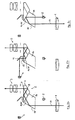
- Fig. 1a shows an afocal optical system which, in addition to a telescope with reiv1, prism system 2 and eyepiece 3 a deliberatelyaptnde display 4, and a light source 5 irradiating the observed object, e.g. a Laserdieode, as a transmitting element of a distance meter contains.
- the core element is the prism system 2, which consists of a roof prism 6 and a reflection prism 7.
- the roof edge 8 of the roof prism 6 is inclined relative to the base surface 9.
- the gable surface 10 is inclined.
- the reflection prism 7 is attached to the gable surface 10 with its reflecting surfaces 7 ', 7 "lying opposite one another at right angles to the gable surface 10.
- a beam-dividing coating 10' is applied to the gable surface 10.
- the two prisms are preferably cemented together
- Beam splitter 10 'and optical axis 11 is here 60 ° and is chosen so that the beam entrance of the observation beam path perpendicular to the glass / air surface 7' takes place on the reflection prism 7.
- the beam splitter 10 ' is used in transmission small axial offset between the beam path entering the prism system and the beam path exiting the eyepiece 3.
- Fig. 1 b shows the reflection of the display 4 in the optical path leading to the eyepiece 3.
- the imaging beams are also introduced perpendicular to the glass / air surface 9 of the roof prism 6 in the roof prism 6.
- the imaging beams are superimposed on the observation beam path. The reflection takes place at the same base surface 9 as for the exit of the observation beams to the eyepiece 3, but in one of them geometrically separate area.
- Fig. 1 c shows the coupling of the light source 5 in the lens-side beam path.
- the beam entry also takes place perpendicular to the glass / air surface 7 'on the reflection prism 7, again in a region which is geometrically separated from the entrance region of the observation beams.
- the beam splitter 10 also works here in reflection. Does it come to the Coupling efficiency of the light source, one will select high the reflection for the relevant (usually in the near infrared) wavelength, which generally leads to dichroic dividers.
- the embodiment shown in Fig. 2a to c differs from the embodiment shown in Figure 1 only in the design of the reflection prism 14, which is adjacent to the gable surface 10 in the region of the base surface 9 first reflection surface 14 'for the incoming observation beams perpendicular to the gable surface 10 stands. Although this results in a larger axial offset between the lens side and eyepiece beam paths, but for the number of deflections in the prism system is lower.
- the choice between the two embodiments will be based on the space available in the far-optical device to be set up.
- Fig. 3 shows a variant of the embodiment shown in Fig. 2, for which also the available space conditions are crucial.
- the display 4 is coupled via a made in front of the light source 5 divider mirror 15 in the laser beam path.
- the splitter mirror passes the laser wavelength, but reflects the display wavelength.
- the display wavelength is partially transmitted and directed via an additional concave mirror 16 again on the beam splitter 10 ⁇ and this time superimposed on the exiting observation beam path after partial reflection.
- a recording beam path is shown for the measuring radiation reflected by the observed object, from which a distance measuring signal is obtained and displayed on the display 4.
- the Recording beam path consists of an objective 17 and a receiving diode 18 and is aligned generally parallel to the observation beam path.
- a separate transmission beam path can also be provided.
- the light source 5 and the display 4 can be introduced without detour via the splitter mirror 15 in the prism system and further in the observation beam path.
Landscapes
- Physics & Mathematics (AREA)
- Astronomy & Astrophysics (AREA)
- General Physics & Mathematics (AREA)
- Optics & Photonics (AREA)
- Optical Elements Other Than Lenses (AREA)
- Telescopes (AREA)
- Investigating Or Analysing Materials By Optical Means (AREA)
- Instruments For Viewing The Inside Of Hollow Bodies (AREA)
- Microscoopes, Condenser (AREA)
Abstract
Description
Die Erfindung betrifft ein Prismensystem zur Bildumkehr in einem visuellen Beobachtungsstrahlengang, das aus einem Dachkantprisma mit zur Basisfläche geneigter Dachkante und einer zur Basisfläche schräg gestellten Giebelfläche besteht, an die ein Reflexionsprisma angefügt ist, wobei dieses Reflexionsprisma eine zur Basisfläche des Dachkantprismas parallele Strahlendurchtrittsfläche aufweist.The invention relates to a prism system for image reversal in a visual observation beam path, which consists of a roof prism with roof surface inclined to the base surface and an inclined to the base surface gable surface to which a reflection prism is added, said reflection prism has a parallel to the base surface of the roof prism beam passing surface.
Ein solches Prismensystem ist aus DE-PS 518 143 bekannt und wird dort als parallelsichtiges Umkehrprismensystem bezeichnet. Es weist nur zwei an Luft grenzende, zueinander parallele Strahlendurchtrittsflächen und sechs Spiegelflächen auf, die so angeordnet sind, daß sämtliche Spiegelungen in einer Ebene erfolgen und sämtlich totalreflektierend sind. Die Abbildungstrahlen treten in die Basisfläche des Dachkantprismas ein. Der Winkel zwischen der Basisfläche des Dachkantprismas und der angekitteten nächsten Reflexionsfläche soll kleiner als 110° sein. Solche Prismensysteme werden üblicherweise in afokale optische Abbildungssysteme, wie z.B. bei Fernrohren, eingesetzt.Such a prism system is known from DE-PS 518 143 and is referred to there as a parallel reversing prism system. It has only two airborne, parallel beam passing surfaces and six mirror surfaces which are arranged so that all reflections occur in one plane and are all totally reflecting. The picture rays enter the base area of the roof prism. The angle between the base surface of the roof prism and the cemented next reflection surface should be less than 110 °. Such prism systems are commonly used in afocal optical imaging systems, e.g. used in telescopes.
In den letzten Jahren sind zunehmend femoptische Instrumente, vor allem Ferngläser, auf den Markt gekommen, die Zusatzfunktionen, wie etwa Laserdistanzmessung oder Neigungs- und Richtungsmessung (Kompaß), aufweisen. Die Meßresultate werden dabei vorzugsweise so angezeigt, daß sie beim Blick in das Okular ablesbar sind. Hierbei gibt es zwei Möglichkeiten, nämlich die Anzeige der Meßresultate am Bildfeldrand außerhalb des eigentlichen Sehfeldes oder aber die Einblendung in das Bildfeld hinein, indem man sie mittels eines in den Strahlengang eingefügten Strahlteilers dem Bild überlagert. Diese Variante ist als die ergonomisch günstigere vorzuziehen, da das Einblenden am Bildfeldrand beim Ablesen zu einem Verdrehen des Auges führt, bei dem sich die Pupille des Auges aus der Austrittspupille des Fernglases zunächst herausbewegt, da der Augendrehpunkt typischerweise mehr als einen Zentimeter hinter der Pupille liegt. Durch Parallelverschieben des Fernglases muß daher die Austrittspupille jeweils neu gesucht werden.In recent years, increasingly femoptische instruments, especially binoculars, come on the market, the additional functions, such as laser distance measurement or inclination and direction measurement (compass), have. The measurement results are preferably displayed so that they can be read when looking into the eyepiece. There are two possibilities, namely the display of the measurement results at the edge of the image field outside the actual field of view or else the insertion into the image field by superimposing them on the image by means of a beam splitter inserted into the beam path. This variant is to be preferred as the ergonomically favorable, since the fade in at the edge of the field when reading to a Twisting the eye leads, in which the pupil of the eye initially moved out of the exit pupil of the binoculars, since the eye pivot is typically more than an inch behind the pupil. By parallel displacement of the binoculars, therefore, the exit pupil must each be newly searched.
Der Einsatz eines Strahlteilers zur Bildüberlagerung bietet demgegenüber die zusätzliche Möglichkeit, etwa bei Anwendung als kombiniertes Fernglas mit Laserdistanzmesser den Beobachtungsstrahlengang für das Senden oder Empfangen der Laserstrahlung mitzubenutzen. Für die Strahlteiler eignen sich neben metallischen oder dielektrischen Neutralteilern vor allem dichroitische Teiler, da die Anzeigewellenlänge eines Displays meist am roten Rand des sichtbaren Spektrums, ein möglicher Diodenlaser aber vorzugsweise im nahen Infrarot emittiert.In contrast, the use of a beam splitter for image superimposition offers the additional possibility of sharing the observation beam path for transmitting or receiving the laser radiation, for example when used as combined binoculars with a laser distance meter. In addition to metallic or dielectric neutral dividers, dichroic splitters are particularly suitable for the beam splitters since the display wavelength of a display usually emits at the red edge of the visible spectrum, but a possible diode laser preferably emits in the near infrared.
Es sind verschiedene Lösungen bekanntgeworden, wie das Einblenden in das Bildfeld mittels eines Strahlteilers vorgenommen werden kann. Aus DE 41 35 615 A1 ist es bekannt, entweder zwischen Objektiv und Umkehrsystem oder zwischen Umkehrsystem und Okular einen Strahlteiler einzufügen. Verwendet man eine einfache Planplatte mit entsprechender Spiegelschicht als Strahlteiler, so ist mit Bildfehlem (Astigmatismus) zu rechnen. Teilerwürfel mit Spiegelfläche in einer Diagonalfläche hingegen sind teuer und erhöhen den Glasweg. Außerdem führen die zumeist unter 45° zur optischen Achse angeordneten Teilerschichten zu einem Farbstichverlauf über das Bildfeld.Various solutions have become known, such as the fading can be made in the image field by means of a beam splitter. From DE 41 35 615 A1 it is known to insert a beam splitter either between the objective and the reversing system or between the reversing system and the eyepiece. If a simple plane plate with a corresponding mirror layer is used as the beam splitter, image aberration (astigmatism) is to be expected. Divider cubes with a mirror surface in a diagonal surface, however, are expensive and increase the glass path. In addition, the splitter layers, which are usually arranged at 45 ° to the optical axis, lead to a color cast course over the image field.
Eine weitere Lösung ist aus DE 37 04 848 C2 bekannt. Dabei wird die Einblendung direkt an einem aus drei Halbwürfelprismen aufgebauten Umkehrprisma vorgenommen, bei dem die Strahleneintrittsachse gegenüber der Strahlenaustrittsachse höhenversetzt ist. Zur Einblendung in den Beobachtungsstrahlengang wird auf eine unter 45° zur Strahlenrichtung stehende Reflexionsfläche des Umkehrprismas ein Strahlteilerbelag aufgebracht und danach ein Halbwürfel aufgekittet. Die Reflexionsfläche wird dabei nach wie vor für das Bild in Reflexion benutzt, während die Einblendung der Anzeige oder einer Laserstrahlung in Transmission erfolgt. Auch diese Lösung hat Nachteile. Einerseits wird die Reflexionsfläche nicht nur unter dem Winkel von 45° beansprucht, sondern aufgrund der endlichen Öffnung sowie des ausgedehnten Bildfeldes z.B. unter einem Winkel von 45 ± 5°. Dies führt insbesondere bei dichroitischen Strahlteilern zu einem Farbstichverlauf sowohl über das Bildfeld als auch über die Pupille. Außerdem nimmt die Reflexion des Strahlteilers am Rand des Winkelbereiches wegen des Brewster-Effektes speziell für höherbrechende Gläser wie BaK4, die heute für Umkehrprismen in Ferngläsern hauptsächlich eingesetzt werden, stark ab, was zu einem Helligkeitsabfall führt.Another solution is known from DE 37 04 848 C2. In this case, the insertion is made directly on a constructed from three semi-cube prisms reversing prism, in which the beam entrance axis is offset in height relative to the beam exit axis. For insertion into the observation beam path, a beam splitter coating is applied to a reflection surface of the reversing prism which is at 45 ° to the beam direction and then a half cube is cemented up. The reflection surface is still used for the image in reflection, while the display is superimposed or a laser radiation in transmission. This solution also has disadvantages. On the one hand, the reflection surface is not only stressed at an angle of 45 °, but due to the finite aperture and the extended image field, for example at an angle of 45 ± 5 °. this leads to especially with dichroic beam splitters to a color cast course over both the field of view and the pupil. In addition, the reflection of the beam splitter at the edge of the angular range due to the Brewster effect, especially for higher-refractive glasses such as BaK4, which are now used for reverse prisms in binoculars mainly decreases sharply, resulting in a decrease in brightness.
Aus WO 99/06870 A ist ein Porro-Prismensystem erster Art bekannt, an das ein weiteres Prisma zur Ausblendung eines Bildaufnahmestrahlenganges aus dem Beobachtungsstrahlengang, bzw. zur Einblendung eines Bildwiedergabestrahlenganges in den Beobachtungsstrahlengang angekittet ist. Die zur Reflexion des Beobachtungsstrahlenganges und zur Aus- oder Einblendung der weiteren Strahlengänge dienende Kittfläche ist als Strahlenteiler ausgebildet. Der Beobachtungsstrahlengang ist geradsichtig mit einem Achsenversatz.From WO 99/06870 A, a Porro prism system of the first type is known, to which a further prism for masking an image recording beam path from the observation beam path, or for glaring an image reproduction beam path is cemented into the observation beam path. The cement surface serving to reflect the observation beam path and to emit or fade in the further beam paths is designed as a beam splitter. The observation beam path is straight with an axis offset.
Aus DE 26 25 081 A ist ein Dachkantprisma bekannt, an dessen Giebelfläche ein rechtwinkliges Prisma mit seiner Hypothenusenfläche aufgekittet ist. Eine der Kathetenflächen ist parallel zur Basisfläche des Dachkantprismas ausgerichtet. Die Kittfläche ist als Strahlteiler ausgebildet. Der in das Dachkantprisma eintretende Beobachtungsstrahl wird an der Dachkante parallel zur Basisfläche reflektiert und tritt nach Reflexion an der Giebelfläche parallel und entgegengerichtet zum eintretenden Beobachtungsstrahlengang aus der Basisfläche aus. Über die zur Basisfläche parallele Fläche des aufgekitteten Prismas kann dem austretenden Beobachtungsstrahlengang ein weiterer Strahlengang überlagert werden.From DE 26 25 081 A, a roof prism is known, on whose gable surface a rectangular prism is cemented with its Hypothenusenfläche. One of the catheter surfaces is aligned parallel to the base surface of the roof prism. The cemented surface is designed as a beam splitter. The observation beam entering the roof prism is reflected parallel to the base surface at the edge of the roof and, after reflection on the gable surface, emerges parallel and opposite to the entering observation beam path from the base surface. About the surface parallel to the base surface of the cemented prism can be superimposed on the emerging observation beam path, a further beam path.
Der Erfindung lag daher die Aufgabe zugrunde, bei einem geradsichtigen Prismensystem eine Möglichkeit der Einspiegelung zusätzlicher Strahlengänge in den Beobachtungsstrahlengang zu schaffen, die die Abbildungsqualität des Beobachtungsstrahlenganges nicht beeinflußt und die sich mit geringem Bauteileaufwand realisieren läßt.The invention therefore an object of the invention to provide a possibility of reflection of additional beam paths in the observation beam path in a straight prism system, which does not affect the imaging quality of the observation beam path and can be realized with low component complexity.
Diese Aufgabe wird mit einem Prismensystem der eingangs genannten Art durch die Merkmale des unabhängigen Anspruchs 1 gelöst.This object is achieved by a prism system of the type mentioned by the features of independent claim 1.
Bei der erfindungsgemäßen Vorrichung ist der Giebelfläche (10) eine strahlenteilende Beschichtung (10') zugeordnet. Diese soll vorzugsweise für den Spektralbereich der Beobachtungsstrahlen transmittierend und für den Spektralbereich der Meßwertanzeige und der Entfernungsmessung reflektierend sein. Es ist jedoch auch möglich, als Strahlenteiler einen dielektrischen oder metallischen Neutralteiler mit einem Reflexionsanteil zwischen 10 und 40% vorzusehen. Eine Optimierung kann auch darin bestehen, den Strahlenteiler als dichroitischen Teiler mit guter Transmission im sichtbaren Spektralbereich und guter Reflexion im infraroten Spektralbereich auszubilden.In the case of the device according to the invention, the gable surface (10) is assigned a beam-dividing coating (10 '). This should preferably be reflective for the spectral range of the observation beams and reflective for the spectral range of the measured value display and the distance measurement. However, it is also possible to provide as a beam splitter a dielectric or metallic neutral divider with a reflectance of between 10 and 40%. An optimization can also be to form the beam splitter as a dichroic splitter with good transmission in the visible spectral range and good reflection in the infrared spectral range.
Die schräggestellte Giebelfläche des Dachkantprismas soll mit der Basisfläche einen Winkel von 22,5 bis 30° bilden. Als Reflexionsprisma wird vorzugsweise ein Rechteckprisma ausgewählt. In einer Ausführungsform können die einen rechten Winkel bildenden Reflexionsflächen dabei der Giebelfläche gegenüber liegen. Es ist jedoch auch möglich, eine der Reflexionsflächen unter einem Winkel von 90° auf dem zur Basisfläche des Dachkantprismas weisenden Bereich der Giebelfläche auszurichten. Als Strahleneintrittsfläche für dasThe sloping gable surface of the roof prism should form an angle of 22.5 to 30 ° with the base surface. As a reflection prism, a rectangular prism is preferably selected. In one embodiment, the reflective surfaces forming a right angle may face the gable surface. However, it is also possible to align one of the reflection surfaces at an angle of 90 ° on the pointing to the base surface of the roof prism region of the gable surface. As a radiation entrance surface for the
Beobachtungsstrahlenbündel wird zweckmäßigerweise die Strahlendurchtrittsfläche des Reflexionsprismas gewählt.Observation beam is suitably chosen the beam passing surface of the reflection prism.
Ein wesentlicher Schritt zur Lösung der der Erfindung zugrunde liegenden Aufgabe besteht in der Auswahl des nur aus zwei Glasteilen aufgebauten Umkehrsystems, was zu einer erheblichen Kosteneinsparung führt. Ein weiteres Hauptmerkmal ist, daß die Einspiegelung am Umkehrsystem beibehalten werden konnte, so daß ein separates Strahlenteilerelement entfällt. Für die Einspiegelung wird jetzt jedoch eine Fläche verwendet, die vom eigentlichen Fernrohrstrahlengang in Transmission und nicht in Reflexion beansprucht wird. Die gewählte Neigung der Giebelfläche des Dachkantprismas ergibt einen wesentlich steileren Einfallswinkel, unter dem diese Fläche vom Strahlengang durchsetzt wird, nämlich typischerweise in einem Bereich von 60 bis 67,5° (entsprechend 22,5 bis 30° zum Lot auf diese Fläche). Dies ermöglicht die Konzeption dichroitischer Strahlenteiler mit wesentlich geringerem Farbstichverlauf und gleichmäßig hoher Transmission in einem Winkelbereich von ±5°. Statt eines dichroitischen Strahlenteilers kann auch ein, z.B. metallischer Neutralteiler eingesetzt werden. Da in den meisten Anwendungen das Strahlteilerverhältnis zugunsten des Fernglas-Bildes gewählt wird, ergibt sich zwangsläufig eine wenig absorbierenden Teilerschicht, wobei gleichzeitig die verbleibende Reflexion noch für eine geeignete Einspiegelung der Meßwertanzeige und eine augensichere Auskopplung der Laserstrahlung ausreicht.An essential step in the solution of the problem underlying the invention consists in the selection of the constructed only of two glass parts reversing system, which leads to a significant cost savings. Another key feature is that the reflection on the inverting system could be maintained, eliminating the need for a separate beam splitter element. For the reflection, however, now an area is used, which is claimed by the actual telescope beam path in transmission and not in reflection. The selected inclination of the gable surface of the roof prism results in a much steeper angle of incidence at which this surface is penetrated by the beam path, namely typically in a range of 60 to 67.5 ° (corresponding to 22.5 to 30 ° to the solder on this surface). This allows the design of dichroic beam splitters with significantly lower color cast and uniformly high transmission in an angular range of ± 5 °. Instead of a dichroic beam splitter, a, e.g. metallic neutral divider can be used. Since the beam splitter ratio is chosen in favor of the binocular image in most applications, inevitably results in a little absorbing splitter layer, at the same time the remaining reflection still sufficient for a suitable reflection of the measured value display and eye-safe coupling of the laser radiation.
Ausführungsbeispiele des erfindungsgemäßen Prismensystems sind in der Zeichnung schematisch dargestellt und werden nachfolgend anhand der Figuren näher beschrieben. Dabei zeigen
- Fig.1a
- ein erstes Prismensystem mit Beobachtungsstrahlengang,
- Fig.1b
- dasselbe Prismensystem mit Strahlengang zur Anzeigeneinspiegelung,
- Fig.1c
- dasselbe Prismensystem mit Strahlengang zur Entfernungsmessung,
- Fig.2a
- ein zweites Prismensystem mit Beobachtungsstrahlengang,
- Fig.2b
- dasselbe Prismensystem mit Strahlengang zur Anzeigeneinspiegelung,
- Fig.2c
- dasselbe Prismensystem mit Strahlengang zur Entfemungsmessung,
- Fig.3
- das zweite Prismensystem mit kombinierter Anzeigeneinspiegelung und Laserstrahl-Auskopplung.
- 1a
- a first prism system with observation beam path,
- 1b shows
- the same prism system with beam path for display reflection,
- Figure 1C
- the same prism system with beam path for distance measurement,
- 2a
- a second prism system with observation beam path,
- 2b
- the same prism system with beam path for display reflection,
- Figure 2c
- the same prism system with beam path for distance measurement,
- Figure 3
- the second prism system with combined display reflection and laser beam decoupling.
Fig. 1a zeigt ein afokales optisches System, das neben einem Fernrohr mit Objektiv1, Prismensystem 2 und Okular 3 eine einzuspiegelnde Anzeige 4, sowie eine auf den beobachteten Gegenstand strahlende Lichtquelle 5, z.B. eine Laserdieode, als Sendeelement eines Distanzmessers enthält. Kernelement ist das Prismensystem 2, das aus einem Dachkantprisma 6 und einem Reflexionsprisma 7 besteht.Fig. 1a shows an afocal optical system which, in addition to a telescope with Objektiv1, prism system 2 and eyepiece 3 a
Die Dachkante 8 des Dachkantprismas 6 ist gegenüber der Basisfläche 9 geneigt. Die Giebelfläche 10 ist schräg gestellt. An die Giebelfläche 10 ist das Reflexionsprisma 7 angefügt, wobei dessen rechtwinklig aufeinander stoßende Reflexionsflächen 7', 7" der Giebelfläche 10 gegenüber liegen. Auf die Giebelfläche 10 ist eine strahlenteilende Beschichtung 10' aufgebracht. Die beiden Prismen werden vorzugsweise miteinander verkittet. Der Winkel zwischen Strahlenteiler 10' und optischer Achse 11 beträgt hier 60° und ist so gewählt, daß der Strahleneintritt des Beobachtungsstrahlenganges rechtwinklig zur Glas-/Luft-Fläche 7' am Reflexionsprisma 7 erfolgt. Der Strahlenteiler 10' wird in Transmission benutzt. Die Anordnung zeigt einen sehr geringen Achsversatz zwischen dem in das Prismensystem eintretenden Strahlengang und dem zum Okular 3 austretenden Strahlengang.The
Fig. 1 b zeigt die Einspiegelung der Anzeige 4 in den zum Okular 3 führenden Strahlengang. Über einen Umlenkspiegel 12 und eine die Anzeige in eine Zwischenbildebene abbildende Linse 13 werden die Abbildungsstrahlen ebenfalls senkrecht zur Glas-/Luft-Fläche 9 des Dachkantprismas 6 in das Dachkantprisma 6 eingeleitet. Nach Reflexion am Strahlenteiler 10' werden die Abbildungsstrahlen dem Beobachtungsstrahlengang überlagert. Die Einspiegelung erfolgt an derselben Basisfläche 9 wie für den Austritt der Beobachtungsstrahlen zum Okular 3, jedoch in einem davon geometrisch getrennten Flächenbereich.Fig. 1 b shows the reflection of the
Fig. 1 c zeigt die Einkopplung der Lichtquelle 5 in den objektivseitigen Strahlengang. Der Strahleintritt erfolgt ebenfalls senkrecht zur Glas-/Luft-Fläche 7' am Reflexionsprisma 7, und zwar wiederum in einem Bereich, der geometrisch von dem Eintrittsbereich der Beobachtungsstrahlen getrennt ist. Der Strahlenteiler 10' arbeitet auch hier in Reflexion. Kommt es auf den Einkoppelwirkungsgrad der Lichtquelle an, wird man die Reflexion für die betreffende (meist im nahen Infrarot liegende) Wellenlänge hoch wählen, was im allgemeinen zu dichroitischen Teilern führt. Dennoch ist es denkbar, auch in diesem Fall mit einem (metallischen) Neutralteiler zu arbeiten und mit einer Reflexion von beispielsweise 20 bis 30% eine ausreichende Einkoppelintensität zu finden, da moderne Laserdioden sehr leistungsfähig sind und die auszusendende Strahlungsleistung durch die Augensicherheitsvorschriften ohnehin begrenzt ist.Fig. 1 c shows the coupling of the
Das in Fig. 2a bis c gezeigte Ausführungsbeispiel unterscheidet sich von dem in Fig.1 gezeigten Ausführungsbeispiel lediglich in der Gestaltung des Reflexionsprismas 14, dessen an die Giebelfläche 10 im Bereich der Basisfläche 9 angrenzende erste Reflexionsfläche 14' für die eintretenden Beobachtungsstrahlen senkrecht auf der Giebelfläche 10 steht. Dadurch ergibt sich zwar ein größerer Achsversatz zwischen den objektivseitigen und okularseitigen Strahlengängen, aber dafür ist die Anzahl der Umlenkungen im Prismensystem geringer. Die Auswahl zwischen den beiden Ausführungsbeispielen wird sich nach den vorhandenen Platzverhältnissen in dem aufzubauenden fernoptischen Gerät richten.The embodiment shown in Fig. 2a to c differs from the embodiment shown in Figure 1 only in the design of the
Fig. 3 zeigt eine Variante zu dem in Fig. 2 dargestellten Ausführungsbeispiel, für die ebenfalls die vorhandenen Platzverhältnisse entscheidend sind. Die Anzeige 4 wird über einen vor die Lichtquelle 5 gestellten Teilerspiegel 15 in den Laserstrahlengang eingekoppelt. Der Teilerspiegel läßt die Laserwellenlänge durch, reflektiert jedoch die Anzeigewellenlänge. An dem Strahlenteiler 10' wird die Anzeigewellenlänge zum Teil durchgelassen und über einen zusätzlichen Konkavspiegel 16 erneut auf den Strahlenteiler 10` gerichtet und diesmal nach teilweiser Reflexion dem austretenden Beobachtungsstrahlengang überlagert. Indem die Transmission des Strahlenteilers 10` bei der Anzeigewellenlänge (i.a. rot) mit rund 50% und im mittleren Bereich der sichtbaren Beobachtungsstrahlen mit etwa 70 bis 80% gewählt wird, läßt sich auch hier ein brauchbarer Kompromiß für eine ausreichende Anzeigendarstellung im Bildfeld finden.Fig. 3 shows a variant of the embodiment shown in Fig. 2, for which also the available space conditions are crucial. The
Zusätzlich gezeigt ist ein Aufnahmestrahlengang für die vom beobachteten Gegenstand reflektierte Meßstrahlung, aus der ein Distanzmeßsignal gewonnen und über die Anzeige 4 zur Darstellung gebracht wird. Der Aufnahmestrahlengang besteht aus einem Objektiv 17 und einer Empfangsdiode 18 und ist im allgemeinen parallel zum Beobachtungsstrahlengang ausgerichtet.In addition, a recording beam path is shown for the measuring radiation reflected by the observed object, from which a distance measuring signal is obtained and displayed on the
Selbstverständlich kann zusätzlich zum Aufnahmestrahlengang für die Distanzmessung auch ein separater Sendestrahlengang vorgesehen sein. In diesem Fall entfällt in Fig. 3 die Lichtquelle 5 und die Anzeige 4 kann auch ohne Umweg über den Teilerspiegel 15 in das Prismensystem und weiter in den Beobachtungsstrahlengang eingeleitet werden.Of course, in addition to the recording beam path for the distance measurement, a separate transmission beam path can also be provided. In this case, omitted in Fig. 3, the
Claims (9)
- Direct-vision, image-inverting prism system (2) which comprises a roof prism (6) with a roof edge (8) inclined with respect to the bottom face (9), and a gable face (10) which is placed at an angle with respect to the bottom face (9), the inclination of the roof edge (8) being selected such that a beam entering perpendicularly through the bottom face (9) is reflected by the roof edge (8) onto the bottom face (9), and a reflecting prism (7; 14) is joined to the gable face (10), this reflecting prism (7; 14) having at least one reflecting face (7''; 14') for the beam reflected at the bottom face (9), and passing through the gable face (10), as well as a face (7') parallel to the bottom face (9) for the perpendicular passage of the beam, characterized in that- the inclination of the gable face (10) to the bottom face (9) is selected such that the first beam reflected at the bottom face (9) impinges on the gable face (10) at an angle in the range of 60° to 67.5°,- the gable face (10) is assigned a beam-splitting coating (10'),- the bottom face (9) of the roof prism (6), and the face (7'), parallel thereto, of the reflecting prism (7; 14) in each case have a second beam-pass area, separated geometrically from the beam-pass area of the first beam, for the perpendicular passage of a second and/or third beam, and- the second beam-pass areas of the bottom face (9) of the roof prism (6) and of the face (7'), parallel thereto, of the reflecting prism (7; 14) being situated opposite the gable face (10) in such a way that the first beam can be superimposed on the second and/or third beams at the gable face.
- Prism system according to Claim 1, characterized in that the beam splitter (10') is transmissive for the spectral range of the observation beams and reflective for the spectral range of the measured-value display and rangefinder measurement.
- Prism system according to Claim 1, characterized in that the beam splitter (10') is formed as a dielectric or metallic neutral-density beam splitter with a reflectance between 10 and 40%.
- Prism system according to Claim 1, characterized in that the beam splitter (10') is formed as a dichroic beam splitter with good transmission in the visible spectral range and good reflection in the infrared spectral range.
- Prism system according to Claim 1, characterized in that the angled gable face (10) of the roof prism (6) forms an angle of 22.5 to 30° with the bottom face (9).
- Prism system according to Claim 1, characterized in that the reflecting prism (7) is a right-angle prism.
- Prism system according to Claim 6, characterized in that the reflecting faces of the right-angle prism, forming a right angle with each other, are located opposite the gable face (10).
- Prism system according to Claim 6, characterized in that one of the reflecting faces of the right-angle prism is at right angles to that area of the gable face (10) which points towards the bottom face (9) of the roof prism (6).
- Prism system according to Claim 1, characterized in that the beam-pass face of the reflecting prism (7) forms the entry side of the observation beam path.
Applications Claiming Priority (2)
| Application Number | Priority Date | Filing Date | Title |
|---|---|---|---|
| DE19933172A DE19933172C1 (en) | 1999-07-15 | 1999-07-15 | Prism system for image reversal in a visual observation beam path |
| DE19933172 | 1999-07-15 |
Publications (3)
| Publication Number | Publication Date |
|---|---|
| EP1069442A2 EP1069442A2 (en) | 2001-01-17 |
| EP1069442A3 EP1069442A3 (en) | 2003-08-27 |
| EP1069442B1 true EP1069442B1 (en) | 2006-01-18 |
Family
ID=7914890
Family Applications (1)
| Application Number | Title | Priority Date | Filing Date |
|---|---|---|---|
| EP00112829A Expired - Lifetime EP1069442B1 (en) | 1999-07-15 | 2000-06-17 | Prism system for image reversal in a visual observation path |
Country Status (4)
| Country | Link |
|---|---|
| US (1) | US6292314B1 (en) |
| EP (1) | EP1069442B1 (en) |
| AT (1) | ATE316250T1 (en) |
| DE (2) | DE19933172C1 (en) |
Families Citing this family (26)
| Publication number | Priority date | Publication date | Assignee | Title |
|---|---|---|---|---|
| ES2282787T3 (en) | 2003-12-12 | 2007-10-16 | Perger, Andreas, Dr. | BINOCULAR TWINS WITH INTEGRATED LASER TELEMETER. |
| US7349073B2 (en) * | 2004-08-20 | 2008-03-25 | Laser Technology, Inc. | Efficient optical system and beam pathway design for laser-based distance measuring device |
| US7450282B2 (en) * | 2005-06-16 | 2008-11-11 | Laser Technology, Inc. | High precision optical system and beam pathway design for a laser-based distance measuring device |
| IL173361A (en) * | 2005-09-12 | 2012-03-29 | Elbit Systems Ltd | Near eye display system |
| DE102008003414A1 (en) | 2008-01-08 | 2009-07-09 | Carl Zeiss Sports Optics Gmbh | Binocular binoculars |
| AT506437B1 (en) | 2008-01-31 | 2011-08-15 | Swarovski Optik Kg | OBSERVATION DEVICE WITH DISTANCE KNIFE |
| DE102009056208A1 (en) | 2009-01-13 | 2010-07-15 | Leica Camera Ag | Parallel-sided, image-reversing prism system |
| US7999924B2 (en) * | 2009-04-16 | 2011-08-16 | Kamakura Koko Co., Ltd. | Range binoculars |
| EP2244060B1 (en) * | 2009-04-22 | 2018-01-24 | Kamakura Koki Co., Ltd | Range binoculars |
| DE102009039851A1 (en) | 2009-09-03 | 2011-05-12 | Carl Zeiss Sports Optics Gmbh | Scope |
| CN101825731A (en) * | 2010-03-18 | 2010-09-08 | 昆明腾洋光学仪器有限公司 | Erecting prism group capable of displaying optical virtual front sight and character information |
| CN101852919A (en) * | 2010-03-18 | 2010-10-06 | 昆明腾洋光学仪器有限公司 | Laser and visible light light-splitting erecting prism group |
| AT510297B1 (en) * | 2010-12-07 | 2012-03-15 | Perger Andreas Dr | PRISM |
| AT510936B1 (en) * | 2010-12-23 | 2021-02-15 | Swarovski Optik Kg | TELESCOPE WITH CONNECTABLE MODULES |
| DE102011005229B4 (en) | 2011-03-08 | 2012-11-08 | Carl Zeiss Sports Optics Gmbh | Optical observation device with at least one visual observation beam path |
| US9151603B2 (en) | 2012-09-13 | 2015-10-06 | Laser Technology, Inc. | Compact folded signal transmission and image viewing pathway design and visual display technique for laser rangefinding instruments |
| JP6345914B2 (en) * | 2013-05-17 | 2018-06-20 | 株式会社ユニバーサルエンターテインメント | Rendering device and gaming machine used for gaming machine |
| US9746589B2 (en) * | 2013-08-22 | 2017-08-29 | Sintai Optical (Shenzhen) Co., Ltd. | Range finder and prism assembly thereof |
| CN105445942B (en) * | 2014-08-19 | 2017-10-27 | 信泰光学(深圳)有限公司 | Rangefinder and its division light prism apparatus |
| CZ2015627A3 (en) | 2015-09-15 | 2017-02-15 | Meopta - Optika, S.R.O. | A binocular telescope with an integrated laser rangefinder |
| CN107219621B (en) * | 2016-03-22 | 2019-10-29 | 信泰光学(深圳)有限公司 | Can ranging binoculars and its prism module |
| US10704903B2 (en) * | 2016-03-22 | 2020-07-07 | Sintai Optical (Shenzhen) Co., Ltd. | Binocular capable of measuring distance and prism and light transmitter module thereof |
| US20180106612A1 (en) * | 2016-10-19 | 2018-04-19 | Superior Optics Company | Range finding binoculars |
| CN107329277B (en) * | 2017-08-30 | 2019-07-05 | 上海脉泽光电科技有限公司 | A kind of laser ranging divided beam system |
| CN113534313A (en) * | 2020-04-15 | 2021-10-22 | 信泰光学(深圳)有限公司 | Optical device and prism module thereof |
| US12498508B2 (en) * | 2023-01-03 | 2025-12-16 | L3Harris Technologies, Inc. | Absorbing substrate mirror |
Family Cites Families (13)
| Publication number | Priority date | Publication date | Assignee | Title |
|---|---|---|---|---|
| DE518143C (en) * | 1931-02-12 | Zeiss Carl Fa | Parallel vision erecting prism system | |
| US3424516A (en) * | 1964-05-28 | 1969-01-28 | Texas Instruments Inc | Prism system comprising joined pentaprisms |
| US3484149A (en) * | 1967-04-13 | 1969-12-16 | Leitz Ernst Gmbh | Center focusing prism binocular and reticle |
| US3541919A (en) * | 1969-03-18 | 1970-11-24 | Zeiss Stiftung | View finder for a reflex camera including a roof prism |
| DE2625081C3 (en) * | 1976-06-04 | 1979-03-22 | Eltro Gmbh, Gesellschaft Fuer Strahlungstechnik, 6900 Heidelberg | Device for the automatic harmonization of several devices |
| GB1603599A (en) * | 1978-05-31 | 1981-11-25 | Nagae S | Telescope with compass |
| SE7807159L (en) * | 1978-06-22 | 1979-12-23 | Bofors Ab | LASER INSTRUMENT |
| CH672195A5 (en) * | 1986-09-18 | 1989-10-31 | Wild Heerbrugg Ag | |
| US4886347A (en) * | 1988-02-22 | 1989-12-12 | Monroe John N | Range-finding binocular |
| JPH0420915A (en) * | 1990-05-16 | 1992-01-24 | Nikon Corp | Automatic focusing telescope |
| DE4135615A1 (en) * | 1991-10-29 | 1993-05-06 | Dr. Johannes Riegl Radartechnik & Elektrooptik Ges.M.B.H., Horn, At | Optical device for weapon sights with target marking - has beam from light source within housing of optical device inserted in light path between objective lens and eyepiece |
| JPH09230243A (en) * | 1996-02-21 | 1997-09-05 | Olympus Optical Co Ltd | Combined prism optical system |
| GB9716343D0 (en) * | 1997-08-02 | 1997-10-08 | Rotacon Plc | Novel action replay binoculars |
-
1999
- 1999-07-15 DE DE19933172A patent/DE19933172C1/en not_active Expired - Fee Related
-
2000
- 2000-06-17 DE DE50012066T patent/DE50012066D1/en not_active Expired - Lifetime
- 2000-06-17 AT AT00112829T patent/ATE316250T1/en active
- 2000-06-17 EP EP00112829A patent/EP1069442B1/en not_active Expired - Lifetime
- 2000-07-14 US US09/617,492 patent/US6292314B1/en not_active Expired - Lifetime
Also Published As
| Publication number | Publication date |
|---|---|
| DE50012066D1 (en) | 2006-04-06 |
| EP1069442A2 (en) | 2001-01-17 |
| DE19933172C1 (en) | 2001-01-11 |
| ATE316250T1 (en) | 2006-02-15 |
| US6292314B1 (en) | 2001-09-18 |
| EP1069442A3 (en) | 2003-08-27 |
Similar Documents
| Publication | Publication Date | Title |
|---|---|---|
| EP1069442B1 (en) | Prism system for image reversal in a visual observation path | |
| EP1971821B1 (en) | Coordinate measurment instrument | |
| EP1150096B1 (en) | Telescope for surveying instruments, specifically for video tachymeter | |
| DE69823808T2 (en) | PICTURE SPECTROMETER | |
| DE2746076C2 (en) | Panoramic periscope for daytime and thermal imaging | |
| EP1815278A1 (en) | Telescope and pan-focal telescope comprising plan convex or plan concave lenses and deflecting means connected thereto | |
| DE4336715C2 (en) | Stereo microscope | |
| EP2295926B9 (en) | Telescopic sight | |
| EP2376972B1 (en) | Parallel-sighted, image-reversing prism system | |
| DE2714412C3 (en) | Electro-optical retro-reflective locating device, in particular a laser rangefinder with a target coupled into a sighting branch | |
| DE19725483A1 (en) | Microscope with observation optics and auto-focus | |
| DE102008062791A1 (en) | Microscope i.e. laser scanning microscope, for e.g. measuring fluorescence resonance energy transfer between fluorophores, has beam splitter including two dichroic layers arranged at angle with respect to each other | |
| EP1744195A1 (en) | Day-night vision device | |
| DE2337044C2 (en) | Day and night vision sighting device | |
| DE69320838T2 (en) | Optical observation and near infrared tracking system for a portable missile launcher | |
| DE102009006729B4 (en) | Laser scanning microscope | |
| DE1285182B (en) | Optical image splitting system for an optical surveying device for checking the squareness or alignment and optical surveying equipment equipped with this image splitting system | |
| DE10021379A1 (en) | Optical measuring arrangement, in particular for measuring the layer thickness | |
| EP1440334B1 (en) | Method and a device for the combination of a first and second beam of rays | |
| DE3642547C2 (en) | Method for harmonizing the axis of a telescopic sight and that of a thermal camera | |
| DE3146871C2 (en) | ||
| DE10122932B4 (en) | Surveying instrument with a phase difference focus detection device | |
| CH440746A (en) | Optical system | |
| EP1920287B1 (en) | Day/night-vision device | |
| DE4345485C2 (en) | Stereo microscope, e.g. for use in surgical operations |
Legal Events
| Date | Code | Title | Description |
|---|---|---|---|
| PUAI | Public reference made under article 153(3) epc to a published international application that has entered the european phase |
Free format text: ORIGINAL CODE: 0009012 |
|
| AK | Designated contracting states |
Kind code of ref document: A2 Designated state(s): AT BE CH CY DE DK ES FI FR GB GR IE IT LI LU MC NL PT SE |
|
| AX | Request for extension of the european patent |
Free format text: AL;LT;LV;MK;RO;SI |
|
| PUAL | Search report despatched |
Free format text: ORIGINAL CODE: 0009013 |
|
| AK | Designated contracting states |
Designated state(s): AT BE CH CY DE DK ES FI FR GB GR IE IT LI LU MC NL PT SE |
|
| AX | Request for extension of the european patent |
Extension state: AL LT LV MK RO SI |
|
| RIC1 | Information provided on ipc code assigned before grant |
Ipc: 7G 02B 5/04 A Ipc: 7G 02B 23/02 B Ipc: 7G 02B 23/10 B |
|
| 17P | Request for examination filed |
Effective date: 20031029 |
|
| 17Q | First examination report despatched |
Effective date: 20040115 |
|
| AKX | Designation fees paid |
Designated state(s): AT BE CH CY DE DK ES FI FR GB GR IE IT LI LU MC NL PT SE |
|
| GRAP | Despatch of communication of intention to grant a patent |
Free format text: ORIGINAL CODE: EPIDOSNIGR1 |
|
| GRAS | Grant fee paid |
Free format text: ORIGINAL CODE: EPIDOSNIGR3 |
|
| GRAA | (expected) grant |
Free format text: ORIGINAL CODE: 0009210 |
|
| AK | Designated contracting states |
Kind code of ref document: B1 Designated state(s): AT BE CH CY DE DK ES FI FR GB GR IE IT LI LU MC NL PT SE |
|
| PG25 | Lapsed in a contracting state [announced via postgrant information from national office to epo] |
Ref country code: NL Free format text: LAPSE BECAUSE OF FAILURE TO SUBMIT A TRANSLATION OF THE DESCRIPTION OR TO PAY THE FEE WITHIN THE PRESCRIBED TIME-LIMIT Effective date: 20060118 Ref country code: IE Free format text: LAPSE BECAUSE OF FAILURE TO SUBMIT A TRANSLATION OF THE DESCRIPTION OR TO PAY THE FEE WITHIN THE PRESCRIBED TIME-LIMIT Effective date: 20060118 Ref country code: FI Free format text: LAPSE BECAUSE OF FAILURE TO SUBMIT A TRANSLATION OF THE DESCRIPTION OR TO PAY THE FEE WITHIN THE PRESCRIBED TIME-LIMIT Effective date: 20060118 |
|
| REG | Reference to a national code |
Ref country code: GB Ref legal event code: FG4D Free format text: NOT ENGLISH |
|
| REG | Reference to a national code |
Ref country code: CH Ref legal event code: EP |
|
| REG | Reference to a national code |
Ref country code: IE Ref legal event code: FG4D Free format text: LANGUAGE OF EP DOCUMENT: GERMAN |
|
| REF | Corresponds to: |
Ref document number: 50012066 Country of ref document: DE Date of ref document: 20060406 Kind code of ref document: P |
|
| PG25 | Lapsed in a contracting state [announced via postgrant information from national office to epo] |
Ref country code: SE Free format text: LAPSE BECAUSE OF FAILURE TO SUBMIT A TRANSLATION OF THE DESCRIPTION OR TO PAY THE FEE WITHIN THE PRESCRIBED TIME-LIMIT Effective date: 20060418 Ref country code: DK Free format text: LAPSE BECAUSE OF FAILURE TO SUBMIT A TRANSLATION OF THE DESCRIPTION OR TO PAY THE FEE WITHIN THE PRESCRIBED TIME-LIMIT Effective date: 20060418 |
|
| PG25 | Lapsed in a contracting state [announced via postgrant information from national office to epo] |
Ref country code: ES Free format text: LAPSE BECAUSE OF FAILURE TO SUBMIT A TRANSLATION OF THE DESCRIPTION OR TO PAY THE FEE WITHIN THE PRESCRIBED TIME-LIMIT Effective date: 20060429 |
|
| GBT | Gb: translation of ep patent filed (gb section 77(6)(a)/1977) |
Effective date: 20060424 |
|
| PG25 | Lapsed in a contracting state [announced via postgrant information from national office to epo] |
Ref country code: PT Free format text: LAPSE BECAUSE OF FAILURE TO SUBMIT A TRANSLATION OF THE DESCRIPTION OR TO PAY THE FEE WITHIN THE PRESCRIBED TIME-LIMIT Effective date: 20060619 |
|
| PG25 | Lapsed in a contracting state [announced via postgrant information from national office to epo] |
Ref country code: BE Free format text: LAPSE BECAUSE OF NON-PAYMENT OF DUE FEES Effective date: 20060630 Ref country code: MC Free format text: LAPSE BECAUSE OF NON-PAYMENT OF DUE FEES Effective date: 20060630 |
|
| NLV1 | Nl: lapsed or annulled due to failure to fulfill the requirements of art. 29p and 29m of the patents act | ||
| REG | Reference to a national code |
Ref country code: IE Ref legal event code: FD4D |
|
| ET | Fr: translation filed | ||
| PLBE | No opposition filed within time limit |
Free format text: ORIGINAL CODE: 0009261 |
|
| STAA | Information on the status of an ep patent application or granted ep patent |
Free format text: STATUS: NO OPPOSITION FILED WITHIN TIME LIMIT |
|
| 26N | No opposition filed |
Effective date: 20061019 |
|
| BERE | Be: lapsed |
Owner name: LEICA CAMERA A.G. Effective date: 20060630 Owner name: PERGER, ANDREAS Effective date: 20060630 |
|
| PG25 | Lapsed in a contracting state [announced via postgrant information from national office to epo] |
Ref country code: GR Free format text: LAPSE BECAUSE OF FAILURE TO SUBMIT A TRANSLATION OF THE DESCRIPTION OR TO PAY THE FEE WITHIN THE PRESCRIBED TIME-LIMIT Effective date: 20060419 |
|
| PG25 | Lapsed in a contracting state [announced via postgrant information from national office to epo] |
Ref country code: LU Free format text: LAPSE BECAUSE OF NON-PAYMENT OF DUE FEES Effective date: 20060617 |
|
| PG25 | Lapsed in a contracting state [announced via postgrant information from national office to epo] |
Ref country code: CY Free format text: LAPSE BECAUSE OF FAILURE TO SUBMIT A TRANSLATION OF THE DESCRIPTION OR TO PAY THE FEE WITHIN THE PRESCRIBED TIME-LIMIT Effective date: 20060118 |
|
| REG | Reference to a national code |
Ref country code: DE Ref legal event code: R082 Ref document number: 50012066 Country of ref document: DE Representative=s name: STAMER, HARALD, DIPL.-PHYS., DE |
|
| REG | Reference to a national code |
Ref country code: DE Ref legal event code: R082 Ref document number: 50012066 Country of ref document: DE Representative=s name: STAMER, HARALD, DIPL.-PHYS., DE Effective date: 20150413 Ref country code: DE Ref legal event code: R081 Ref document number: 50012066 Country of ref document: DE Owner name: LEICA CAMERA AG, DE Free format text: FORMER OWNER: LEICA CAMERA AG,ANDREAS PERGER, , AT Effective date: 20150413 Ref country code: DE Ref legal event code: R081 Ref document number: 50012066 Country of ref document: DE Owner name: PERGER, ANDREAS, DR., AT Free format text: FORMER OWNER: LEICA CAMERA AG,ANDREAS PERGER, , AT Effective date: 20150413 Ref country code: DE Ref legal event code: R081 Ref document number: 50012066 Country of ref document: DE Owner name: LEICA CAMERA AG, DE Free format text: FORMER OWNERS: LEICA CAMERA AG, 35606 SOLMS, DE; PERGER, ANDREAS, DR., WIEN, AT Effective date: 20150413 Ref country code: DE Ref legal event code: R081 Ref document number: 50012066 Country of ref document: DE Owner name: PERGER, ANDREAS, DR., AT Free format text: FORMER OWNERS: LEICA CAMERA AG, 35606 SOLMS, DE; PERGER, ANDREAS, DR., WIEN, AT Effective date: 20150413 |
|
| REG | Reference to a national code |
Ref country code: FR Ref legal event code: PLFP Year of fee payment: 16 |
|
| REG | Reference to a national code |
Ref country code: FR Ref legal event code: PLFP Year of fee payment: 17 |
|
| REG | Reference to a national code |
Ref country code: FR Ref legal event code: PLFP Year of fee payment: 18 |
|
| REG | Reference to a national code |
Ref country code: FR Ref legal event code: PLFP Year of fee payment: 19 |
|
| PGFP | Annual fee paid to national office [announced via postgrant information from national office to epo] |
Ref country code: IT Payment date: 20190624 Year of fee payment: 20 Ref country code: DE Payment date: 20190619 Year of fee payment: 20 |
|
| PGFP | Annual fee paid to national office [announced via postgrant information from national office to epo] |
Ref country code: FR Payment date: 20190619 Year of fee payment: 20 |
|
| PGFP | Annual fee paid to national office [announced via postgrant information from national office to epo] |
Ref country code: CH Payment date: 20190619 Year of fee payment: 20 |
|
| PGFP | Annual fee paid to national office [announced via postgrant information from national office to epo] |
Ref country code: AT Payment date: 20190621 Year of fee payment: 20 Ref country code: GB Payment date: 20190619 Year of fee payment: 20 |
|
| REG | Reference to a national code |
Ref country code: CH Ref legal event code: PL |
|
| REG | Reference to a national code |
Ref country code: GB Ref legal event code: PE20 Expiry date: 20200616 |
|
| REG | Reference to a national code |
Ref country code: AT Ref legal event code: MK07 Ref document number: 316250 Country of ref document: AT Kind code of ref document: T Effective date: 20200617 |
|
| PG25 | Lapsed in a contracting state [announced via postgrant information from national office to epo] |
Ref country code: GB Free format text: LAPSE BECAUSE OF EXPIRATION OF PROTECTION Effective date: 20200616 |