EP1069406B1 - Méthode pour la représentation graphique d'une rue à l'avance - Google Patents
Méthode pour la représentation graphique d'une rue à l'avance Download PDFInfo
- Publication number
- EP1069406B1 EP1069406B1 EP00115343A EP00115343A EP1069406B1 EP 1069406 B1 EP1069406 B1 EP 1069406B1 EP 00115343 A EP00115343 A EP 00115343A EP 00115343 A EP00115343 A EP 00115343A EP 1069406 B1 EP1069406 B1 EP 1069406B1
- Authority
- EP
- European Patent Office
- Prior art keywords
- road
- diagrams
- driver
- marks
- vehicle
- Prior art date
- Legal status (The legal status is an assumption and is not a legal conclusion. Google has not performed a legal analysis and makes no representation as to the accuracy of the status listed.)
- Expired - Lifetime
Links
- 238000000034 method Methods 0.000 title claims description 13
- 238000010586 diagram Methods 0.000 claims description 39
- 230000001944 accentuation Effects 0.000 claims 1
- 230000001419 dependent effect Effects 0.000 claims 1
- 238000012800 visualization Methods 0.000 description 11
- 238000001514 detection method Methods 0.000 description 2
- 230000006641 stabilisation Effects 0.000 description 2
- 238000011105 stabilization Methods 0.000 description 2
- 241001609370 Puschkinia scilloides Species 0.000 description 1
- 230000004308 accommodation Effects 0.000 description 1
- 230000004438 eyesight Effects 0.000 description 1
- 230000004807 localization Effects 0.000 description 1
Images
Classifications
-
- G—PHYSICS
- G01—MEASURING; TESTING
- G01C—MEASURING DISTANCES, LEVELS OR BEARINGS; SURVEYING; NAVIGATION; GYROSCOPIC INSTRUMENTS; PHOTOGRAMMETRY OR VIDEOGRAMMETRY
- G01C21/00—Navigation; Navigational instruments not provided for in groups G01C1/00 - G01C19/00
- G01C21/26—Navigation; Navigational instruments not provided for in groups G01C1/00 - G01C19/00 specially adapted for navigation in a road network
- G01C21/34—Route searching; Route guidance
- G01C21/36—Input/output arrangements for on-board computers
Definitions
- the invention relates to a method for the graphical representation of particular properties of a road ahead in a vehicle, in particular with respect to a near area.
- the driver can grasp these details with a quick glance at the driver's screen and will not be distracted in driving situations in which he must, on the one hand, pay close attention to the real driving scene and, on the other hand, rely on such information.
- the road presentation is possible in different variants.
- the course of the road is shown in perspective (also called Aerial View, Bird View).
- the representation is made planimetrically (also called Map View), comparable to a route diagram.
- the perspective view facilitates the detection of curvatures in the course of the road due to the shortened perspective, however, more distant details are disadvantageously reduced.
- DE 195 31822 describes a representation of the best way to track a route suitable lane or road side.
- the invention has for its object to provide a method of the type mentioned in the important details clarified and displayed in sufficient size so that they can be reliably detected with a short Mahzuengine.
- the details of the road or the driving compartment or information derived from such a detail are presented in the form of controllable diagrams, which depend on the positions and / or the directions of action of the details on the road or in the driving space in certain fixed positions in the display device or be moved in certain directions in the display device.
- details of the road and the lane having importance for the vehicle guidance are displayed with a display device so as to have a sufficient size for recognition with a short gaze, and that they are not obscured or obscured.
- the representation in certain fixed positions allows the driver to localize the details on the road and in the driving area, an assessment of their characteristics and a detection of the direction of action.
- the diagrams are thereby controlled by data provided by modules of a device for graphical representation of a road area, as described, for example, in the abovementioned publication, preferably the navigation computer, the vehicle sensor system, the vehicle communication system, the special databases and the web analyzer.
- the display positions of the details are assigned to the corresponding positions in the car or on the road, respectively, such that information originating from a detail which is at a certain distance ahead or acts in that direction is displayed at an upper level with the display device Area is displayed, and that information that arises close to the vehicle is displayed with the display device in a lower area, and that the information from right or left or right or left-acting details according to right or left lying or is shown in the form of a movement to the right or left with the display device.
- This method of representation ensures that the underlying details are localized by the driver, in that the attributes far, near, right, and left are meaningfully assigned to the representation at the top, bottom, right, left.
- the diagrams are preferably designed as bar graphs, wherein the bars are changed in length and / or brightness and / or color and / or with other graphical means of expression.
- a large length or a high brightness or a signal color corresponds to a strong characteristic or a great significance for the vehicle guidance.
- a further preferred embodiment consists of movable marks and structures, which in particular represent right- or left-lying or acting to the right or left details.
- the diagrams are preferably straight.
- a curved execution may be advantageous in representing certain details.
- the diagram may also include one or more marks in certain fixed positions whose position, brightness, color, fill pattern contains additional information about details of the road and / or the driving range.
- the diagrams and marks on the driver's screen are located in certain fields forming a frame, the frame preferably enclosing the road visualization.
- diagrams and marks are according to their assignment to a certain lying ahead or close to the vehicle, or right or left area as separate displays above or below or right or left in the central area of the Instrument panel in front of the driver, not necessarily a road visualization is provided.
- the diagrams and marks are in one or more display devices that are particularly suitable for displaying bar graphs and that are not necessarily associated with a driver's screen.
- the display device is preferably arranged in the instrument panel in front of the driver and / or in the upper area of the instrument panel on the right and / or left, because these areas are particularly suitable for observation by the driver.
- the display device is located in a collimated beam path in the instrument panel in front of the driver and / or in the upper area of the instrument panel on the right and / or left.
- a collimated beam path in the case of a collimated beam path, the representation appears to take place at a greater distance, so that advantageously the accommodation is not changed.
- information about geometric characteristics of the preceding road course preferably the strength of the curvature and the direction of curvature of preceding curves and turns, on other road users and obstacles in the car on the own and adjacent lanes, on the side position of the own vehicle, based on the totality of adjacent lanes and on the vehicle direction, based on the local direction of the lanes, shown.
- the information about other details can be displayed in the same way, but a limitation to the representation of the most important for the vehicle guidance information is preferable.
- the advantage of the inventive representation of details of the road and the driving space is that the presentation is not bound to the visualization of the road, but rather in the choice of the presentation, the size of the presentation and the representation of the direction of action is free.
- a non-linear representation for example, to highlight only weak details.
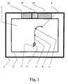
- FIG. 1 the diagrams are shown in a frame of the image field of the road visualization 1 known per se.
- the entire image field is characterized by the border line 2, and the image field of the street visualization 1 by the border line 3. This also applies to FIGS. 2 and 3.
- the image field of the road visualization 1 contains the technical state of the representation of a piece of road 4, which is the vehicle ahead, represented by a symbol 5, ahead. It is also a distance mark 6, which is in a selectable constant distance, for example, 200m, in front of the vehicle 5 is shown.
- the marks 7, 8, 9 delimit, for example, two distances on the road piece 4, wherein the first distance lies for the most part in front of the vehicle 5, the second distance in equal parts in front of and behind the distance mark 6.
- the mean value of the curvature and the mean curvature direction are calculated for the first and the second distance and shown in a respective diagram bar 11, 12.
- the areas of the diagram bars 11, 12 have different color, structure, brightness for unambiguous assignment to the area around the vehicle 5 and to the area around the distance mark 6.
- the associated diagram bar 11 is thus represented with a dominant color, structure, brightness and covers the diagram bar 12 if both diagram bars lie on the same side.
- the diagram bar 12 serves to inform the driver in advance about the next expected curve curvature.
- the beam length is non-linearly calculated from the mean curvature of the assigned area in such a way that small curvatures, which would not be clearly visible in the field of the road visualization 1, for example immediately in front of the vehicle, are highlighted in the bar graphs 11, 12 ,
- a middle separator field 10 supports the recognition of the bar directions “right” and "left”.
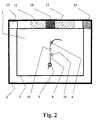
- Fig. 2 are vehicles or obstacles in the driving compartment on the road ahead, and the own vehicle is equipped in a conventional manner with a sensor device for detecting such obstacles.
- a preceding vehicle 15 on the own roadway 4 and a stationary vehicle 16 on the right adjacent roadway are shown schematically.
- the fields of these marks are empty if there are no vehicles or obstacles in the area lying ahead, for example in the area bounded by the distance mark 6.
- the mark 13 is empty.
- the marks 10, 13, 14 have constant size. You get a color, structure, brightness depending on the meaning the vehicle or obstacle 15, 16 displayed therein for own vehicle guidance.
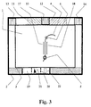
- Fig. 3 shows in a conventional manner in the inner panel of the street visualization 1 three adjacent lanes 4, 17 and 18, wherein the vehicle 5 is located on the middle lane 4.
- the instantaneous lateral position of the vehicle 5 and the instantaneous direction of the vehicle longitudinal axis or the travel relative to the local road direction 22 are shown in a diagram 19.
- the diagram also contains a vehicle symbol 21, with which a directional representation is made.
- the cross section of the entirety of the adjacent lanes and guidelines 20 are shown.
- the diagram 19 may include a road-facing center mark 22 in the center of the lower frame field.
- the center of the lane best suited for tracking the route is centered on the center 22 of the lower frame field so that the driver can recognize the lateral deviation from the appropriate lane and guide the vehicle accordingly.
- the reason may be that the driver can not recognize the real road markings due to, for example, snow cover.
- the diagram 19 gives him the information necessary to correct his lane and direction choice.
- the instantaneous direction of the vehicle's longitudinal axis or travel relative to the local road 22 direction is calculated and displayed non-linearly, so that slight deviations of the direction of the vehicle longitudinal axis or the drive from the local road direction in the representation 21 are highlighted.
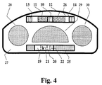
- Fig. 4 shows the representation of diagrams according to the invention in the area of the instrument panel 27.
- the diagram 25 according to its information about a situation close to the vehicle below, the diagram 26 arranged according to the representation of a certain distance situation above.
- the instrument panel 27 contains in a conventional manner further display elements, here for example the instruments 28, 29 and 30, of which the central instrument 29, the diagrams according to the invention 25 and 26 optically separates.
- the instruments 28, 29 and 30 of which the central instrument 29, the diagrams according to the invention 25 and 26 optically separates.
- the central instrument 29 the diagrams according to the invention 25 and 26 optically separates.
- only characteristics of the road (in diagram 26) and the vehicle position on the road (in diagram 25) are represented, but not the road itself.
Landscapes
- Engineering & Computer Science (AREA)
- Radar, Positioning & Navigation (AREA)
- Remote Sensing (AREA)
- Automation & Control Theory (AREA)
- Physics & Mathematics (AREA)
- General Physics & Mathematics (AREA)
- Instrument Panels (AREA)
- Traffic Control Systems (AREA)
- Navigation (AREA)
Claims (8)
- Procédé de représentation graphique de particularités d'une rue ou l'avant au moyen d'un dispositif d'affichage dans un véhicule,
caractérisé en ce que
la représentation de détails de la rue ou de l'espace de roulement ou de l'information déduite d'un tel détail est réalisée sous forme de diagrammes pouvant être commandés dont les positions dans le dispositif d'affichage sont fonction des positions et/ou des directions d'action des détails sur la rue ou dans l'espace de roulement, le centre de la voie de circulation la mieux appropriée pour suivre un trajet étant représenté de façon centrée sur le centre d'un champ de cadre inférieur. - Procédé selon la revendication 1,
caractérisé en ce que
les diagrammes sont représentés sous forme de diagrammes à barres avec des moyens d'expression graphiques tels qu'une longueur, une couleur, une luminosité et des symboles de remplissage et d'entourage variables de chacune des barres. - Procédé selon la revendication 1,
caractérisé en ce que
les diagrammes présentent la forme de marques mobiles ou de symboles graphiques mobiles. - Procédé selon la revendication 1,
caractérisé en ce que
les diagrammes contiennent une ou plusieurs marques dans des positions fixes déterminées, et la luminosité et/ou la couleur et/ou le symbole de remplissage représente une information concernant le détail. - Procédé selon la revendication 1 à 4,
caractérisé en ce que
les diagrammes et marques se situent sur un dispositif d'affichage sous forme d'écran de conducteur dans des champs déterminés qui forment un cadre autour d'un champ d'image intérieur. - Procédé selon les revendications 1 à 4,
caractérisé en ce que
les diagrammes et marques se situent dans des dispositifs d'affichage séparés qui ne sont pas nécessairement reliés à un écran de conducteur et sont de préférence disposés dans le tableau de bord devant le conducteur. - Procédé selon les revendications 1 à 4,
caractérisé en ce que
le dispositif d'affichage se situe dans une trajectoire de faisceau collimaté dans le tableau de bord ou à droite et/ou à gauche au-dessus du tableau de bord. - Procédé selon les revendications 1 à 7,
caractérisé en ce que
les diagrammes et les marques représentent en particulier l'ampleur de la courbure et la direction de la courbure de virages et de tournants situés en avant et/ou la présence d'autres usagers de la rue et d'obstacles dans l'espace de roulement sur la voie utilisée et des voies de circulation voisines et/ou la position latérale du véhicule par rapport à la rue et/ou la direction du véhicule par rapport à la direction locale de la rue.
Applications Claiming Priority (2)
| Application Number | Priority Date | Filing Date | Title |
|---|---|---|---|
| DE1999133504 DE19933504A1 (de) | 1999-07-16 | 1999-07-16 | Verfahren zur grafischen Darstellung einer vorausliegenden Straße |
| DE19933504 | 1999-07-16 |
Publications (3)
| Publication Number | Publication Date |
|---|---|
| EP1069406A2 EP1069406A2 (fr) | 2001-01-17 |
| EP1069406A3 EP1069406A3 (fr) | 2004-01-14 |
| EP1069406B1 true EP1069406B1 (fr) | 2006-11-15 |
Family
ID=7915090
Family Applications (1)
| Application Number | Title | Priority Date | Filing Date |
|---|---|---|---|
| EP00115343A Expired - Lifetime EP1069406B1 (fr) | 1999-07-16 | 2000-07-14 | Méthode pour la représentation graphique d'une rue à l'avance |
Country Status (2)
| Country | Link |
|---|---|
| EP (1) | EP1069406B1 (fr) |
| DE (2) | DE19933504A1 (fr) |
Families Citing this family (5)
| Publication number | Priority date | Publication date | Assignee | Title |
|---|---|---|---|---|
| DE19944067A1 (de) * | 1999-09-14 | 2001-03-15 | Mannesmann Vdo Ag | Verfahren zur Anzeige von Primär- und Sekundärinformationen |
| DE10131478B4 (de) * | 2001-06-29 | 2017-02-16 | Robert Bosch Gmbh | Anzeigevorrichtung für fortbewegungsmittelbezogenes Assistenz-/Unterstützungssystem |
| DE102004055258B4 (de) * | 2004-11-16 | 2006-09-07 | Daimlerchrysler Ag | Verfahren und Vorrichtung zur Darstellung von Navigationsangaben in einem Fahrzeug |
| DE102006039376A1 (de) * | 2006-08-22 | 2008-03-06 | Bayerische Motoren Werke Ag | Fahrzeug |
| DE102015201894A1 (de) * | 2015-02-04 | 2016-08-18 | Volkswagen Aktiengesellschaft | Verfahren zum Unterstützen eines Fahrers eines Fahrzeugs beim Einhalten einer Soll-Linie auf einer Fahrbahn |
Citations (2)
| Publication number | Priority date | Publication date | Assignee | Title |
|---|---|---|---|---|
| DE19531822A1 (de) * | 1994-10-07 | 1996-04-11 | Mannesmann Ag | Verfahren und Anzeigevorrichtung zur Zielführung eines Fahrzeugs |
| JPH09178505A (ja) * | 1995-12-27 | 1997-07-11 | Pioneer Electron Corp | 運転支援装置 |
Family Cites Families (8)
| Publication number | Priority date | Publication date | Assignee | Title |
|---|---|---|---|---|
| US3152317A (en) * | 1962-08-31 | 1964-10-06 | Tung Sol Electric Inc | Vehicle sensing means |
| JPS5618774A (en) * | 1979-07-24 | 1981-02-21 | Honda Motor Co Ltd | Radar apparatus for automobile |
| US4694295A (en) * | 1986-05-15 | 1987-09-15 | Miller Brett A | Vehicle blind spot detector |
| JPH08263784A (ja) * | 1995-03-23 | 1996-10-11 | Honda Motor Co Ltd | 道路状況認識装置 |
| US5874905A (en) * | 1995-08-25 | 1999-02-23 | Aisin Aw Co., Ltd. | Navigation system for vehicles |
| DE19531766A1 (de) * | 1995-08-29 | 1997-03-06 | Hochschorner K W Gmbh | Verfahren und Vorrichtung zur Routen- und Positionsanzeige |
| DE19648906A1 (de) * | 1996-11-26 | 1998-05-28 | Mannesmann Vdo Ag | Verfahren und Einrichtung zur Zielführungsunterstützung eines Fahrzeugführers |
| JPH10269495A (ja) * | 1997-03-26 | 1998-10-09 | Mitsubishi Motors Corp | 車両の走行補助装置 |
-
1999
- 1999-07-16 DE DE1999133504 patent/DE19933504A1/de not_active Ceased
-
2000
- 2000-07-14 EP EP00115343A patent/EP1069406B1/fr not_active Expired - Lifetime
- 2000-07-14 DE DE50013737T patent/DE50013737D1/de not_active Expired - Lifetime
Patent Citations (2)
| Publication number | Priority date | Publication date | Assignee | Title |
|---|---|---|---|---|
| DE19531822A1 (de) * | 1994-10-07 | 1996-04-11 | Mannesmann Ag | Verfahren und Anzeigevorrichtung zur Zielführung eines Fahrzeugs |
| JPH09178505A (ja) * | 1995-12-27 | 1997-07-11 | Pioneer Electron Corp | 運転支援装置 |
Also Published As
| Publication number | Publication date |
|---|---|
| EP1069406A2 (fr) | 2001-01-17 |
| DE19933504A1 (de) | 2001-01-25 |
| DE50013737D1 (de) | 2006-12-28 |
| EP1069406A3 (fr) | 2004-01-14 |
Similar Documents
| Publication | Publication Date | Title |
|---|---|---|
| DE69217311T2 (de) | Gerät und Verfahren für Kartenanzeige in der Fahrzeugnavigation | |
| EP2002212B1 (fr) | Procédé et système pour afficher des indications de navigation | |
| DE102005046672A1 (de) | Nachtsichteinrichtung | |
| DE10023530A1 (de) | Zielführungsanzeige für Navigationssysteme | |
| DE102008000606A1 (de) | Fahrzeuganzeigeinstrumentsystem und Verfahren, dieses zu steuern | |
| DE10141695A1 (de) | Verfahren zur Rückführung eines navigierbaren Objektes sowie Einrichtung hierzu | |
| DE4412859C1 (de) | Zielführungsanzeige | |
| EP3649434B1 (fr) | Procédé et dispositif pour afficher des informations concernant des voies de circulation dans un véhicule | |
| DE19738764A1 (de) | Vorrichtung zur graphischen Darstellung einer vorausliegenden Straße | |
| EP2910445B1 (fr) | Procédé d'assistance d'un conducteur pour passer dans une voie de circulation rétrécie et système d'assistance du conducteur | |
| EP0793074A1 (fr) | Méthode et dispositif pour la représentation d'une carte géographique | |
| DE19537255A1 (de) | Navigationsgerät | |
| EP1069406B1 (fr) | Méthode pour la représentation graphique d'une rue à l'avance | |
| WO2012123007A1 (fr) | Procédé servant à fournir un affichage et dispositif de navigation | |
| EP1309836B1 (fr) | Procede de representation d'un itineraire | |
| DE10157518B4 (de) | Verfahren zur Zielführung eines Fahrzeugs | |
| DE102013211134A1 (de) | Verfahren und Navigationssystem zum Darstellen von einer Fahrroute auf einer Anzeigeeinrichtung | |
| EP0941451B1 (fr) | Procede et dispositif pour l'assistance a la navigation d'un conducteur de vehicule | |
| EP1255092B1 (fr) | Dispositif et procédé pour afficher de l'information dans un véhicule | |
| EP1098171B1 (fr) | Système de navigation | |
| DE102007034931A1 (de) | Verfahren zum Betrieb eines Navigationssystems | |
| DE102004055258B4 (de) | Verfahren und Vorrichtung zur Darstellung von Navigationsangaben in einem Fahrzeug | |
| DE102019000435A1 (de) | Verfahren zur Visualisierung von Kameradaten | |
| DE102008057372A1 (de) | Verfahren zur Anzeige von Informationen einer aktiven Zielführung in einem Fahrzeug | |
| EP0829838A1 (fr) | Procédé d'affichage d'une information de direction dans un véhicule et utilisation d'un dispositif d'affichage à cet effet |
Legal Events
| Date | Code | Title | Description |
|---|---|---|---|
| PUAI | Public reference made under article 153(3) epc to a published international application that has entered the european phase |
Free format text: ORIGINAL CODE: 0009012 |
|
| AK | Designated contracting states |
Kind code of ref document: A2 Designated state(s): AT BE CH CY DE DK ES FI FR GB GR IE IT LI LU MC NL PT SE |
|
| AX | Request for extension of the european patent |
Free format text: AL;LT;LV;MK;RO;SI |
|
| PUAL | Search report despatched |
Free format text: ORIGINAL CODE: 0009013 |
|
| AK | Designated contracting states |
Kind code of ref document: A3 Designated state(s): AT BE CH CY DE DK ES FI FR GB GR IE IT LI LU MC NL PT SE |
|
| AX | Request for extension of the european patent |
Extension state: AL LT LV MK RO SI |
|
| RIC1 | Information provided on ipc code assigned before grant |
Ipc: 7G 08G 1/0962 B Ipc: 7G 01C 21/36 A Ipc: 7G 08G 1/133 B |
|
| 17P | Request for examination filed |
Effective date: 20040129 |
|
| AKX | Designation fees paid |
Designated state(s): DE FR GB IT |
|
| GRAP | Despatch of communication of intention to grant a patent |
Free format text: ORIGINAL CODE: EPIDOSNIGR1 |
|
| GRAS | Grant fee paid |
Free format text: ORIGINAL CODE: EPIDOSNIGR3 |
|
| GRAA | (expected) grant |
Free format text: ORIGINAL CODE: 0009210 |
|
| AK | Designated contracting states |
Kind code of ref document: B1 Designated state(s): DE FR GB IT |
|
| REG | Reference to a national code |
Ref country code: GB Ref legal event code: FG4D Free format text: NOT ENGLISH |
|
| REF | Corresponds to: |
Ref document number: 50013737 Country of ref document: DE Date of ref document: 20061228 Kind code of ref document: P |
|
| GBT | Gb: translation of ep patent filed (gb section 77(6)(a)/1977) |
Effective date: 20061214 |
|
| ET | Fr: translation filed | ||
| PLBE | No opposition filed within time limit |
Free format text: ORIGINAL CODE: 0009261 |
|
| STAA | Information on the status of an ep patent application or granted ep patent |
Free format text: STATUS: NO OPPOSITION FILED WITHIN TIME LIMIT |
|
| 26N | No opposition filed |
Effective date: 20070817 |
|
| REG | Reference to a national code |
Ref country code: FR Ref legal event code: PLFP Year of fee payment: 17 |
|
| REG | Reference to a national code |
Ref country code: FR Ref legal event code: PLFP Year of fee payment: 18 |
|
| REG | Reference to a national code |
Ref country code: FR Ref legal event code: PLFP Year of fee payment: 19 |
|
| PGFP | Annual fee paid to national office [announced via postgrant information from national office to epo] |
Ref country code: IT Payment date: 20190723 Year of fee payment: 20 Ref country code: FR Payment date: 20190724 Year of fee payment: 20 Ref country code: DE Payment date: 20190717 Year of fee payment: 20 |
|
| PGFP | Annual fee paid to national office [announced via postgrant information from national office to epo] |
Ref country code: GB Payment date: 20190725 Year of fee payment: 20 |
|
| REG | Reference to a national code |
Ref country code: DE Ref legal event code: R071 Ref document number: 50013737 Country of ref document: DE |
|
| REG | Reference to a national code |
Ref country code: GB Ref legal event code: PE20 Expiry date: 20200713 |
|
| PG25 | Lapsed in a contracting state [announced via postgrant information from national office to epo] |
Ref country code: GB Free format text: LAPSE BECAUSE OF EXPIRATION OF PROTECTION Effective date: 20200713 |
|
| P01 | Opt-out of the competence of the unified patent court (upc) registered |
Effective date: 20230502 |